Page 372 of 3342
 Loosen exhaust camshaft cap bolts equally, a little at a
time in the numerical sequence shown in figure.
7) Remove camshaft caps and exhaust camshaft.
CAUTION:
Arrange camshaft caps in orde")
G2M0745
6) Loosen exhaust camshaft cap bolts equally, a little at a
time in the numerical sequence shown in figure.
7) Remove camshaft caps and exhaust camshaft.
CAUTION:
Arrange camshaft caps in order so that they can be
installed in their original positions.
8) Similarly, remove right-hand camshafts and related
parts.
G2M0746
B: INSPECTION
1. CAMSHAFT
1) Measure the bend, and repair or replace if necessary.
Limit:
0.020 mm (0.0008 in)
2) Check journal for damage and wear. Replace if faulty.
3) Measure outside diameter of camshaft journal. If the
journal diameter is not as specified, check the oil clear-
ance.
Camshaft journal
Front Center, rear
Standard31.946—31.963 mm
(1.2577—1.2584 in)27.946—27.963 mm
(1.1002—1.1009 in)
B2M1216
4) Measurement of the camshaft journal oil clearance
(1) Clean the bearing caps and camshaft journals.
(2) Place the camshafts on the cylinder head. (Without
installing valve rocker.)
(3) Place plastigauge across each of the camshaft
journals.
(4) Install the bearing caps.
CAUTION:
Do not turn the camshaft.
(5) Remove the bearing caps.
(6) Measure the widest point of the plastigauge on
each journal.
If the oil clearance exceeds the limit, replace the cam-
shaft. If necessary, replace the camshaft caps and cyl-
inder head as a set.
Standard oil clearance:
0.037—0.072 mm (0.0015—0.0028 in)
Limit:
0.10 mm (0.0039 in)
(7) Completely remove the plastigauge.
31
2-3bSERVICE PROCEDURE
3. Camshaft
Page 373 of 3342
B2M1209A
5) Check cam face condition; remove minor faults by
grinding with oil stone. Measure the cam height H; replace
if the limit has been exceeded.
Cam height: H
Standard:
Intake:
42.20—42.30 mm (1.6614—1.6654 in)
Exhaust:
Front: 42.50—42.60 mm (1.6732—1.6772 in)
Rear: 41.40—41.50 mm (1.6299—1.6339 in)
Limit:
Intake:
42.04 mm (1.6551 in)
Exhaust:
Front: 42.34 mm (1.6669 in)
Rear: 41.24 mm (1.6236 in)
Cam base circle diameter A:
28.0 mm (1.102 in)
B2M1217
6) Measure the thrust clearance of camshaft with dial
gauge. If the clearance exceeds the limit, replace caps and
cylinder head as a set. If necessary replace camshaft.
Standard:
0.040—0.080 mm (0.0016—0.0031 in)
Limit:
0.1 mm (0.004 in)
32
2-3bSERVICE PROCEDURE
3. Camshaft
Page 377 of 3342
4. Cylinder Head
A: REMOVAL
1. INTAKE MANIFOLD
1) Remove V-belt.
2) Remove generator, air conditioner compressor and
brackets.
3) Remove hoses and tubes from cylinder block.
4) Disconnect each connector and/or remove connector
bracket.
5) Remove coolant filler tank.
6) Remove intake manifold assembly and gasket.
7) Remove water pipe.
8) Remove crank angle sensor, cam angle sensor and
knock sensor.
9) Remove timing belt, camshaft sprockets and related
parts.
10) Remove rocker cover, camshafts and related parts.
2. CYLINDER HEAD
B2M0770A
36
2-3bSERVICE PROCEDURE
4. Cylinder Head
Page 378 of 3342
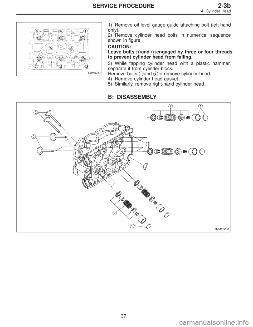
G2M0757
1) Remove oil level gauge guide attaching bolt (left-hand
only).
2) Remove cylinder head bolts in numerical sequence
shown in figure.
CAUTION:
Leave bolts�
1and�4engaged by three or four threads
to prevent cylinder head from falling.
3) While tapping cylinder head with a plastic hammer,
separate it from cylinder block.
Remove bolts�
1and�4to remove cylinder head.
4) Remove cylinder head gasket.
5) Similarly, remove right-hand cylinder head.
B: DISASSEMBLY
B2M1220A
37
2-3bSERVICE PROCEDURE
4. Cylinder Head
Page 379 of 3342
 Remove shims and valve lifters.
2) Compress the valve spring and remove the valve spring
retainer key. Remove each valve and valve spring.
ST1 498267600 CYLINDER HEAD TABLE
ST2 499718000 V")
B2M1221A
1) Remove shims and valve lifters.
2) Compress the valve spring and remove the valve spring
retainer key. Remove each valve and valve spring.
ST1 498267600 CYLINDER HEAD TABLE
ST2 499718000 VALVE SPRING REMOVER
CAUTION:
�Keep removed parts in order for re-installing in their
original positions.
�Mark each valve to prevent confusion.
�Use extreme care not to damage the lips of the
intake valve oil seals and exhaust valve oil seals.
G2M0760
C: INSPECTION
1. CYLINDER HEAD
1) Make sure that no crack or other damage exists. In
addition to visual inspection, inspect important areas by
means of red check.
2) Measure the warping of the cylinder head surface that
mates with crankcase by using a straight edge and thick-
ness gauge.
If the warping exceeds 0.05 mm (0.0020 in), regrind the
surface with a surface grinder.
Warping limit:
0.05 mm (0.0020 in)
Grinding limit:
0.3 mm (0.012 in)
Standard height of cylinder head:
127.5 mm (5.02 in)
CAUTION:
Uneven torque for the cylinder head nuts can cause
warping. When reassembling, pay special attention to
the torque so as to tighten evenly.
38
2-3bSERVICE PROCEDURE
4. Cylinder Head
Page 381 of 3342
 If the clearance between valve guide and stem exceeds
the specification, replace guide as follows:
(1) Place cylinder head on ST1 with the combustion
chamber upward so that valve guides ent")
G2M0762
2) If the clearance between valve guide and stem exceeds
the specification, replace guide as follows:
(1) Place cylinder head on ST1 with the combustion
chamber upward so that valve guides enter the holes
in ST1.
(2) Insert ST2 into valve guide and press it down to
remove valve guide.
ST1 498267600 CYLINDER HEAD TABLE
ST2 499767200 VALVE GUIDE REMOVER
G2M0763
(3) Turn cylinder head upside down and place ST as
shown in the figure.
ST 498267700 VALVE GUIDE ADJUSTER
G2M0764
(4) Before installing new valve guide, make sure that
neither scratches nor damages exist on the inside sur-
face of the valve guide holes in cylinder head.
(5) Put new valve guide, coated with sufficient oil, in
cylinder, and insert ST1 into valve guide. Press in until
the valve guide upper end is flush with the upper sur-
face of ST2.
ST1 499767200 VALVE GUIDE REMOVER
ST2 498267700 VALVE GUIDE ADJUSTER
(6) Check the valve guide protrusion.
Valve guide protrusion: L
12.0—12.4 mm (0.472—0.488 in)
(7) Ream the inside of valve guide with ST. Gently
rotate the reamer clockwise while pressing it lightly into
valve guide, and return it also rotating clockwise. After
reaming, clean valve guide to remove chips.
ST 499767400 VALVE GUIDE REAMER
CAUTION:
�Apply engine oil to the reamer when reaming.
�If the inner surface of the valve guide is torn, the
edge of the reamer should be slightly ground with an
oil stone.
�If the inner surface of the valve guide becomes lus-
trous and the reamer does not chips, use a new reamer
or remedy the reamer.
(8) Recheck the contact condition between valve and
valve seat after replacing valve guide.
40
2-3bSERVICE PROCEDURE
4. Cylinder Head
Page 385 of 3342
D: ASSEMBLY
B2M1220B
B2M1221A
1) Installation of valve spring and valve
(1) Coat stem of each valve with engine oil and insert
valve into valve guide.
CAUTION:
When inserting valve into valve guide, use special care
not to damage the oil seal lip.
(2) Set cylinder head on ST1.
(3) Install valve spring and retainer using ST2.
ST1 498267600 CYLINDER HEAD TABLE
ST2 499718000 VALVE SPRING REMOVER
CAUTION:
Be sure to install the valve springs with their painted
facing towards the valve spring retainer.
(4) Compress valve spring and fit valve spring retainer
key.
(5) After installing, tap valve spring retainers lightly
with wooden hammer for better seating.
2) Install valve lifter and shim.
44
2-3bSERVICE PROCEDURE
4. Cylinder Head
Page 389 of 3342
G2M0774
4) Install intake manifold.
CAUTION:
Use new gaskets.
5) Install coolant filler tank.
6) Install crankshaft position sensor, camshaft position
sensor and knock sensor. Use dry compressed air to
remove foreign particles before installing sensors.
7) Connect each connector and/or install connector
bracket.
8) Connect hoses and tubes to cylinder block.
9) Install brackets, generator and air conditioner compres-
sor.
10) Install V-belt.
48
2-3bSERVICE PROCEDURE
4. Cylinder Head
 Check cam face condition; remove minor faults by
grinding with oil stone. Measure the cam height H; replace
if the limit has been exceeded.
Cam height: H
Standard:
Intake:
42.20—42.30 mm")
 Remove V-belt.
2) Remove generator, air conditioner compressor and
brackets.
3) Remove hoses and tubes from cylinder block.
4) Disconnect each connect")
 Installation of valve spring and valve
(1) Coat stem of each valve with engine oil and insert
valve into valve guide.
CAUTION:
When inserting valve into valve guide, u")
 Install intake manifold.
CAUTION:
Use new gaskets.
5) Install coolant filler tank.
6) Install crankshaft position sensor, camshaft position
sensor and knock sensor. Use dry compressed air t")