Page 851 of 3342
5. AUTOMATIC SHIFT CHARACTERISTICS
G3M0319
G3M0320
45
3-2SERVICE PROCEDURE
3. Performance Test
Page 852 of 3342
G3M0321
G3M0322
46
3-2SERVICE PROCEDURE
3. Performance Test
Page 853 of 3342
4. Overall Transmission
1. SECTIONS THAT CAN BE
DETACHED/ASSEMBLED
G3M0323
47
3-2SERVICE PROCEDURE
4. Overall Transmission
Page 854 of 3342
G3M0871
A: DISASSEMBLY
1. EXTERNAL PARTS
1) Place the transmission unit on a work bench, with the
oil pan facing down.
CAUTION:
Be careful not to bend or damage external parts.
G3M0325
2) Remove the drain plug, and drain differential oil. Tighten
the plug temporarily after draining.
G3M0326
3) Remove the drain plug, and drain automatic transmis-
sion fluid (ATF). Tighten the plug temporarily after draining.
G3M0327
4) Extract the torque converter clutch assembly.
NOTE:
�Extract the torque converter clutch horizontally. Be care-
ful not to scratch the bushing inside the oil pump shaft.
�Note that oil pump shaft also comes out.
G3M0328
5) Remove the input shaft.
48
3-2SERVICE PROCEDURE
4. Overall Transmission
Page 855 of 3342
B3M0113
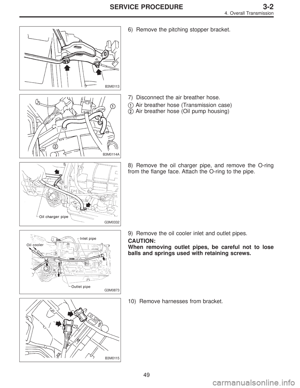
6) Remove the pitching stopper bracket.
B3M0114A
7) Disconnect the air breather hose.
�
1Air breather hose (Transmission case)
�
2Air breather hose (Oil pump housing)
G3M0332
8) Remove the oil charger pipe, and remove the O-ring
from the flange face. Attach the O-ring to the pipe.
G3M0873
9) Remove the oil cooler inlet and outlet pipes.
CAUTION:
When removing outlet pipes, be careful not to lose
balls and springs used with retaining screws.
B3M0115
10) Remove harnesses from bracket.
49
3-2SERVICE PROCEDURE
4. Overall Transmission
Page 856 of 3342
G3M0874
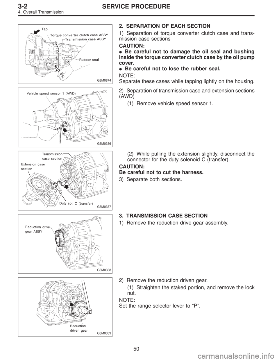
2. SEPARATION OF EACH SECTION
1) Separation of torque converter clutch case and trans-
mission case sections
CAUTION:
�Be careful not to damage the oil seal and bushing
inside the torque converter clutch case by the oil pump
cover.
�Be careful not to lose the rubber seal.
NOTE:
Separate these cases while tapping lightly on the housing.
G3M0336
2) Separation of transmission case and extension sections
(AWD)
(1) Remove vehicle speed sensor 1.
G3M0337
(2) While pulling the extension slightly, disconnect the
connector for the duty solenoid C (transfer).
CAUTION:
Be careful not to cut the harness.
3) Separate both sections.
G3M0338
3. TRANSMISSION CASE SECTION
1) Remove the reduction drive gear assembly.
G3M0339
2) Remove the reduction driven gear.
(1) Straighten the staked portion, and remove the lock
nut.
NOTE:
Set the range selector lever to“P”.
50
3-2SERVICE PROCEDURE
4. Overall Transmission
Page 857 of 3342
G3M0340
(2) Using the ST, extract the reduction driven gear.
ST 899524100 PULLER SET
NOTE:
Drill two holes in the puller.
G3M0341
3) Remove the parking pawl, return spring and shaft.
G3M0342
4) Loosen the taper roller bearing mounting bolts.
G3M0343
5) Place two wooden blocks on the workbench, and stand
the transmission case with its rear end facing down.
CAUTION:
�Be careful not to scratch the rear mating surface of
the transmission case.
�Note that the parking rod and drive pinion protrude
from the mating surface.
G3M0344
6) Remove the oil pan and gasket.
NOTE:
Tap the corners of the oil pan when removing.
51
3-2SERVICE PROCEDURE
4. Overall Transmission
Page 858 of 3342
G3M0345
7) Remove the oil cooler outlet pipe.
CAUTION:
Be careful not to twist the pipe.
G3M0915
8) Disconnect the harness connectors for the solenoids
and duty solenoids and the ground cord.
G3M0299
9) Remove the oil strainer.
CAUTION:
Be careful not to damage O-ring on oil strainer.
G3M0863
10) Remove the control valve body and the two brackets.
52
3-2SERVICE PROCEDURE
4. Overall Transmission


 Place the transmission unit on a work bench, with the
oil pan facing down.
CAUTION:
Be careful not to bend or damage external parts.
G3M0325
2) Remove the d")
 Using the ST, extract the reduction driven gear.
ST 899524100 PULLER SET
NOTE:
Drill two holes in the puller.
G3M0341
3) Remove the parking pawl, return spring and shaft.
G3M0342
4) Loosen")
 Remove the oil cooler outlet pipe.
CAUTION:
Be careful not to twist the pipe.
G3M0915
8) Disconnect the harness connectors for the solenoids
and duty solenoids and the ground cord.
G3M0299")