Page 835 of 3342
G3M0293
(4) Check if there is continuity at equal points when the
select lever is turned 1.5°in both directions from the N
range.
If there is continuity in one direction and the continuity
in the other or if there is continuity at unequal points,
adjust the inhibitor switch.
G3M0294
(1) Loosen the three inhibitor switch securing bolts.
(2) Shift the select lever to the N range.
(3) Insert ST as vertical as possible into the holes in
the inhibitor switch lever and switch body.
ST 499267300 STOPPER PIN
(4) Tighten the three inhibitor switch bolts.
Tightening torque:
3.4±0.5 N⋅m (0.35±0.05 kg-m, 2.5±0.4 ft-lb)
(5) Repeat the above checks. If the inhibitor switch is
determined to be“faulty”, replace it.
G3M0295
3. SENSOR (IN TRANSMISSION)
Check each sensor, solenoid and ground system for short
circuits.
29
3-2SERVICE PROCEDURE
2. On-Car Service
Page 836 of 3342
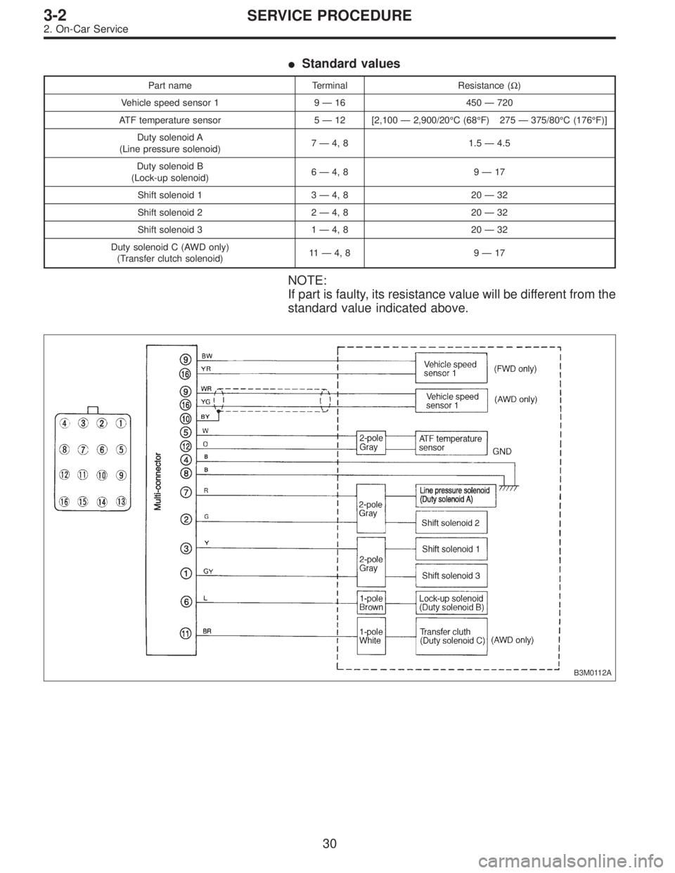
�Standard values
Part name Terminal Resistance (Ω)
Vehicle speed sensor 1 9—16 450—720
ATF temperature sensor 5—12 [2,100—2,900/20°C (68°F) 275—375/80°C (176°F)]
Duty solenoid A
(Line pressure solenoid)7—4, 8 1.5—4.5
Duty solenoid B
(Lock-up solenoid)6—4, 8 9—17
Shift solenoid 1 3—4, 8 20—32
Shift solenoid 2 2—4, 8 20—32
Shift solenoid 3 1—4, 8 20—32
Duty solenoid C (AWD only)
(Transfer clutch solenoid)11—4, 8 9—17
NOTE:
If part is faulty, its resistance value will be different from the
standard value indicated above.
B3M0112A
30
3-2SERVICE PROCEDURE
2. On-Car Service
Page 837 of 3342
G3M0297
C: REMOVAL AND INSTALLATION
1. SHIFT SOLENOID, DUTY SOLENOID AND VALVE
BODY
1) Removal
(1) Clean transmission exterior.
(2) Drain ATF completely.
NOTE:
Tighten ATF drain plug after draining ATF.
Tightening torque:
25±2 N⋅m (2.5±0.2 kg-m, 18.1±1.4 ft-lb)
G3M0861
(3) Remove oil pan and gasket.
NOTE:
Drain oil into a container.
(4) Disconnect solenoid valve connectors.
Remove connectors from clips and disconnect connec-
tors at 4 places.
G3M0862
(5) Remove oil strainer.
Disconnect oil pipe by removing the two bolts, and
remove four bolts and oil strainer.
NOTE:
Be careful because oil flows from oil strainer.
31
3-2SERVICE PROCEDURE
2. On-Car Service
Page 838 of 3342
G3M0863
(6) Remove control valve body and two brackets.
Remove 6 long bolts (Black) and 11 short bolts (Yellow).
NOTE:
�Be careful because oil flows from valve body.
�Be careful not to damage accumulator spring at rear of
control valve.
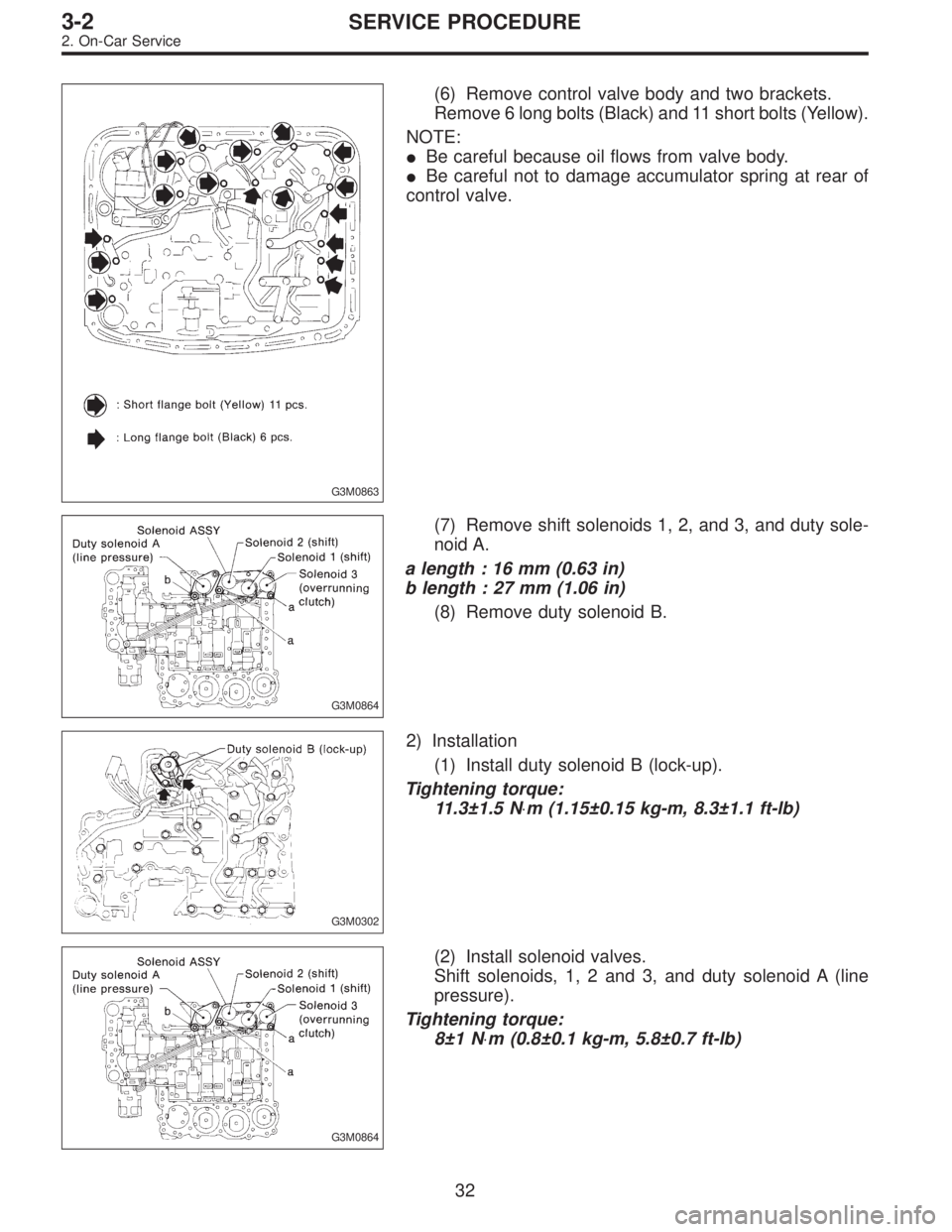
G3M0864
(7) Remove shift solenoids 1, 2, and 3, and duty sole-
noid A.
a length : 16 mm (0.63 in)
b length : 27 mm (1.06 in)
(8) Remove duty solenoid B.
G3M0302
2) Installation
(1) Install duty solenoid B (lock-up).
Tightening torque:
11.3±1.5 N⋅m (1.15±0.15 kg-m, 8.3±1.1 ft-lb)
G3M0864
(2) Install solenoid valves.
Shift solenoids, 1, 2 and 3, and duty solenoid A (line
pressure).
Tightening torque:
8±1 N⋅m (0.8±0.1 kg-m, 5.8±0.7 ft-lb)
32
3-2SERVICE PROCEDURE
2. On-Car Service
Page 839 of 3342
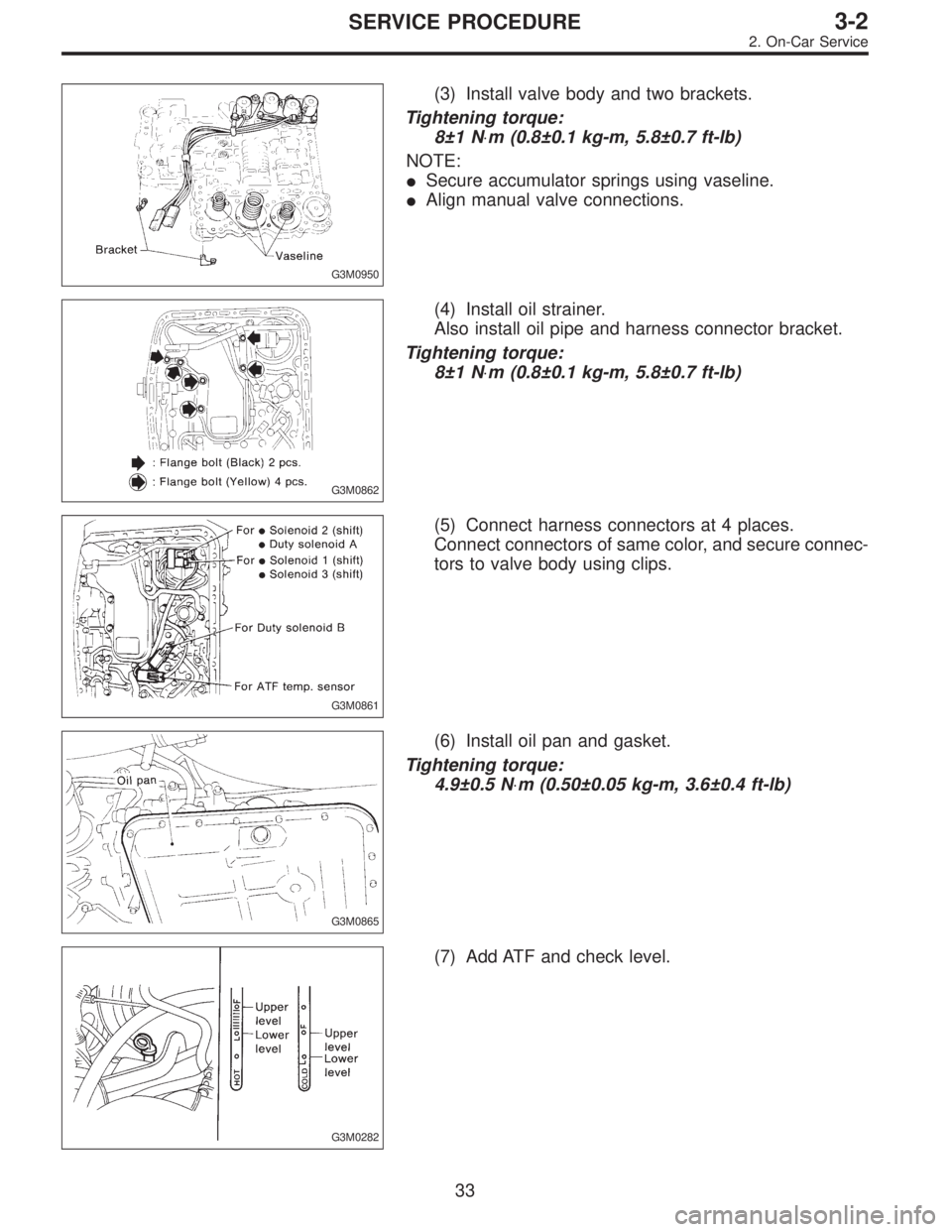
G3M0950
(3) Install valve body and two brackets.
Tightening torque:
8±1 N⋅m (0.8±0.1 kg-m, 5.8±0.7 ft-lb)
NOTE:
�Secure accumulator springs using vaseline.
�Align manual valve connections.
G3M0862
(4) Install oil strainer.
Also install oil pipe and harness connector bracket.
Tightening torque:
8±1 N⋅m (0.8±0.1 kg-m, 5.8±0.7 ft-lb)
G3M0861
(5) Connect harness connectors at 4 places.
Connect connectors of same color, and secure connec-
tors to valve body using clips.
G3M0865
(6) Install oil pan and gasket.
Tightening torque:
4.9±0.5 N⋅m (0.50±0.05 kg-m, 3.6±0.4 ft-lb)
G3M0282
(7) Add ATF and check level.
33
3-2SERVICE PROCEDURE
2. On-Car Service
Page 840 of 3342
G3M0304
2. DUTY SOLENOID C AND TRANSFER VALVE BODY
1) Removal
(1) Remove pitching stopper.
G3M0297
(2) Raise vehicle and drain ATF.
G3M0305
(3) Remove front exhaust pipe.
Disconnect oxygen sensor connector, and remove
exhaust pipe.
G3M0782
(4) Remove propeller shaft.
NOTE:
Before removing propeller shaft, scribe matching marks on
propeller shaft and rear differential coupling.
G3M0306
(5) Remove rear crossmember.
�Support transmission using a transmission jack and
raise slightly.
�Remove bolts and nuts as shown in Figure.
34
3-2SERVICE PROCEDURE
2. On-Car Service
Page 841 of 3342
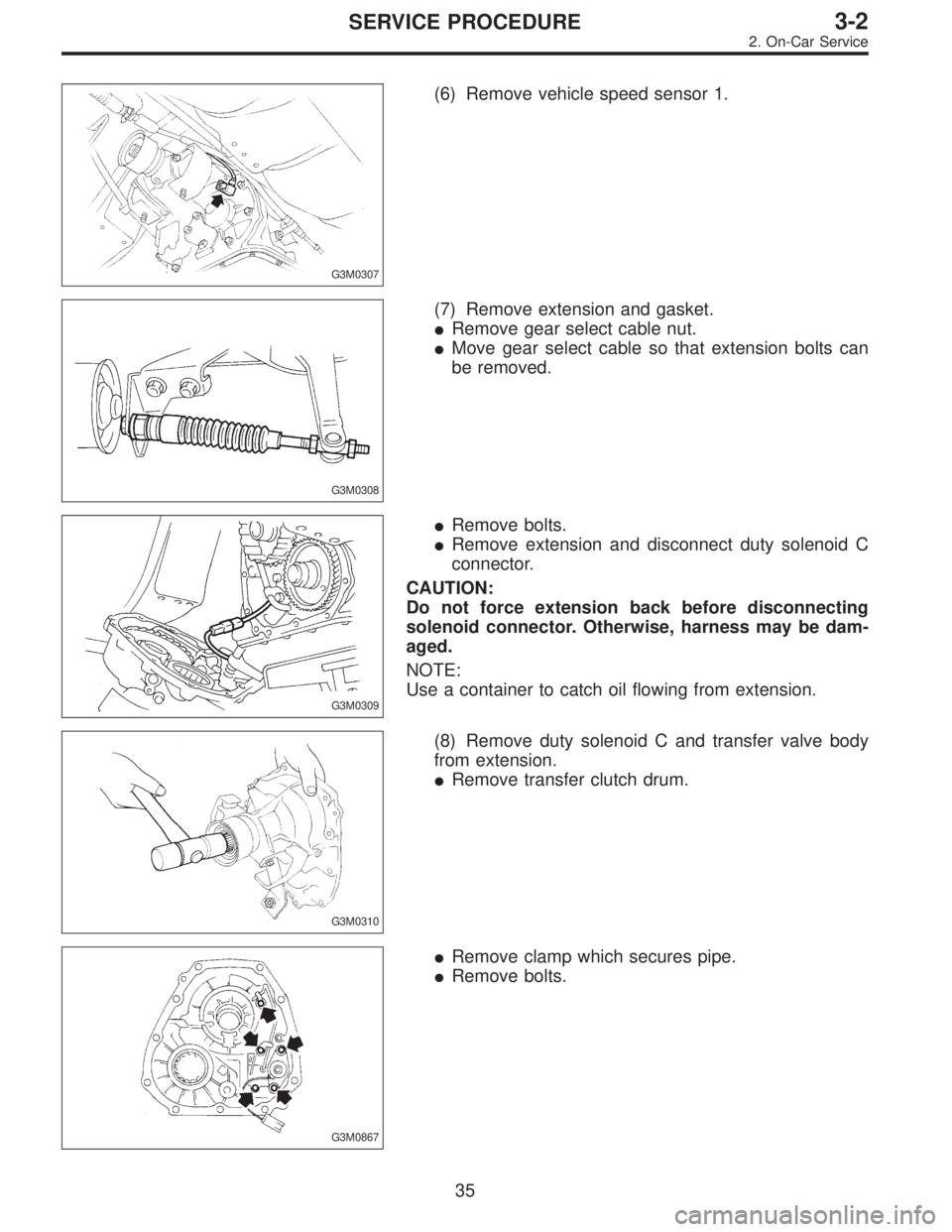
G3M0307
(6) Remove vehicle speed sensor 1.
G3M0308
(7) Remove extension and gasket.
�Remove gear select cable nut.
�Move gear select cable so that extension bolts can
be removed.
G3M0309
�Remove bolts.
�Remove extension and disconnect duty solenoid C
connector.
CAUTION:
Do not force extension back before disconnecting
solenoid connector. Otherwise, harness may be dam-
aged.
NOTE:
Use a container to catch oil flowing from extension.
G3M0310
(8) Remove duty solenoid C and transfer valve body
from extension.
�Remove transfer clutch drum.
G3M0867
�Remove clamp which secures pipe.
�Remove bolts.
35
3-2SERVICE PROCEDURE
2. On-Car Service
Page 842 of 3342
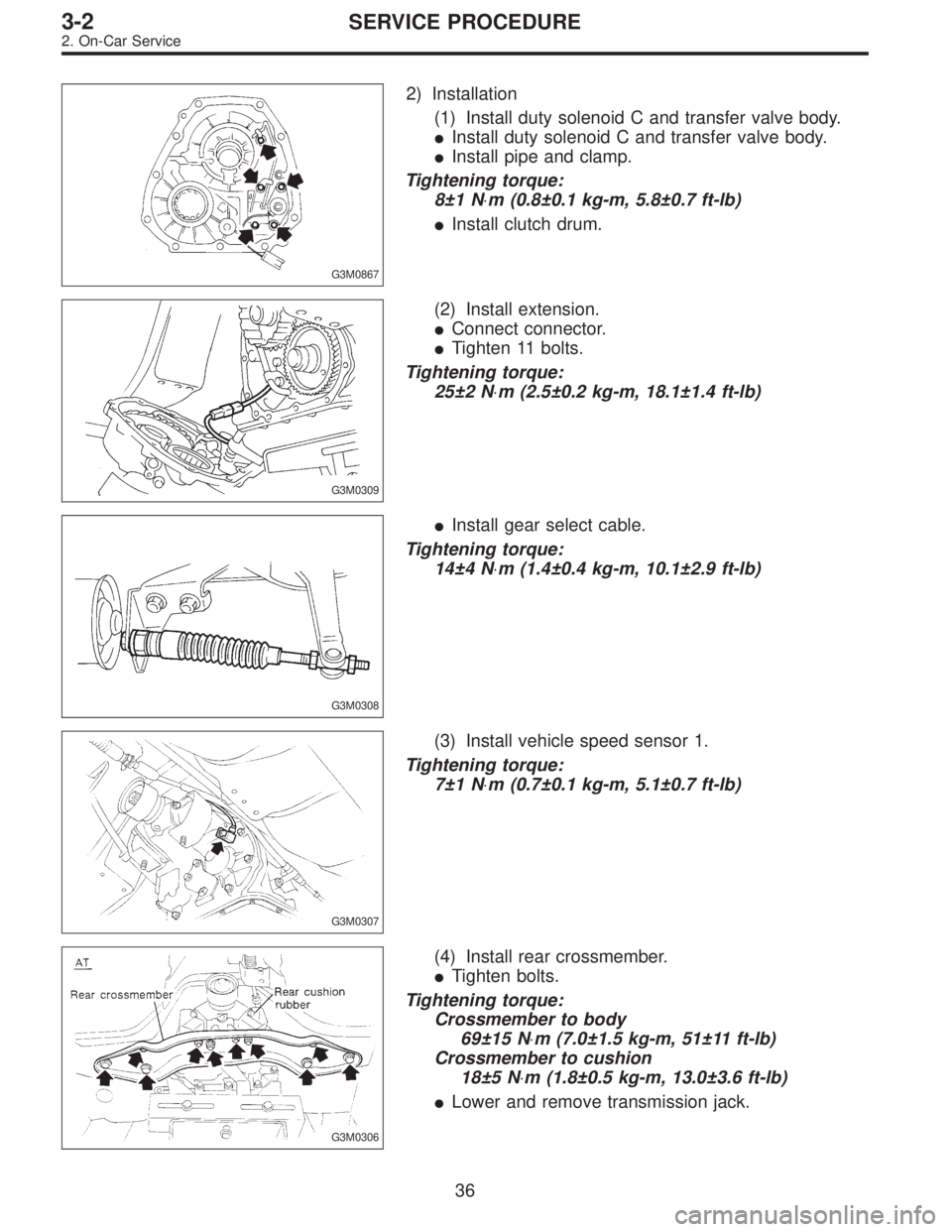
G3M0867
2) Installation
(1) Install duty solenoid C and transfer valve body.
�Install duty solenoid C and transfer valve body.
�Install pipe and clamp.
Tightening torque:
8±1 N⋅m (0.8±0.1 kg-m, 5.8±0.7 ft-lb)
�Install clutch drum.
G3M0309
(2) Install extension.
�Connect connector.
�Tighten 11 bolts.
Tightening torque:
25±2 N⋅m (2.5±0.2 kg-m, 18.1±1.4 ft-lb)
G3M0308
�Install gear select cable.
Tightening torque:
14±4 N⋅m (1.4±0.4 kg-m, 10.1±2.9 ft-lb)
G3M0307
(3) Install vehicle speed sensor 1.
Tightening torque:
7±1 N⋅m (0.7±0.1 kg-m, 5.1±0.7 ft-lb)
G3M0306
(4) Install rear crossmember.
�Tighten bolts.
Tightening torque:
Crossmember to body
69±15 N⋅m (7.0±1.5 kg-m, 51±11 ft-lb)
Crossmember to cushion
18±5 N⋅m (1.8±0.5 kg-m, 13.0±3.6 ft-lb)
�Lower and remove transmission jack.
36
3-2SERVICE PROCEDURE
2. On-Car Service
 Check if there is continuity at equal points when the
select lever is turned 1.5°in both directions from the N
range.
If there is continuity in one direction and the continuity
in the oth")
 Removal
(1) Clean transmission exterior.
(2) Drain ATF completely.
NOTE:
Tighten ATF drain plug after draining AT")
 Removal
(1) Remove pitching stopper.
G3M0297
(2) Raise vehicle and drain ATF.
G3M0305
(3) Remove front exhaust pipe.
Disconnect oxygen sensor conn")