Page 875 of 3342
G3M0409
13) Install the one-way clutch outer race.
NOTE:
Make sure the forward clutch splines are engaged cor-
rectly.
B3M0117A
14) Assemble the rear internal gear.
(1) Join the thrust needle bearing and thrust washer to
the gear with vaseline, and install the gear while rotat-
ing it.
(2) Securely engage the bearing with the dog of the
overrunning clutch hub.
CAUTION:
Install thrust needle bearing in the correct direction.
NOTE:
Installation is complete when the snap ring top surface of
the forward clutch drum recedes approximately 3.5 mm
(0.138 in).
G3M0890
15) Install the rear planetary carrier.
Attach the thrust needle bearing to the inside of the carrier
with vaseline. Then install the carrier while rotating slowly.
CAUTION:
Install thrust needle bearing in the correct direction.
G3M0891
16) Install the rear sun gear.
NOTE:
Install the gear with the oil groove facing up.
69
3-2SERVICE PROCEDURE
4. Overall Transmission
Page 876 of 3342

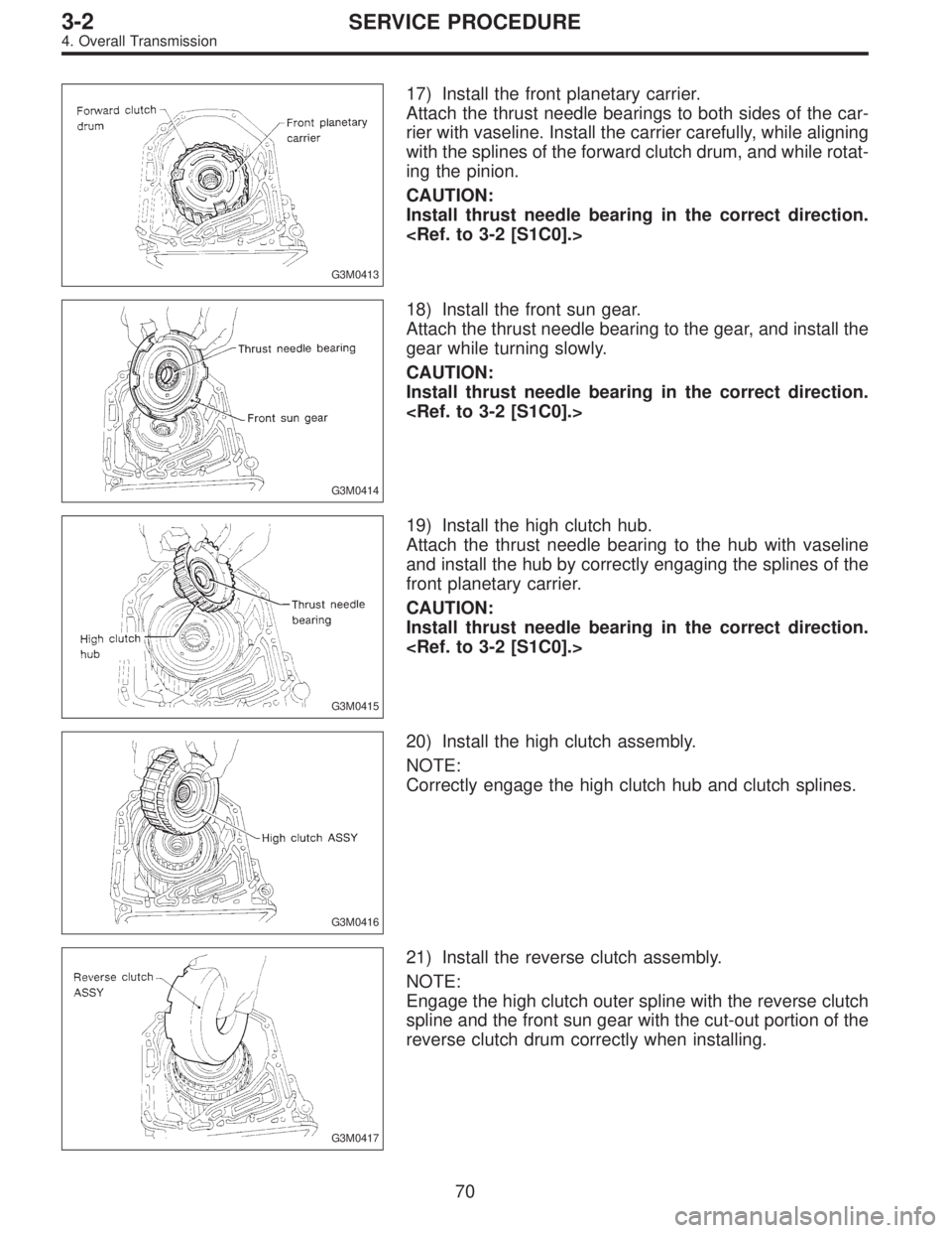
G3M0413
17) Install the front planetary carrier.
Attach the thrust needle bearings to both sides of the car-
rier with vaseline. Install the carrier carefully, while aligning
with the splines of the forward clutch drum, and while rotat-
ing the pinion.
CAUTION:
Install thrust needle bearing in the correct direction.
G3M0414
18) Install the front sun gear.
Attach the thrust needle bearing to the gear, and install the
gear while turning slowly.
CAUTION:
Install thrust needle bearing in the correct direction.
G3M0415
19) Install the high clutch hub.
Attach the thrust needle bearing to the hub with vaseline
and install the hub by correctly engaging the splines of the
front planetary carrier.
CAUTION:
Install thrust needle bearing in the correct direction.
G3M0416
20) Install the high clutch assembly.
NOTE:
Correctly engage the high clutch hub and clutch splines.
G3M0417
21) Install the reverse clutch assembly.
NOTE:
Engage the high clutch outer spline with the reverse clutch
spline and the front sun gear with the cut-out portion of the
reverse clutch drum correctly when installing.
70
3-2SERVICE PROCEDURE
4. Overall Transmission
Page 877 of 3342
G3M0418
22) Install the brake band.
CAUTION:
Be careful not to damage the brake band when install-
ing.
NOTE:
Install the strut to the band servo piston stem. Then tighten
it temporarily to avoid tilting the band.
23) Adjustment of total end play and reverse clutch end
play
(1) Measure the distance from the transmission case
mating surface to the recessed portion of the high
clutch drum“L”, and the distance to the top surface of
the reverse clutch drum“M”.
G3M0419
71
3-2SERVICE PROCEDURE
4. Overall Transmission
Page 878 of 3342
(2) Measure the distance from the oil pump housing
mating surface to the top surface of the oil pump cover
with needle bearing, and to the thrust surface of the
reverse clutch.
G3M0420
(3) Equation for calculation
�Total end play
Unit: mm
C = (L + 0.4)��
C : Clearance between concave portion of high clutch
and end of clutch drum support
L : Length from case mating surface to concave portion
of high clutch
0.4 : Gasket thickness
�: Height from housing mating surface to upper surface
of clutch drum support
Select suitable bearing race from
among those listed in this table
so that clearance C is in the 0.25—
0.55 mm (0.0098—0.0217 in) range.Part No. Thickness mm (in)
803031021
803031022
803031023
803031024
803031025
803031026
8030310270.8 (0.031)
1.0 (0.039)
1.2 (0.047)
1.4 (0.055)
1.6 (0.063)
1.8 (0.071)
2.0 (0.079)
72
3-2SERVICE PROCEDURE
4. Overall Transmission
Page 879 of 3342

�Reverse clutch end play
Unit: mm
C = (M + 0.4)�m
C : Clearance between oil pump housing hose and end
of reverse clutch
M : Distance from case mating surface to upper surface
of reverse clutch
0.4 : Gasket thickness
m : Height from housing mating surface to thrust-receiv-
ing area of reverse clutch
Select suitable thrust washer from
among those listed in this table so that
clearance C is in the 0.55—0.90 mm
(0.0217—0.0354 in) range.Part No. Thickness mm (in)
31299AA000
31299AA010
31299AA020
31299AA030
31299AA040
31299AA050
31299AA0600.7 (0.028)
0.9 (0.035)
1.1 (0.043)
1.3 (0.051)
1.5 (0.059)
1.7 (0.067)
1.9 (0.075)
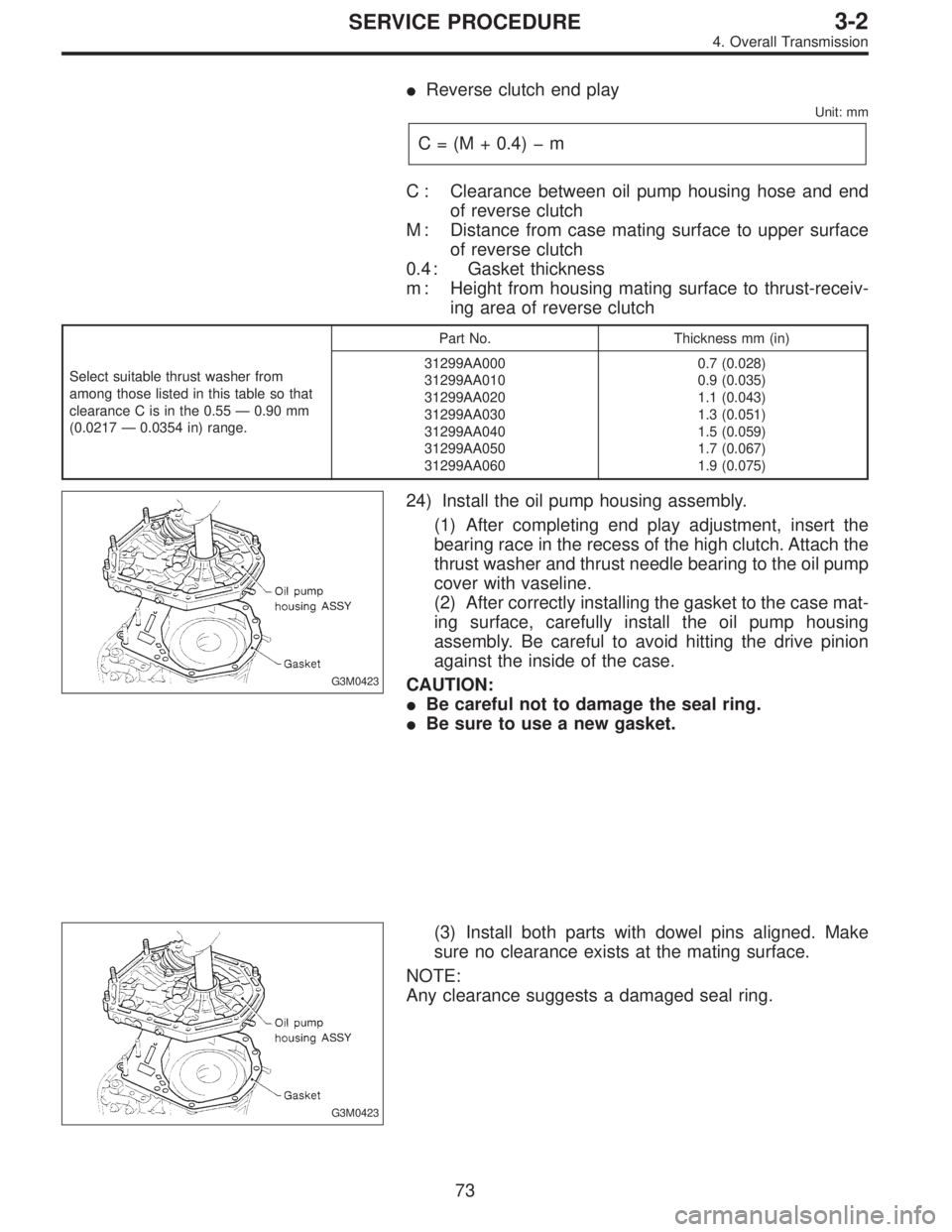
G3M0423
24) Install the oil pump housing assembly.
(1) After completing end play adjustment, insert the
bearing race in the recess of the high clutch. Attach the
thrust washer and thrust needle bearing to the oil pump
cover with vaseline.
(2) After correctly installing the gasket to the case mat-
ing surface, carefully install the oil pump housing
assembly. Be careful to avoid hitting the drive pinion
against the inside of the case.
CAUTION:
�Be careful not to damage the seal ring.
�Be sure to use a new gasket.
G3M0423
(3) Install both parts with dowel pins aligned. Make
sure no clearance exists at the mating surface.
NOTE:
Any clearance suggests a damaged seal ring.
73
3-2SERVICE PROCEDURE
4. Overall Transmission
Page 880 of 3342

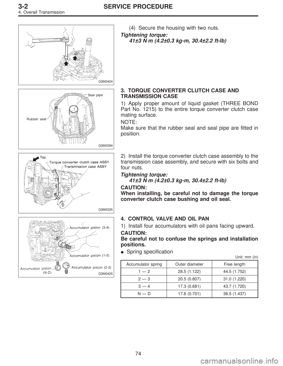
G3M0424
(4) Secure the housing with two nuts.
Tightening torque:
41±3 N⋅m (4.2±0.3 kg-m, 30.4±2.2 ft-lb)
G3M0394
3. TORQUE CONVERTER CLUTCH CASE AND
TRANSMISSION CASE
1) Apply proper amount of liquid gasket (THREE BOND
Part No. 1215) to the entire torque converter clutch case
mating surface.
NOTE:
Make sure that the rubber seal and seal pipe are fitted in
position.
G3M0335
2) Install the torque converter clutch case assembly to the
transmission case assembly, and secure with six bolts and
four nuts.
Tightening torque:
41±3 N⋅m (4.2±0.3 kg-m, 30.4±2.2 ft-lb)
CAUTION:
When installing, be careful not to damage the torque
converter clutch case bushing and oil seal.
G3M0425
4. CONTROL VALVE AND OIL PAN
1) Install four accumulators with oil pans facing upward.
CAUTION:
Be careful not to confuse the springs and installation
positions.
�Spring specification
Unit: mm (in)
Accumulator spring Outer diameter Free length
1—2 28.5 (1.122) 44.5 (1.752)
2—3 20.5 (0.807) 31.0 (1.220)
3—4 17.3 (0.681) 43.7 (1.720)
N—D 17.8 (0.701) 36.5 (1.437)
74
3-2SERVICE PROCEDURE
4. Overall Transmission
Page 881 of 3342
G3M0367
2) Install and route the transmission harness.
CAUTION:
Be careful not to damage the harness.
B3M0418A
3) Install the control valve assembly.
(1) Set the select lever in range“2”.
(2) Install the two brackets, ATF temperature sensor
and the control valve by engaging the manual valve and
manual lever, then tighten the 17 bolts.
Tightening torque:
8±1 N⋅m (0.8±0.1 kg-m, 5.8±0.7 ft-lb)
CAUTION:
�Be careful not to pinch the harness roll the gasket.
�Tighten the control valve mounting bolts evenly.
B3M0419A
4) Install the oil strainer to the control valve. Be careful not
to cut or break the O-ring. Then tighten four bolts.
Tightening torque:
8±1 N⋅m (0.8±0.1 kg-m, 5.8±0.7 ft-lb)
B3M0420A
5) Secure four connectors.
75
3-2SERVICE PROCEDURE
4. Overall Transmission
Page 882 of 3342

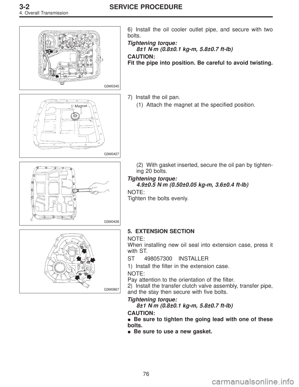
G3M0345
6) Install the oil cooler outlet pipe, and secure with two
bolts.
Tightening torque:
8±1 N⋅m (0.8±0.1 kg-m, 5.8±0.7 ft-lb)
CAUTION:
Fit the pipe into position. Be careful to avoid twisting.
G3M0427
7) Install the oil pan.
(1) Attach the magnet at the specified position.
G3M0428
(2) With gasket inserted, secure the oil pan by tighten-
ing 20 bolts.
Tightening torque:
4.9±0.5 N⋅m (0.50±0.05 kg-m, 3.6±0.4 ft-lb)
NOTE:
Tighten the bolts evenly.
G3M0867
5. EXTENSION SECTION
NOTE:
When installing new oil seal into extension case, press it
with ST.
ST 498057300 INSTALLER
1) Install the filter in the extension case.
NOTE:
Pay attention to the orientation of the filter.
2) Install the transfer clutch valve assembly, transfer pipe,
and the stay then secure with five bolts.
Tightening torque:
8±1 N⋅m (0.8±0.1 kg-m, 5.8±0.7 ft-lb)
CAUTION:
�Be sure to tighten the going lead with one of these
bolts.
�Be sure to use a new gasket.
76
3-2SERVICE PROCEDURE
4. Overall Transmission