Page 891 of 3342

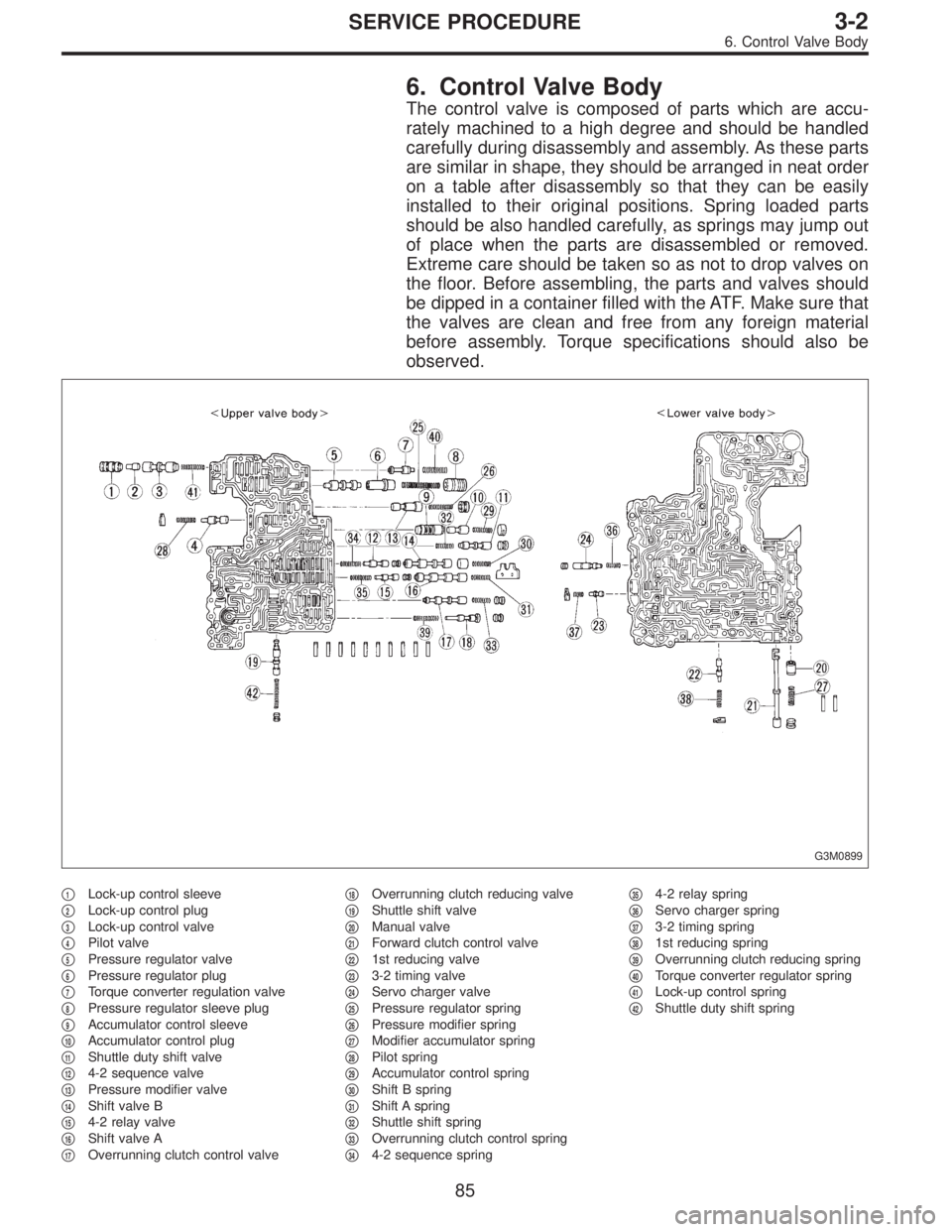
6. Control Valve Body
The control valve is composed of parts which are accu-
rately machined to a high degree and should be handled
carefully during disassembly and assembly. As these parts
are similar in shape, they should be arranged in neat order
on a table after disassembly so that they can be easily
installed to their original positions. Spring loaded parts
should be also handled carefully, as springs may jump out
of place when the parts are disassembled or removed.
Extreme care should be taken so as not to drop valves on
the floor. Before assembling, the parts and valves should
be dipped in a container filled with the ATF. Make sure that
the valves are clean and free from any foreign material
before assembly. Torque specifications should also be
observed.
G3M0899
�1Lock-up control sleeve
�
2Lock-up control plug
�
3Lock-up control valve
�
4Pilot valve
�
5Pressure regulator valve
�
6Pressure regulator plug
�
7Torque converter regulation valve
�
8Pressure regulator sleeve plug
�
9Accumulator control sleeve
�
10Accumulator control plug
�
11Shuttle duty shift valve
�
124-2 sequence valve
�
13Pressure modifier valve
�
14Shift valve B
�
154-2 relay valve
�
16Shift valve A
�
17Overrunning clutch control valve�
18Overrunning clutch reducing valve
�
19Shuttle shift valve
�
20Manual valve
�
21Forward clutch control valve
�
221st reducing valve
�
233-2 timing valve
�
24Servo charger valve
�
25Pressure regulator spring
�
26Pressure modifier spring
�
27Modifier accumulator spring
�
28Pilot spring
�
29Accumulator control spring
�
30Shift B spring
�
31Shift A spring
�
32Shuttle shift spring
�
33Overrunning clutch control spring
�
344-2 sequence spring�
354-2 relay spring
�
36Servo charger spring
�
373-2 timing spring
�
381st reducing spring
�
39Overrunning clutch reducing spring
�
40Torque converter regulator spring
�
41Lock-up control spring
�
42Shuttle duty shift spring
85
3-2SERVICE PROCEDURE
6. Control Valve Body
Page 892 of 3342

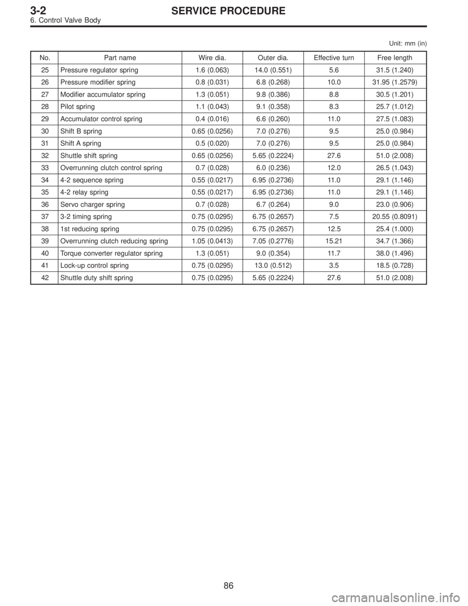
Unit: mm (in)
No. Part name Wire dia. Outer dia. Effective turn Free length
25 Pressure regulator spring 1.6 (0.063) 14.0 (0.551) 5.6 31.5 (1.240)
26 Pressure modifier spring 0.8 (0.031) 6.8 (0.268) 10.0 31.95 (1.2579)
27 Modifier accumulator spring 1.3 (0.051) 9.8 (0.386) 8.8 30.5 (1.201)
28 Pilot spring 1.1 (0.043) 9.1 (0.358) 8.3 25.7 (1.012)
29 Accumulator control spring 0.4 (0.016) 6.6 (0.260) 11.0 27.5 (1.083)
30 Shift B spring 0.65 (0.0256) 7.0 (0.276) 9.5 25.0 (0.984)
31 Shift A spring 0.5 (0.020) 7.0 (0.276) 9.5 25.0 (0.984)
32 Shuttle shift spring 0.65 (0.0256) 5.65 (0.2224) 27.6 51.0 (2.008)
33 Overrunning clutch control spring 0.7 (0.028) 6.0 (0.236) 12.0 26.5 (1.043)
34 4-2 sequence spring 0.55 (0.0217) 6.95 (0.2736) 11.0 29.1 (1.146)
35 4-2 relay spring 0.55 (0.0217) 6.95 (0.2736) 11.0 29.1 (1.146)
36 Servo charger spring 0.7 (0.028) 6.7 (0.264) 9.0 23.0 (0.906)
37 3-2 timing spring 0.75 (0.0295) 6.75 (0.2657) 7.5 20.55 (0.8091)
38 1st reducing spring 0.75 (0.0295) 6.75 (0.2657) 12.5 25.4 (1.000)
39 Overrunning clutch reducing spring 1.05 (0.0413) 7.05 (0.2776) 15.21 34.7 (1.366)
40 Torque converter regulator spring 1.3 (0.051) 9.0 (0.354) 11.7 38.0 (1.496)
41 Lock-up control spring 0.75 (0.0295) 13.0 (0.512) 3.5 18.5 (0.728)
42 Shuttle duty shift spring 0.75 (0.0295) 5.65 (0.2224) 27.6 51.0 (2.008)
86
3-2SERVICE PROCEDURE
6. Control Valve Body
Page 893 of 3342
G3M0864
A: DISASSEMBLY
1) Remove the following parts from the upper valve body.
(1) Solenoid assembly (shift 1-2-3)
(2) Duty solenoid A (line pressure)
B3M0405A
2) Remove the following parts from the lower valve body.
(1) Duty solenoid B (lock-up)
(2) Bracket
3) Separate the upper valve body and lower valve body.
G3M0901
CAUTION:
�Do not lose the nine (9) steel balls contained in the
upper valve body.
�Do not lose an orifice and a strainer contained in the
lower valve body.
NOTE:
Remove the upper-lower valve body tightening bolts. Then
remove two locating bolts. (
)
During ordinary servicing, clean the control valve bodies in
this condition, without further disassembly.
In the event of a seized clutch or other problem, disas-
semble the control valve bodies further, and clean the com-
ponent parts.
B: INSPECTION
Make sure that each component is free of harmful gouges,
cuts, or dust.
87
3-2SERVICE PROCEDURE
6. Control Valve Body
Page 894 of 3342
G3M0902
C: ASSEMBLY
1) Install the nine steel balls to the upper valve body.
G3M0903
2) From under upper valve body, install two bolts using
washers and position upper separator gasket.
G3M0904
3) Install the orifice check valve, orifice check spring and
filter to the lower valve body.
G3M0905
4) Install lower separate gasket and separate plate on
lower body in that order, then temporarily tighten three
support plates and two brackets.
88
3-2SERVICE PROCEDURE
6. Control Valve Body
Page 895 of 3342
G3M0906
5) Temporarily assemble lower valve body to upper valve
body.
CAUTION:
Be careful not to drop the upper body interior steel
ball, or the lower body interior filter, orifice check
spring, or orifice check valve.
B3M0406A
6) Install the duty solenoid B and the four brackets.
7) Tighten twenty seven bolts & washers and two reamer
bolts.
Tightening torque:
T1: 8±1 N⋅m (0.8±0.1 kg-m, 5.8±0.7 ft-lb)
T2: 11.3±1.5 N⋅m (1.15±0.15 kg-m, 8.3±1.1 ft-lb)
Unit: mm (in)
abcde
Length 70 (2.76) 50 (1.97) 33 (1.30) 27 (1.06) 28 (1.10)
Numbers 2 6 16 1 2
G3M0864
8) Install the shift solenoid and duty solenoid A.
a length : 16 mm (0.63 in)
b length : 27 mm (1.06 in)
Tightening torque:
8±1 N⋅m (0.8±0.1 kg-m, 5.8±0.7 ft-lb)
G3M0445
7. Oil Pump Assembly
A: DISASSEMBLY
1) Remove the oil seal retainer.
Also remove the O-ring and oil seal (air breather).
89
3-2SERVICE PROCEDURE
6. Control Valve Body - 7. Oil Pump Assembly
Page 896 of 3342
G3M0446
2) Remove the oil pump cover.
NOTE:
Lightly tap the end of the stator shaft to remove the cover.
G3M0447
3) Remove the retainer and return spring. Then remove
the rotor, two vane rings and nine vanes.
G3M0448
4) Remove the cam ring and control piston.
Also remove the O-ring, friction ring, two side seals, and
plain seal.
G3M0449
5) Remove two seal rings (R) and two seal rings (H).
B: INSPECTION
1) Make sure that each component is free of harmful
gouges, cuts, and dust.
90
3-2SERVICE PROCEDURE
7. Oil Pump Assembly
Page 897 of 3342

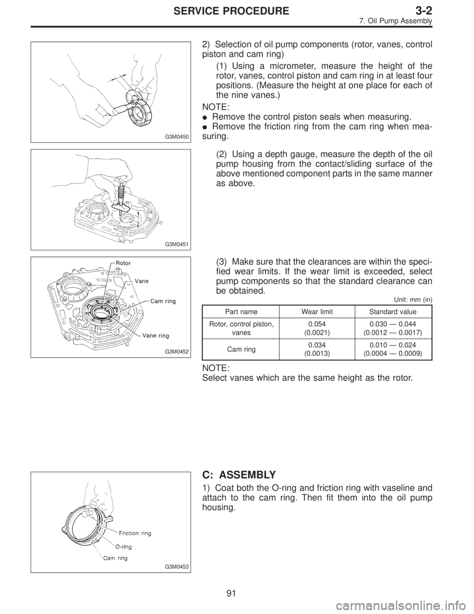
G3M0450
2) Selection of oil pump components (rotor, vanes, control
piston and cam ring)
(1) Using a micrometer, measure the height of the
rotor, vanes, control piston and cam ring in at least four
positions. (Measure the height at one place for each of
the nine vanes.)
NOTE:
�Remove the control piston seals when measuring.
�Remove the friction ring from the cam ring when mea-
suring.
G3M0451
(2) Using a depth gauge, measure the depth of the oil
pump housing from the contact/sliding surface of the
above mentioned component parts in the same manner
as above.
G3M0452
(3) Make sure that the clearances are within the speci-
fied wear limits. If the wear limit is exceeded, select
pump components so that the standard clearance can
be obtained.
Unit: mm (in)
Part name Wear limit Standard value
Rotor, control piston,
vanes0.054
(0.0021)0.030—0.044
(0.0012—0.0017)
Cam ring0.034
(0.0013)0.010—0.024
(0.0004—0.0009)
NOTE:
Select vanes which are the same height as the rotor.
G3M0453
C: ASSEMBLY
1) Coat both the O-ring and friction ring with vaseline and
attach to the cam ring. Then fit them into the oil pump
housing.
91
3-2SERVICE PROCEDURE
7. Oil Pump Assembly
Page 898 of 3342
G3M0454
2) Install the vane ring, rotor and vanes into the housing
in this sequence.
G3M0455
3) Install the return spring and retainer between the hous-
ing and cam ring.
G3M0456
4) Install the control piston to the oil pump housing.
NOTE:
Fit the seal in the piston groove, with the red seals facing
the top side. (Two side seals and one plain seal are
attached.)
5) Set the rotor at the center of the housing bore. Apply
ATF abundantly to each rotary portion.
G3M0446
6) Install the oil pump cover.
Tightening torque:
25±2 N⋅m (2.5±0.2 kg-m, 18.1±1.4 ft-lb)
NOTE:
�Align both pivots with the pivot holes of the cover, and
install the cover being careful not to apply undue force to
the pivots.
�After assembling, turn the oil pump shaft to check for
smooth rotation of the rotor.
G3M0449
NOTE:
�Install the oil seal retainer and seal rings (R) and (H)
after adjusting the drive pinion backlash and tooth contact.
92
3-2SERVICE PROCEDURE
7. Oil Pump Assembly