Page 899 of 3342
G3M0458
8. Drive Pinion Shaft
A: DISASSEMBLY
1) Straighten the staked portion of the lock nut, and
remove the lock nut while locking the rear spline portion of
the shaft with ST1 and ST2. Then pull off the drive pinion
collar.
ST1 498937100 HOLDER
ST2 499787100 WRENCH
NOTE:
Remove the O-ring
G3M0459
2) Using a press, separate the rear roller bearing and
outer race from the shaft.
G3M0460
3) Using a press and ST, separate the front roller bearing
from the shaft.
ST 498517000 REPLACER
B: INSPECTION
Make sure that all component parts are free of harmful
cuts, gouges, and other faults.
93
3-2SERVICE PROCEDURE
8. Drive Pinion Shaft
Page 900 of 3342
 Measure dimension“A”of the drive pinion shaft.
G3M0462
2) Using a press, force-fit the roller bearing in position.
CAUTION:
Do not change the relative positions of the outer")
G3M0461
C: ASSEMBLY
1) Measure dimension“A”of the drive pinion shaft.
G3M0462
2) Using a press, force-fit the roller bearing in position.
CAUTION:
Do not change the relative positions of the outer race
and bearing cone.
3) After fitting the O-ring to the shaft, attach the drive pin-
ion collar to the shaft.
CAUTION:
Be careful not to damage the O-ring.
G3M0908
4) Tighten the lock washer and lock nut with ST1.
ST1 498937100 HOLDER
Actual tightening torque:
113±5 N⋅m (11.5±0.5 kg-m, 83.2±3.6 ft-lb)
NOTE:
�Pay attention to the orientation of lock washer.
�Tightening torque using torque wrench is determined by
the following equation:
T
1=72.2L + 72.2xT
T: Actual tightening torque
�Install ST2 to torque wrench as straight as possible.
ST2 499787100 WRENCH
G3M0464
5) Measure the starting torque of the bearing.
Make sure the starting torque is within the specified range.
If out of the allowable range, replace the roller bearing.
Starting torque:
0.3—2.0 N⋅m(3—20 kg-cm, 2.6—17.4 ft-lb)
94
3-2SERVICE PROCEDURE
8. Drive Pinion Shaft
Page 901 of 3342
G3M0465
6) Stake the lock nut securely at two places.
7) Measure dimension“B”of the drive pinion shaft.
8) Determine the thickness t (mm) of the drive pinion shim.
t = 6.5±0.0625 � (B � A)
NOTE:
The number of shims must be three or less.
�Available drive pinion shimsPart No. Thickness mm (in)
31451AA050
31451AA060
31451AA070
31451AA080
31451AA090
31451AA1000.150 (0.0059)
0.175 (0.0069)
0.200 (0.0079)
0.225 (0.0089)
0.250 (0.0098)
0.275 (0.0108)
95
3-2SERVICE PROCEDURE
8. Drive Pinion Shaft
Page 902 of 3342
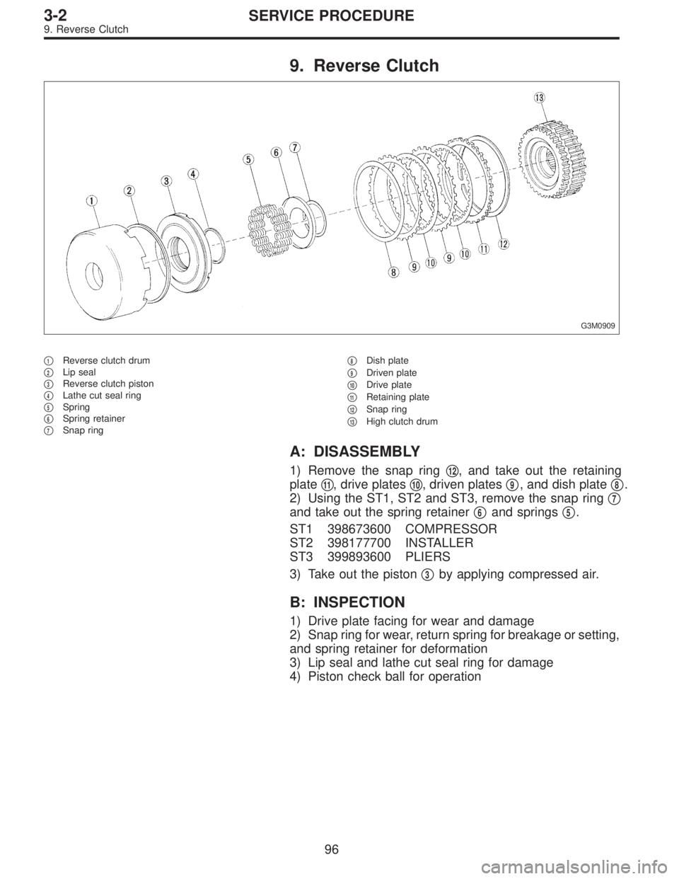
9. Reverse Clutch
G3M0909
�1Reverse clutch drum
�
2Lip seal
�
3Reverse clutch piston
�
4Lathe cut seal ring
�
5Spring
�
6Spring retainer
�
7Snap ring�
8Dish plate
�
9Driven plate
�
10Drive plate
�
11Retaining plate
�
12Snap ring
�
13High clutch drum
A: DISASSEMBLY
1) Remove the snap ring�12, and take out the retaining
plate�
11, drive plates�10, driven plates�9, and dish plate�8.
2) Using the ST1, ST2 and ST3, remove the snap ring�
7
and take out the spring retainer�6and springs�5.
ST1 398673600 COMPRESSOR
ST2 398177700 INSTALLER
ST3 399893600 PLIERS
3) Take out the piston�
3by applying compressed air.
B: INSPECTION
1) Drive plate facing for wear and damage
2) Snap ring for wear, return spring for breakage or setting,
and spring retainer for deformation
3) Lip seal and lathe cut seal ring for damage
4) Piston check ball for operation
96
3-2SERVICE PROCEDURE
9. Reverse Clutch
Page 903 of 3342

C: ASSEMBLY
G3M0909
�1Reverse clutch drum
�
2Lip seal
�
3Reverse clutch piston
�
4Lathe cut seal ring�
5Spring
�
6Spring retainer
�
7Snap ring�
8Dish plate
�
9Driven plate
�
10Drive plate�
11Retaining plate
�
12Snap ring
�
13High clutch drum
1) Using the ST1, ST2 and ST3 as those used in
disassembling, assemble piston�
3the springs�5, spring
retainer�
6and snap ring�7.
ST1 398673600 COMPRESSOR
ST2 398177700 INSTALLER
ST3 399893600 PLIERS
2) Assemble the dish plate�
8, driven plates�9, drive
plates�
10and retaining plate�11in that order and attach the
snap ring�
12.
NOTE:
Pay attention to the orientation of the dish plate.
3) Checking operation:
Apply compressed air intermittently to the oil hole, and
check the reverse clutch for smooth operation.
4) Measuring clearance (Retaining plate selection):
Standard value:
0.5—0.8 mm (0.020—0.031 in)
Allowable limit:
1.2 mm (0.047 in)
NOTE:
Before measuring clearance, place the same thickness of
shim on both sides to prevent retaining plate from tilting.
�Available retaining platesPart No. Thickness mm (in)
31567AA350
31567AA360
31567AA370
31567AA380
31567AA390
31567AA4004.6 (0.181)
4.8 (0.189)
5.0 (0.197)
5.2 (0.205)
5.4 (0.213)
5.6 (0.220)
97
3-2SERVICE PROCEDURE
9. Reverse Clutch
Page 904 of 3342
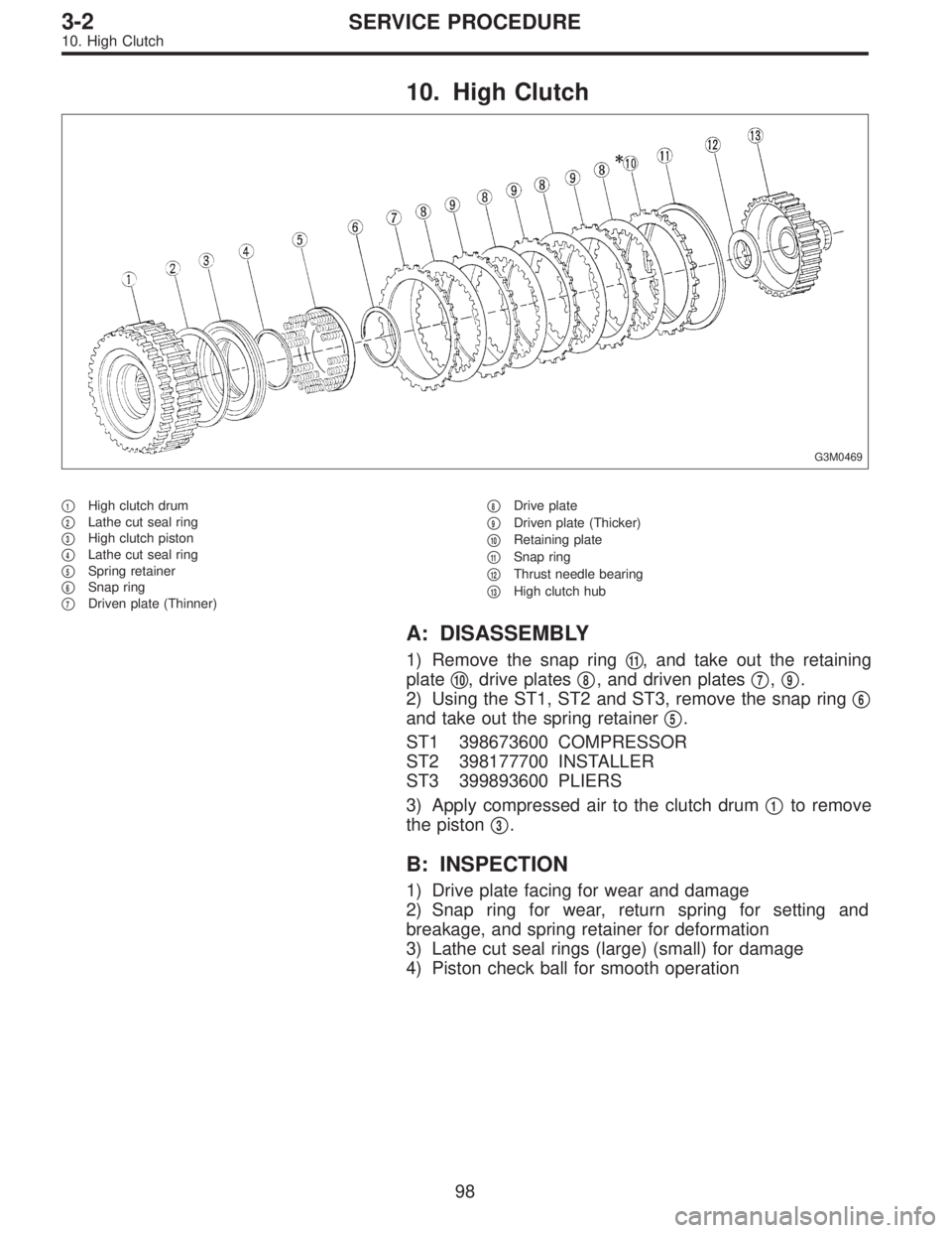
10. High Clutch
G3M0469
�1High clutch drum
�
2Lathe cut seal ring
�
3High clutch piston
�
4Lathe cut seal ring
�
5Spring retainer
�
6Snap ring
�
7Driven plate (Thinner)�
8Drive plate
�
9Driven plate (Thicker)
�
10Retaining plate
�
11Snap ring
�
12Thrust needle bearing
�
13High clutch hub
A: DISASSEMBLY
1) Remove the snap ring�11, and take out the retaining
plate�
10, drive plates�8, and driven plates�7,�9.
2) Using the ST1, ST2 and ST3, remove the snap ring�
6
and take out the spring retainer�5.
ST1 398673600 COMPRESSOR
ST2 398177700 INSTALLER
ST3 399893600 PLIERS
3) Apply compressed air to the clutch drum�
1to remove
the piston�
3.
B: INSPECTION
1) Drive plate facing for wear and damage
2) Snap ring for wear, return spring for setting and
breakage, and spring retainer for deformation
3) Lathe cut seal rings (large) (small) for damage
4) Piston check ball for smooth operation
98
3-2SERVICE PROCEDURE
10. High Clutch
Page 905 of 3342
�
8Drive plate
�
9Driven plate (Thic")
C: ASSEMBLY
G3M0469
�1High clutch drum
�
2Lathe cut seal ring
�
3High clutch piston
�
4Lathe cut seal ring
�
5Spring retainer
�
6Snap ring
�
7Driven plate (Thinner)�
8Drive plate
�
9Driven plate (Thicker)
�
10Retaining plate
�
11Snap ring
�
12Thrust needle bearing
�
13High clutch hub
1) Using the ST1, ST2 and ST3 as those used in
disassembling, assemble the piston�
3, spring retainer�5,
and snap ring�
6.
ST1 398673600 COMPRESSOR
ST2 398177700 INSTALLER
ST3 399893600 PLIERS
2) Install the driven plate (thinner)�
7, drive plates�8,
driven plates (thicker)�
9, and retaining plate�10in that order.
Then attach the snap ring�
11.
3) Checking operation:
Apply compressed air intermittently to the oil hole, and
check the high clutch for smooth operation.
4) Measuring clearance (Retaining plate selection):
Standard value:
1.8—2.2 mm (0.071—0.087 in)
Allowable limit:
2.6 mm (0.102 in)
NOTE:
Before measuring clearance, place the same thickness of
shim on both sides to prevent retaining plate from tilting.
99
3-2SERVICE PROCEDURE
10. High Clutch
Page 906 of 3342
�Available retaining platesPart No. Thickness mm (in)
31567AA190
31567AA200
31567AA210
31567AA220
31567AA230
31567AA240
31567AA250
31567AA2603.6 (0.142)
3.8 (0.150)
4.0 (0.157)
4.2 (0.165)
4.4 (0.173)
4.6 (0.181)
4.8 (0.189)
5.0 (0.197)
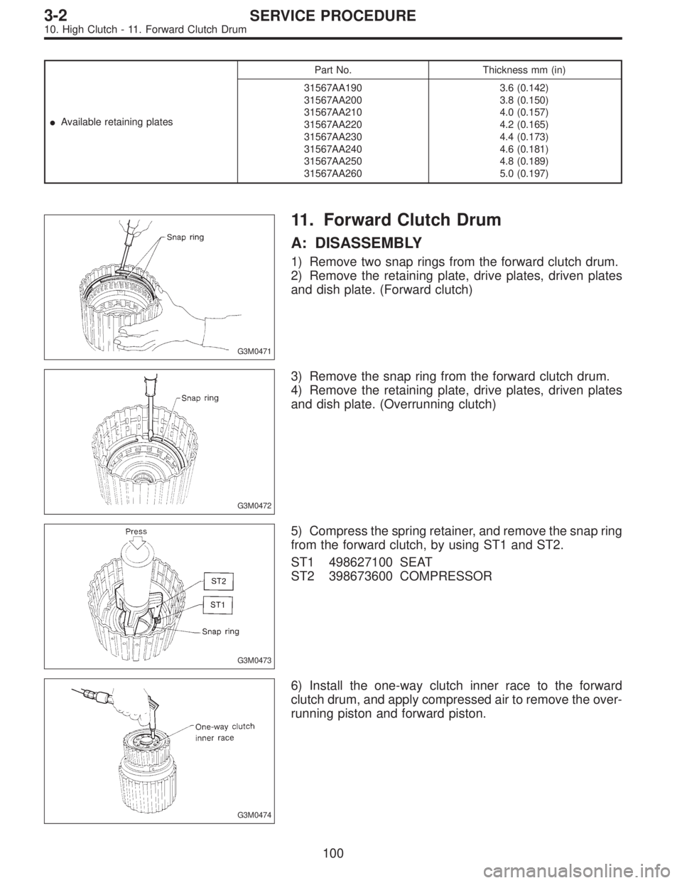
G3M0471
11. Forward Clutch Drum
A: DISASSEMBLY
1) Remove two snap rings from the forward clutch drum.
2) Remove the retaining plate, drive plates, driven plates
and dish plate. (Forward clutch)
G3M0472
3) Remove the snap ring from the forward clutch drum.
4) Remove the retaining plate, drive plates, driven plates
and dish plate. (Overrunning clutch)
G3M0473
5) Compress the spring retainer, and remove the snap ring
from the forward clutch, by using ST1 and ST2.
ST1 498627100 SEAT
ST2 398673600 COMPRESSOR
G3M0474
6) Install the one-way clutch inner race to the forward
clutch drum, and apply compressed air to remove the over-
running piston and forward piston.
100
3-2SERVICE PROCEDURE
10. High Clutch - 11. Forward Clutch Drum
 Straighten the staked portion of the lock nut, and
remove the lock nut while locking the rear spline portion of
the shaft with ST1 and ST2. Then pull of")
 Stake the lock nut securely at two places.
7) Measure dimension“B”of the drive pinion shaft.
8) Determine the thickness t (mm) of the drive pinion shim.
t = 6.5±0.0625 � (B � A)
NOTE:")