Page 2714 of 3342
B4M0915
8N7
CHECK G SENSOR.
1) Remove G sensor from vehicle.
2) Connect connector to G sensor.
3) Connect connector to ABSCM.
4) Turn ignition switch to ON.
5) Measure voltage between G sensor connector termi-
nals.
: Connector & terminal
(P11) No. 2 (+)—No.1(�)
Is voltage 2.3±0.2 V when G sensor is hori-
zontal?
: Go to next.
: Replace G sensor.
B4M0917A
: Connector & terminal
(P11) No. 2 (+)—No.1(�)
Is voltage 3.9±0.2 V when G sensor is
inclined forwards to 90°?
: Go to next.
: Replace G sensor.
B4M0918A
: Connector & terminal
(P11) No. 2 (+)—No.1(�)
Is voltage 0.7±0.2 V when G sensor is
inclined backwards to 90°?
: Go to step8N8.
: Replace G sensor.
8N8CHECK POOR CONTACT IN CONNEC-
TOR BETWEEN ABSCM AND G SENSOR.
: Is there poor contact in connector between
ABSCM and G sensor?
: Repair connector.
: Go to step8N9.
109
4-4cBRAKES [ABS 5.3 TYPE]
8. Diagnostics Chart with Trouble Code
Page 2719 of 3342

1) When a trouble code is not stored in memory, activat-
ing the FE mode causes the initial value to appear on the
select monitor display.
�FE1—4: 159 mile/h
�FE5—8: 255 km/h
�FE13: 16.84 V
�FE14: 5.00 V
�FE15: The MM, B1 and A0 LEDs are on.
The AT and CM LEDs are out.
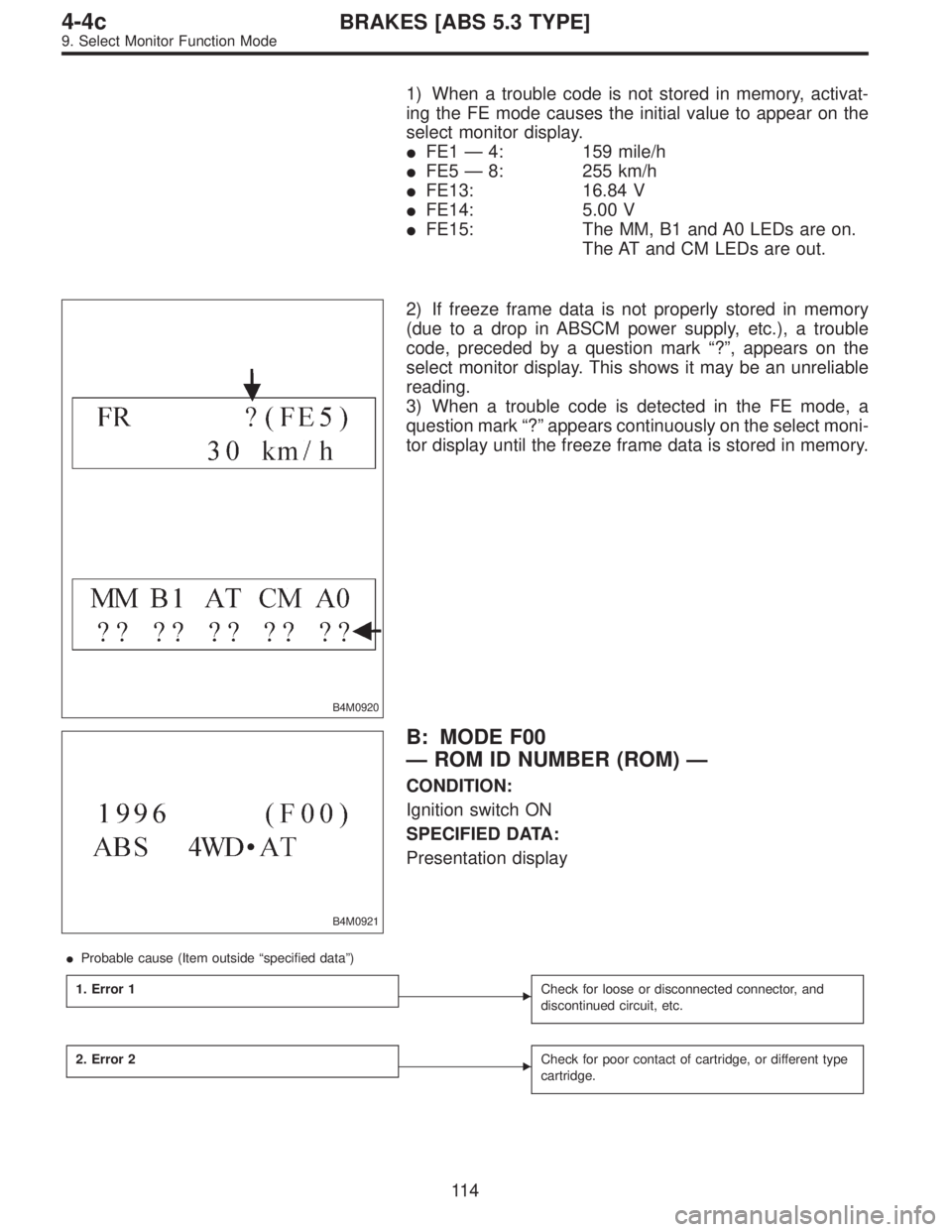
B4M0920
2) If freeze frame data is not properly stored in memory
(due to a drop in ABSCM power supply, etc.), a trouble
code, preceded by a question mark“?”, appears on the
select monitor display. This shows it may be an unreliable
reading.
3) When a trouble code is detected in the FE mode, a
question mark“?”appears continuously on the select moni-
tor display until the freeze frame data is stored in memory.
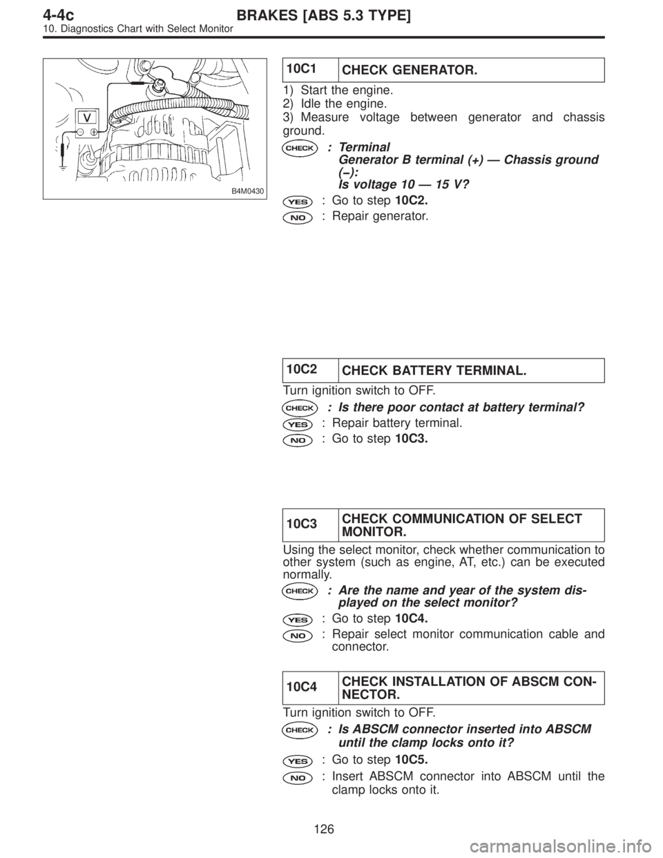
B4M0921
B: MODE F00
—ROM ID NUMBER (ROM)—
CONDITION:
Ignition switch ON
SPECIFIED DATA:
Presentation display
�Probable cause (Item outside“specified data”)
1. Error 1
�Check for loose or disconnected connector, and
discontinued circuit, etc.
2. Error 2�Check for poor contact of cartridge, or different type
cartridge.
11 4
4-4cBRAKES [ABS 5.3 TYPE]
9. Select Monitor Function Mode
Page 2731 of 3342

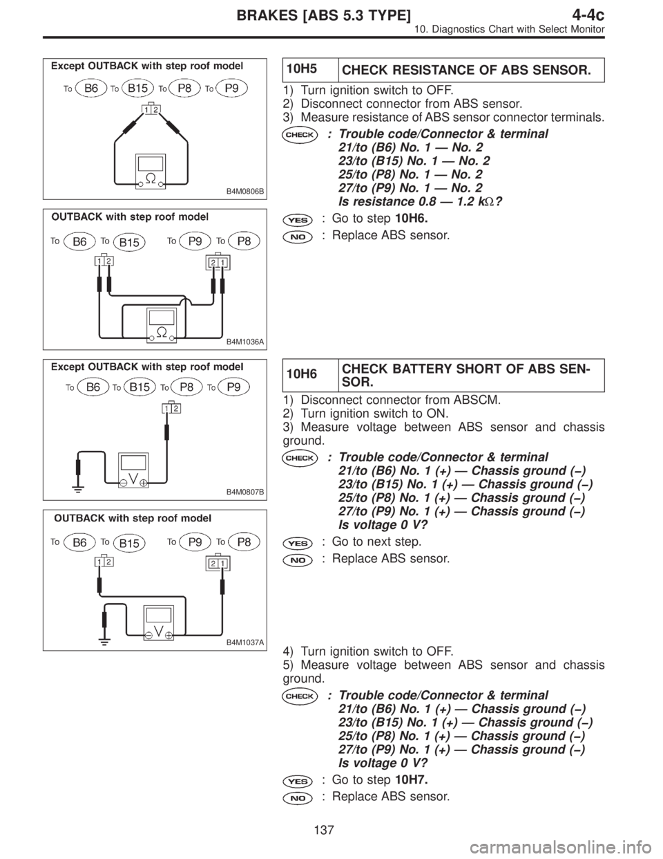
B4M0430
10C1
CHECK GENERATOR.
1) Start the engine.
2) Idle the engine.
3) Measure voltage between generator and chassis
ground.
: Terminal
Generator B terminal (+)—Chassis ground
(�):
Is voltage 10—15 V?
: Go to step10C2.
: Repair generator.
10C2
CHECK BATTERY TERMINAL.
Turn ignition switch to OFF.
: Is there poor contact at battery terminal?
: Repair battery terminal.
: Go to step10C3.
10C3CHECK COMMUNICATION OF SELECT
MONITOR.
Using the select monitor, check whether communication to
other system (such as engine, AT, etc.) can be executed
normally.
: Are the name and year of the system dis-
played on the select monitor?
: Go to step10C4.
: Repair select monitor communication cable and
connector.
10C4CHECK INSTALLATION OF ABSCM CON-
NECTOR.
Turn ignition switch to OFF.
: Is ABSCM connector inserted into ABSCM
until the clamp locks onto it?
: Go to step10C5.
: Insert ABSCM connector into ABSCM until the
clamp locks onto it.
126
4-4cBRAKES [ABS 5.3 TYPE]
10. Diagnostics Chart with Select Monitor
Page 2732 of 3342
B4M0796A
10C5
CHECK POWER SUPPLY OF ABSCM.
1) Disconnect connector from ABSCM.
2) Start engine.
3) Idle the engine.
4) Measure voltage between ABSCM connector and chas-
sis ground.
: Connector & terminal
(F49) No. 28 (+)—Chassis ground (�):
Is voltage 10—15 V?
: Go to step10C6.
: Repair ABSCM power supply circuit.
B4M0797A
10C6
CHECK GROUND CIRCUIT OF ABSCM.
1) Turn ignition switch to OFF.
2) Measure resistance between ABSCM connector and
chassis ground.
: Connector & terminal
(F49) No. 1—Chassis ground:
(F49) No. 55—Chassis ground:
Is resistance less than 0.5Ω?
: Repair harness/connector between ABSCM and
select monitor.
: Go to step10C7.
127
4-4cBRAKES [ABS 5.3 TYPE]
10. Diagnostics Chart with Select Monitor
Page 2733 of 3342
B4M1033B
10C7CHECK HARNESS CONNECTOR
BETWEEN ABSCM AND DATA LINK CON-
NECTOR.
1) Turn ignition switch OFF.
2) Measure resistance between ABSCM connector and
data link connector.
: Connector & terminal
(F49) No. 11—(B78) No. 3
(F49) No. 38—(B78) No. 2
Is resistance less than 0.5Ω?
: Repair harness and connector between ABSCM
and data link connector.
: Go to step10C8.
10C8CHECK POOR CONTACT IN CONNEC-
TOR BETWEEN ABSCM AND DATA LINK
CONNECTOR.
: Is there poor contact in connectors between
ABSCM and data link connector?
: Repair connector.
: Replace ABSCM.
128
4-4cBRAKES [ABS 5.3 TYPE]
10. Diagnostics Chart with Select Monitor
Page 2736 of 3342
10D1
CHECK GROUND SHORT OF HARNESS.
1) Turn ignition switch to OFF.
2) Disconnect connector from ABSCM.
3) Disconnect connector (F50) from relay box.
4) Turn ignition switch to ON.
: Does the ABS warning light remain OFF?
: Go to step10D2.
: Repair harness between ABSCM, relay box ABS
warning light.
10D2CHECK GROUND SHORT OF RELAY
BOX.
1) Turn ignition switch to OFF.
2) Connect connector (F50) to relay box.
3) Disconnect connector (ABS1) from hydraulic unit.
4) Remove valve relay from relay box.
5) Turn ignition switch to ON.
: Does the ABS warning light remain OFF?
: Replace ABSCM.
: Replace relay box.
131
4-4cBRAKES [ABS 5.3 TYPE]
10. Diagnostics Chart with Select Monitor
Page 2742 of 3342

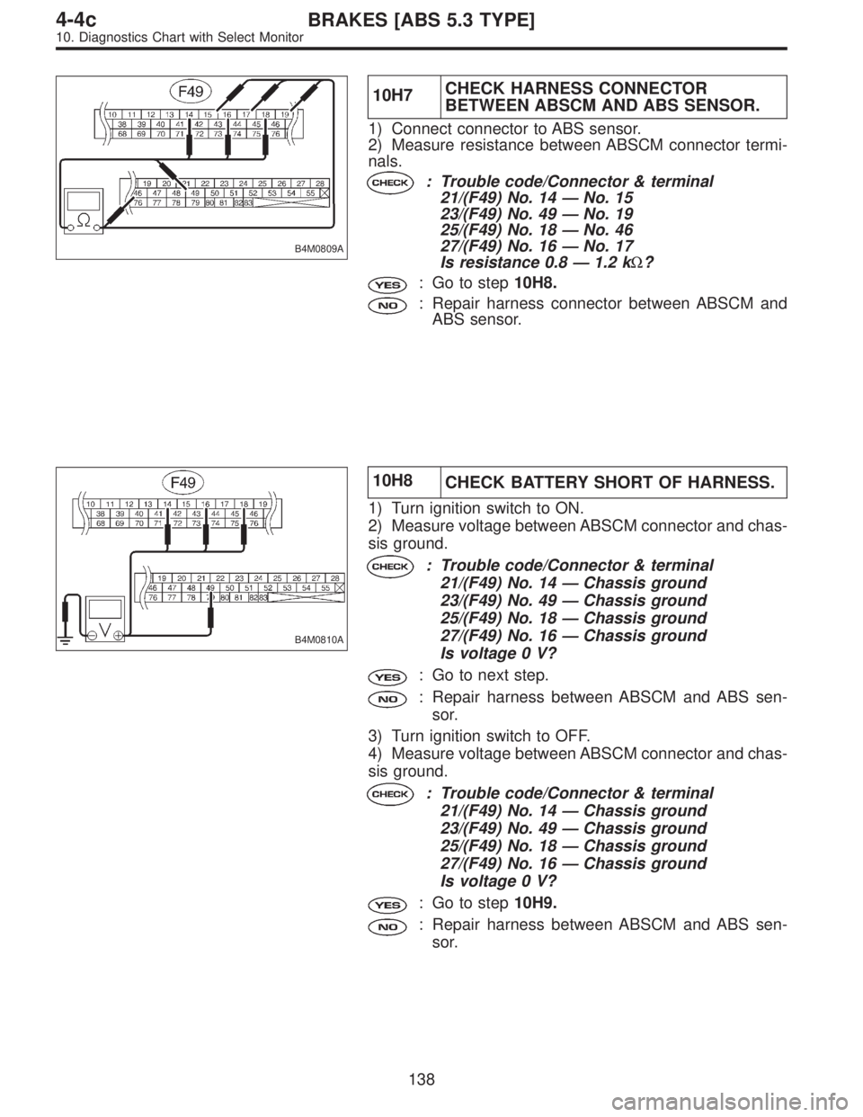
B4M0806B
B4M1036A
10H5
CHECK RESISTANCE OF ABS SENSOR.
1) Turn ignition switch to OFF.
2) Disconnect connector from ABS sensor.
3) Measure resistance of ABS sensor connector terminals.
: Trouble code/Connector & terminal
21/to (B6) No. 1—No. 2
23/to (B15) No. 1—No. 2
25/to (P8) No. 1—No. 2
27/to (P9) No. 1—No. 2
Is resistance 0.8—1.2 kΩ?
: Go to step10H6.
: Replace ABS sensor.
B4M0807B
B4M1037A
10H6CHECK BATTERY SHORT OF ABS SEN-
SOR.
1) Disconnect connector from ABSCM.
2) Turn ignition switch to ON.
3) Measure voltage between ABS sensor and chassis
ground.
: Trouble code/Connector & terminal
21/to (B6) No. 1 (+)—Chassis ground (�)
23/to (B15) No. 1 (+)—Chassis ground (�)
25/to (P8) No. 1 (+)—Chassis ground (�)
27/to (P9) No. 1 (+)—Chassis ground (�)
Is voltage 0 V?
: Go to next step.
: Replace ABS sensor.
4) Turn ignition switch to OFF.
5) Measure voltage between ABS sensor and chassis
ground.
: Trouble code/Connector & terminal
21/to (B6) No. 1 (+)—Chassis ground (�)
23/to (B15) No. 1 (+)—Chassis ground (�)
25/to (P8) No. 1 (+)—Chassis ground (�)
27/to (P9) No. 1 (+)—Chassis ground (�)
Is voltage 0 V?
: Go to step10H7.
: Replace ABS sensor.
137
4-4cBRAKES [ABS 5.3 TYPE]
10. Diagnostics Chart with Select Monitor
Page 2743 of 3342

B4M0809A
10H7CHECK HARNESS CONNECTOR
BETWEEN ABSCM AND ABS SENSOR.
1) Connect connector to ABS sensor.
2) Measure resistance between ABSCM connector termi-
nals.
: Trouble code/Connector & terminal
21/(F49) No. 14—No. 15
23/(F49) No. 49—No. 19
25/(F49) No. 18—No. 46
27/(F49) No. 16—No. 17
Is resistance 0.8—1.2 kΩ?
: Go to step10H8.
: Repair harness connector between ABSCM and
ABS sensor.
B4M0810A
10H8
CHECK BATTERY SHORT OF HARNESS.
1) Turn ignition switch to ON.
2) Measure voltage between ABSCM connector and chas-
sis ground.
: Trouble code/Connector & terminal
21/(F49) No. 14—Chassis ground
23/(F49) No. 49—Chassis ground
25/(F49) No. 18—Chassis ground
27/(F49) No. 16—Chassis ground
Is voltage 0 V?
: Go to next step.
: Repair harness between ABSCM and ABS sen-
sor.
3) Turn ignition switch to OFF.
4) Measure voltage between ABSCM connector and chas-
sis ground.
: Trouble code/Connector & terminal
21/(F49) No. 14—Chassis ground
23/(F49) No. 49—Chassis ground
25/(F49) No. 18—Chassis ground
27/(F49) No. 16—Chassis ground
Is voltage 0 V?
: Go to step10H9.
: Repair harness between ABSCM and ABS sen-
sor.
138
4-4cBRAKES [ABS 5.3 TYPE]
10. Diagnostics Chart with Select Monitor