Page 2664 of 3342
G: TROUBLE CODE 41
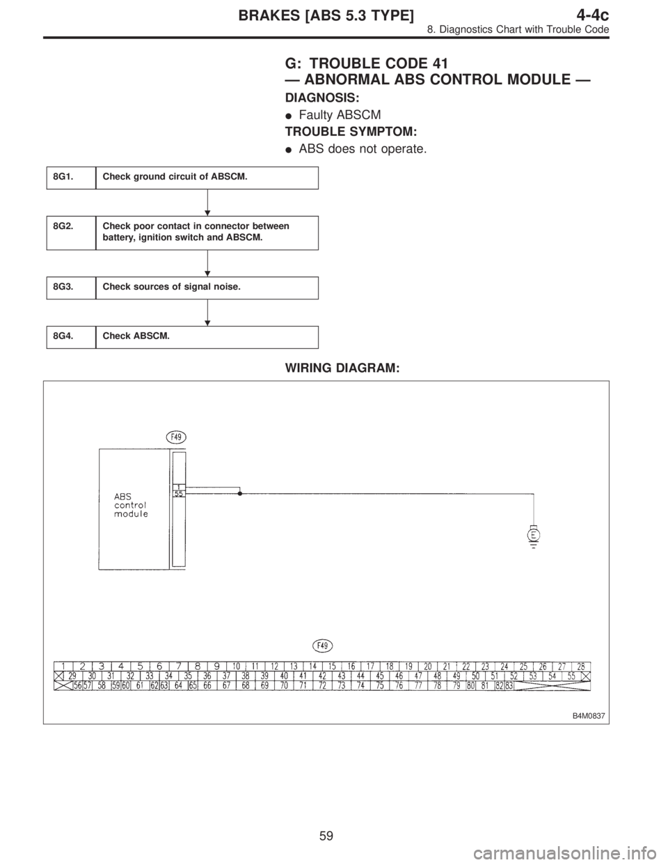
—ABNORMAL ABS CONTROL MODULE—
DIAGNOSIS:
�Faulty ABSCM
TROUBLE SYMPTOM:
�ABS does not operate.
8G1.Check ground circuit of ABSCM.
8G2.Check poor contact in connector between
battery, ignition switch and ABSCM.
8G3.Check sources of signal noise.
8G4.Check ABSCM.
WIRING DIAGRAM:
B4M0837
�
�
�
59
4-4cBRAKES [ABS 5.3 TYPE]
8. Diagnostics Chart with Trouble Code
Page 2665 of 3342
B4M0838A
8G1
CHECK GROUND CIRCUIT OF ABSCM.
1) Turn ignition switch to OFF.
2) Disconnect connector from ABSCM.
3) Measure resistance between ABSCM and chassis
ground.
: Connector & terminal
(F49) No. 1—Chassis ground
(F49) No. 55—Chassis ground
Is resistance less than 0.5Ω?
: Go to step8G2.
: Repair ABSCM ground harness.
8G2CHECK POOR CONTACT IN CONNEC-
TORS BETWEEN BATTERY, IGNITION
SWITCH AND ABSCM.
: Is there poor contact in connectors between
battery, ignition switch and ABSCM?
: Repair connector.
: Go to step8G3.
8G3
CHECK SOURCES OF SIGNAL NOISE.
: Is the car telephone or the wireless trans-
mitter properly installed?
: Go to next.
: Properly install the car telephone or the wireless
transmitter.
: Are noise sources (such as an antenna)
installed near the sensor harness?
: Install the noise sources apart from the sensor
harness.
: Go to step8G4.
60
4-4cBRAKES [ABS 5.3 TYPE]
8. Diagnostics Chart with Trouble Code
Page 2669 of 3342
B4M0430
8H1
CHECK GENERATOR.
1) Start engine.
2) Idling after warm-up.
3) Measure voltage between generator B terminal and
chassis ground.
: Terminal
Generator B terminal—Chassis ground
Is voltage 10—15 V?
: Go to step8H2.
: Repair generator.
8H2
CHECK BATTERY TERMINAL.
Turn ignition switch to OFF.
: Are the positive and negative battery termi-
nals tightly clamped?
: Go to step8H3.
: Tighten the clamp of terminal.
B4M0842A
8H3
CHECK INPUT VOLTAGE OF ABSCM.
1) Disconnect connector from ABSCM.
2) Run the engine at idle.
3) Measure voltage between ABSCM connector and chas-
sis ground.
: Connector & terminal
(F49) No. 28 (+)—Chassis ground (�)
Is voltage 10—15 V?
: Go to step8H4.
: Repair harness connector between battery, igni-
tion switch and ABSCM.
64
4-4cBRAKES [ABS 5.3 TYPE]
8. Diagnostics Chart with Trouble Code
Page 2670 of 3342
B4M0843A
8H4
CHECK GROUND CIRCUIT OF ABSCM.
1) Turn ignition switch to OFF.
2) Measure resistance between ABSCM connector and
chassis ground.
: Connector & terminal
(F49) No. 1—Chassis ground
Is resistance less than 0.5Ω?
: Go to step8H5.
: Repair ABSCM ground harness.
8H5CHECK POOR CONTACT IN CONNEC-
TOR BETWEEN GENERATOR, BATTERY
AND ABSCM.
: Is there poor contact in connectors between
generator, battery and ABSCM?
: Repair connector.
: Go to step8H6.
8H6
CHECK ABSCM.
1) Connect all connectors.
2) Erase the memory.
3) Perform inspection mode.
4) Read out the trouble code.
: Is the same trouble code as in the current
diagnosis still being output?
: Replace ABSCM.
: Go to next.
: Are other trouble codes being output?
: Proceed with the diagnosis corresponding to the
trouble code.
: A temporary poor contact.
65
4-4cBRAKES [ABS 5.3 TYPE]
8. Diagnostics Chart with Trouble Code
Page 2673 of 3342
B4M0846A
8I2
CHECK GROUND SHORT OF HARNESS.
1) Turn ignition switch to OFF.
2) Disconnect two connectors from AT control module.
3) Disconnect connector from ABSCM.
4) Measure resistance between ABSCM connector and
chassis ground.
: Connector & terminal
(F49) No. 12—Chassis ground
Is resistance more than 1 MΩ?
: Go to step8I3.
: Repair harness between AT control module and
ABSCM.
B4M0847A
8I3
CHECK BATTERY SHORT OF HARNESS.
1) Turn ignition switch to ON.
2) Measure voltage between ABSCM connector and chas-
sis ground.
: Connector & terminal
(F49) No. 12 (+)—Chassis ground (�)
Is voltage 0 V?
: Go to next step.
: Repair harness between AT control module and
ABSCM.
3) Turn ignition switch to OFF.
4) Measure voltage between ABSCM connector and chas-
sis ground.
: Connector & terminal
(F49) No. 12 (+)—Chassis ground (�)
Is voltage 0 V?
: Go to step8I4.
: Repair harness between AT control module and
ABSCM.
68
4-4cBRAKES [ABS 5.3 TYPE]
8. Diagnostics Chart with Trouble Code
Page 2674 of 3342
B4M0848B
8I4
CHECK AT CONTROL MODULE.
1) Connect all connectors to AT control module.
2) Turn ignition switch to ON.
3) Measure voltage between AT control module connector
terminals.
: Connector & terminal
(B55) No. 1 (+)—(B56) No. 5 (�)
Is voltage 10—13 V?
: Go to step8I5.
: Go to next step.
B4M0849B
4) Measure voltage between AT control module connector
and chassis ground.
: Connector & terminal
(B54) No. 6 (+)—Chassis ground (�)
(B55) No. 1 (+)—Chassis ground (�)
Is voltage 10—13 V?
: Replace AT control module.
: Repair harness connector between battery, igni-
tion switch and AT control module.
B4M0844A
8I5
CHECK OPEN CIRCUIT OF HARNESS.
Measure voltage between ABSCM connector and chassis
ground.
: Connector & terminal
(F49) No. 12 (+)—Chassis ground (�)
(F49) No. 39 (+)—Chassis ground (�)
Is voltage 10—13 V?
: Go to step8I6.
: Repair harness connector between AT control
module and ABSCM.
69
4-4cBRAKES [ABS 5.3 TYPE]
8. Diagnostics Chart with Trouble Code
Page 2677 of 3342
WIRING DIAGRAM:
B4M1047
B4M0851B
8J1
CHECK G SENSOR.
1) Turn ignition switch to OFF.
2) Remove console box.
3) Disconnect connector from G sensor.
4) Measure resistance of G sensor.
: Connector & terminal
To (P11) No. 1—No. 3
Is resistance 50±8 kΩ?
: Go to step8J2.
: Replace G sensor.
72
4-4cBRAKES [ABS 5.3 TYPE]
8. Diagnostics Chart with Trouble Code
Page 2679 of 3342
 Turn ignition switch to ON.
2) Measure voltage between ABSCM connector and chas-
sis ground.
: Connector & terminal
(F49) No. 8 (+)—Chassis ground (�)")
B4M0855A
8J5
CHECK BATTERY SHORT OF HARNESS.
1) Turn ignition switch to ON.
2) Measure voltage between ABSCM connector and chas-
sis ground.
: Connector & terminal
(F49) No. 8 (+)—Chassis ground (�)
(F49) No. 45 (+)—Chassis ground (�)
Is voltage 0 V?
: Go to next step.
: Repair harness between ABSCM and G sensor.
3) Turn ignition switch to OFF.
4) Measure voltage between ABSCM and chassis ground.
: Connector & terminal
(F49) No. 8 (+)—Chassis ground (�)
(F49) No. 45 (+)—Chassis ground (�)
Is voltage 0 V?
: Go to step8J6.
: Repair harness between ABSCM and chassis
ground.
8J6CHECK POOR CONTACT IN CONNEC-
TOR BETWEEN ABSCM AND G SENSOR.
: Is there poor contact in connectors between
ABSCM and G sensor?
: Repair connector.
: Go to step8J7.
8J7
CHECK ABSCM.
1) Connect all connectors.
2) Erase the memory.
3) Perform inspection mode.
4) Read out the trouble code.
: Is the same trouble code as in the current
diagnosis still being output?
: Replace ABSCM.
: Go to next.
: Are other trouble codes being output?
: Proceed with the diagnosis corresponding to the
trouble code.
: A temporary poor contact.
74
4-4cBRAKES [ABS 5.3 TYPE]
8. Diagnostics Chart with Trouble Code
 Turn ignition switch to OFF.
2) Disconnect connector from ABSCM.
3) Measure resistance between ABSCM and chassis
ground.
: Connector & terminal
(F49) No.")
 Start engine.
2) Idling after warm-up.
3) Measure voltage between generator B terminal and
chassis ground.
: Terminal
Generator B terminal—Chassis ground
Is voltage 1")
 Turn ignition switch to OFF.
2) Measure resistance between ABSCM connector and
chassis ground.
: Connector & terminal
(F49) No. 1—Chassis ground
Is res")
 Turn ignition switch to OFF.
2) Disconnect two connectors from AT control module.
3) Disconnect connector from ABSCM.
4) Measure resistance between ABSCM")
 Connect all connectors to AT control module.
2) Turn ignition switch to ON.
3) Measure voltage between AT control module connector
terminals.
: Connector & ter")
 Turn ignition switch to OFF.
2) Remove console box.
3) Disconnect connector from G sensor.
4) Measure resistance of G sensor.
: Connector & term")