Page 271 of 3342
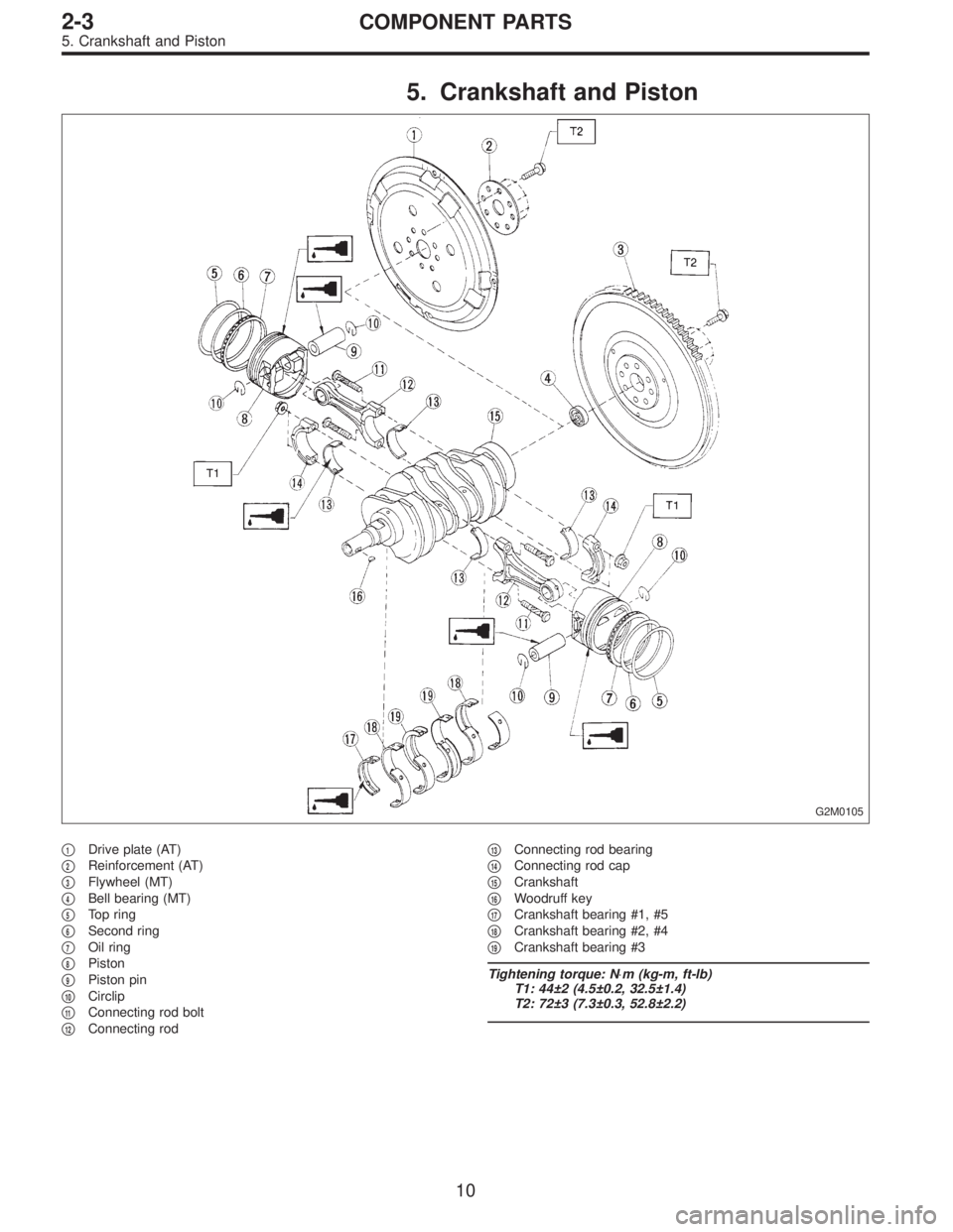
5. Crankshaft and Piston
G2M0105
�1Drive plate (AT)
�
2Reinforcement (AT)
�
3Flywheel (MT)
�
4Bell bearing (MT)
�
5Top ring
�
6Second ring
�
7Oil ring
�
8Piston
�
9Piston pin
�
10Circlip
�
11Connecting rod bolt
�
12Connecting rod�
13Connecting rod bearing
�
14Connecting rod cap
�
15Crankshaft
�
16Woodruff key
�
17Crankshaft bearing #1, #5
�
18Crankshaft bearing #2, #4
�
19Crankshaft bearing #3
Tightening torque: N⋅m (kg-m, ft-lb)
T1: 44±2 (4.5±0.2, 32.5±1.4)
T2: 72±3 (7.3±0.3, 52.8±2.2)
10
2-3COMPONENT PARTS
5. Crankshaft and Piston
Page 276 of 3342
 Fill rocker arm’s oil reservoir with engine oil and install
lash adjuster.
CAUTION:
�Do not rotate lash adjuster during installation.
�Be careful not to scratch the oil seal.
B2M0414
CAUTION:
Whe")
6) Fill rocker arm’s oil reservoir with engine oil and install
lash adjuster.
CAUTION:
�Do not rotate lash adjuster during installation.
�Be careful not to scratch the oil seal.
B2M0414
CAUTION:
When removing valve rocker assembly, keep the
assembly soaked in engine oil, or position it with air
bleeding orifice on rocker arm facing upward as
shown. This prevents oil leakage from and air entering
into the hydraulic lash adjuster. Failure to do so may
cause air to enter the hydraulic lash adjuster, causing
loss in performance.
B2M0382B
7) Temporarily and equally tighten bolts�1through�4.Do
not allow knock pin to catch valve rocker assembly.
8) Tighten bolts�
5through�8to specified torque.
9) Tighten bolts�
1through�4to specified torque.
Tightening torque:
12±1 N⋅m (1.2±0.1 kg-m, 8.7±0.7 ft-lb)
10) Install rocker covers.
Tightening torque:
5±1 N⋅m (0.5±0.1 kg-m, 3.6±0.7 ft-lb)
11) Connect harness connectors, hoses, etc. to their posi-
tions.
14
2-3SERVICE PROCEDURE
2. Hydraulic Lash Adjuster
Page 284 of 3342
C: INSTALLATION
1. SPROCKET
B2M0416B
Tightening torque: N⋅m (kg-m, ft-lb)
T1: 5±1 (0.5±0.1, 3.6±0.7)
T2: 25±2 (2.5±0.2, 18.1±1.4)
T3: 78±5 (8.0±0.5, 57.9±3.6)
G2M0114
1) Install right side belt cover No. 2.
2) Install tensioner bracket.
3) Install left side belt cover No. 2.
4) Install crankshaft sprocket.
5) Install right side camshaft sprocket and left side cam-
shaft sprocket. To lock camshaft use ST.
ST 499207100 CAMSHAFT SPROCKET WRENCH
CAUTION:
Do not confuse left and right side camshaft sprockets
during installation. The left side camshaft sprocket is
identified by a projection used to monitor cam angle
sensor.
22
2-3SERVICE PROCEDURE
3. Timing Belt
Page 285 of 3342
2. BELT TENSIONER AND IDLER
B2M0070A
Tightening torque: N⋅m (kg-m, ft-lb)
T: 39±4 (4.0±0.4, 28.9±2.9)
B2M0109A
1) Installation of belt tension adjuster
Insert stopper pin 1.5 mm (0.059 in) diameter into place
while pushing tension adjuster rod into body using a press.
CAUTION:
�Do not allow press pressure to exceed 9,807 N (1,000
kg, 2,205 lb).
�Do not release press pressure until stopper pin is
completely inserted.
�Push tension adjuster rod vertically.
�Press-in the push rod gradually taking three minutes
or more.
23
2-3SERVICE PROCEDURE
3. Timing Belt
Page 286 of 3342
2) Install belt tensioner and spacer.
3) Install belt idler.
B2M0110
4) Temporarily tighten bolts while belt tension adjuster is
pushed all the way to the right.
3. TIMING BELT
B2M0071A
Tightening torque: N⋅m (kg-m, ft-lb)
T1: 25±2 (2.5±0.2, 18.1±1.4)
T2: 39±4 (4.0±0.4, 28.9±2.9)
24
2-3SERVICE PROCEDURE
3. Timing Belt
Page 288 of 3342
4. CRANKSHAFT PULLEY AND BELT COVER
G2M0126
Tightening torque: N⋅m (kg-m, ft-lb)
T1: 5±1 (0.5±0.1, 3.6±0.7)
T2: 127±10 (13.0±1.0, 94±7)
1) Install front belt cover.
2) Install right side belt cover.
3) Install left side belt cover.
4) Install crankshaft pulley.
G2M0108
5) Install pulley bolt.
To lock crankshaft, use ST.
ST 499977000 CRANKSHAFT PULLEY WRENCH
6) Install V-belt.
26
2-3SERVICE PROCEDURE
3. Timing Belt
Page 293 of 3342
D: ASSEMBLY
B2M1264B
Tightening torque: N⋅m (kg-m, ft-lb)
T: 5±1 (0.5±0.1, 3.6±0.7)
1) Install rocker adjust screw and nut to rocker arm, and
loosely tighten nut.
2) Arrange valve rocker arms, springs and shaft supports
in assembly order and insert valve rocker shaft. Ensure
that cutout portion of rocker shaft faces oil holes�
Ain shaft
supports.
CAUTION:
Valve rocker arms, rocker shaft and shaft supports
have identification marks. Ensure parts with same
markings are properly assembled.
3) Install valve rocker shaft securing bolts while aligning
shaft“lock”holes�
Bwith bolts.
31
2-3SERVICE PROCEDURE
4. Valve Rocker Assembly
Page 294 of 3342
E: INSTALLATION
B2M1206B
Tightening torque: N⋅m (kg-m, ft-lb)
T1: 5±1 (0.5±0.1, 3.6±0.7)
T2: 12±1 (1.2±0.1, 8.7±0.7)
B2M1207B
1) Installation of valve rocker assembly
(1) Temporarily tighten bolts�
1through�4equally as
shown in Figure.
CAUTION:
Do not allow valve rocker assembly to gouge knock
pins.
(2) Tighten bolts�
5through�8to specified torque.
(3) Tighten bolts�
1through�4to specified torque.
2) Adjust the valve clearances.
3) Install rocker cover and connect PCV hose.
32
2-3SERVICE PROCEDURE
4. Valve Rocker Assembly

T1: 5±1 (0.5±0.1, 3.6±0.7)
T2: 25±2 (2.5±0.2, 18.1±1.4)
T3: 78±5 (8.0±0.5, 57.9±3.6)
G2M0114
1) Install right side")

T: 39±4 (4.0±0.4, 28.9±2.9)
B2M0109A
1) Installation of belt tension adjuster
Insert stopper pin 1.5 mm (0.059 in) diamet")
 Install belt tensioner and spacer.
3) Install belt idler.
B2M0110
4) Temporarily tighten bolts while belt tension adjuster is
pushed all the way to the right.
3. TIMING BELT
B2M0071A
Tightening tor")

T1: 5±1 (0.5±0.1, 3.6±0.7)
T2: 127±10 (13.0±1.0, 94±7)
1) Install front belt cover.
2) Install right side belt")

T: 5±1 (0.5±0.1, 3.6±0.7)
1) Install rocker adjust screw and nut to rocker arm, and
loosely tighten nut.
2) Arrange valve rocker arms, sp")

T1: 5±1 (0.5±0.1, 3.6±0.7)
T2: 12±1 (1.2±0.1, 8.7±0.7)
B2M1207B
1) Installation of valve rocker assembly
(1) Temporarily tighten b")