Page 361 of 3342
5. SPROCKET
1) Check sprocket teeth for abnormal wear and scratches.
2) Make sure there is no free play between sprocket and
key.
3) Check crankshaft sprocket notch for sensor for damage
and contamination of foreign matter.
C: INSTALLATION
1. SPROCKET
B2M0691B
Tightening torque: N⋅m (kg-m, ft-lb)
T1: 4.9±0.5 (0.5±0.05, 3.6±0.4)
T2: 25±2 (2.5±0.2, 18±1.4)
T3: 78±5 (8.0±0.5, 58±3.6)
B2M0738
1) Install right-hand belt cover No. 2.
20
2-3bSERVICE PROCEDURE
2. Timing Belt
Page 363 of 3342
2. BELT TENSIONER AND IDLER
B2M0690B
Tightening torque: N⋅m (kg-m, ft-lb)
T1: 25±2 (2.5±0.2, 18±1.4)
T2: 39±4 (4.0±0.4, 29±2.9)
G2M0119
1) Installation of belt tensioner adjuster
(1) Insert stopper pin 1.5 mm (0.059 in) dia. into place
while pushing tension adjuster rod into body using a
press.
CAUTION:
�Do not allow press pressure to exceed 9,807 N (1,000
kg, 2,205 lb).
�Do not release press pressure until stopper pin is
completely inserted.
�Push tension adjuster rod vertically.
�Press-in the push rod gradually, taking three min-
utes or more.
22
2-3bSERVICE PROCEDURE
2. Timing Belt
Page 364 of 3342
G2M0725
(2) Temporarily tighten bolts while tension adjuster is
pushed all the way to the right.
G2M0726
2) Install belt tensioner.
3) Install belt idler.
4) Install belt idler No. 2.
3. TIMING BELT
B2M0693A
Tightening torque: N⋅m (kg-m, ft-lb)
T: 39±4 (4.0±0.4, 29±2.9)
23
2-3bSERVICE PROCEDURE
2. Timing Belt
Page 369 of 3342
4. CRANKSHAFT PULLEY AND BELT COVER
B2M1215B
Tightening torque: N⋅m (kg-m, ft-lb)
T1: 5±0.5 (0.5±0.05, 3.6±0.4)
T2: 177±10 (18.0±1.0, 130±7)
B2M0731
1) Install front belt cover.
B2M0730
2) Install right-hand belt cover.
B2M0729
3) Install left-hand belt cover.
4) Install crankshaft pulley.
28
2-3bSERVICE PROCEDURE
2. Timing Belt
Page 374 of 3342
C: INSTALLATION
1. CAMSHAFT
B2M1304F
Tightening torque: N⋅m (kg-m, ft-lb)
T1: 5±0.5 (0.5±0.05, 3.6±0.4)
T2: 10±0.7 (1.0±0.07, 7.2±0.5)
T3: 20±2 (2.0±0.2, 14.5±1.4)
B2M1200A
1) Camshaft installation
Apply engine oil to cylinder head at camshaft bearing loca-
tion before installing camshaft. Install camshaft so that
rocker arm is close to or in contact with“base circle”of cam
lobe.
CAUTION:
�When camshafts are positioned as shown in figure,
camshafts need to be rotated at a minimum to align
with timing belt during installation.
�Right-hand camshaft need not be rotated when set
at position shown in figure.
Left-hand intake camshaft: Rotate 80°clockwise.
Left-hand exhaust camshaft: Rotate 45°counter-clock-
wise.
33
2-3bSERVICE PROCEDURE
3. Camshaft
Page 375 of 3342

G2M0752
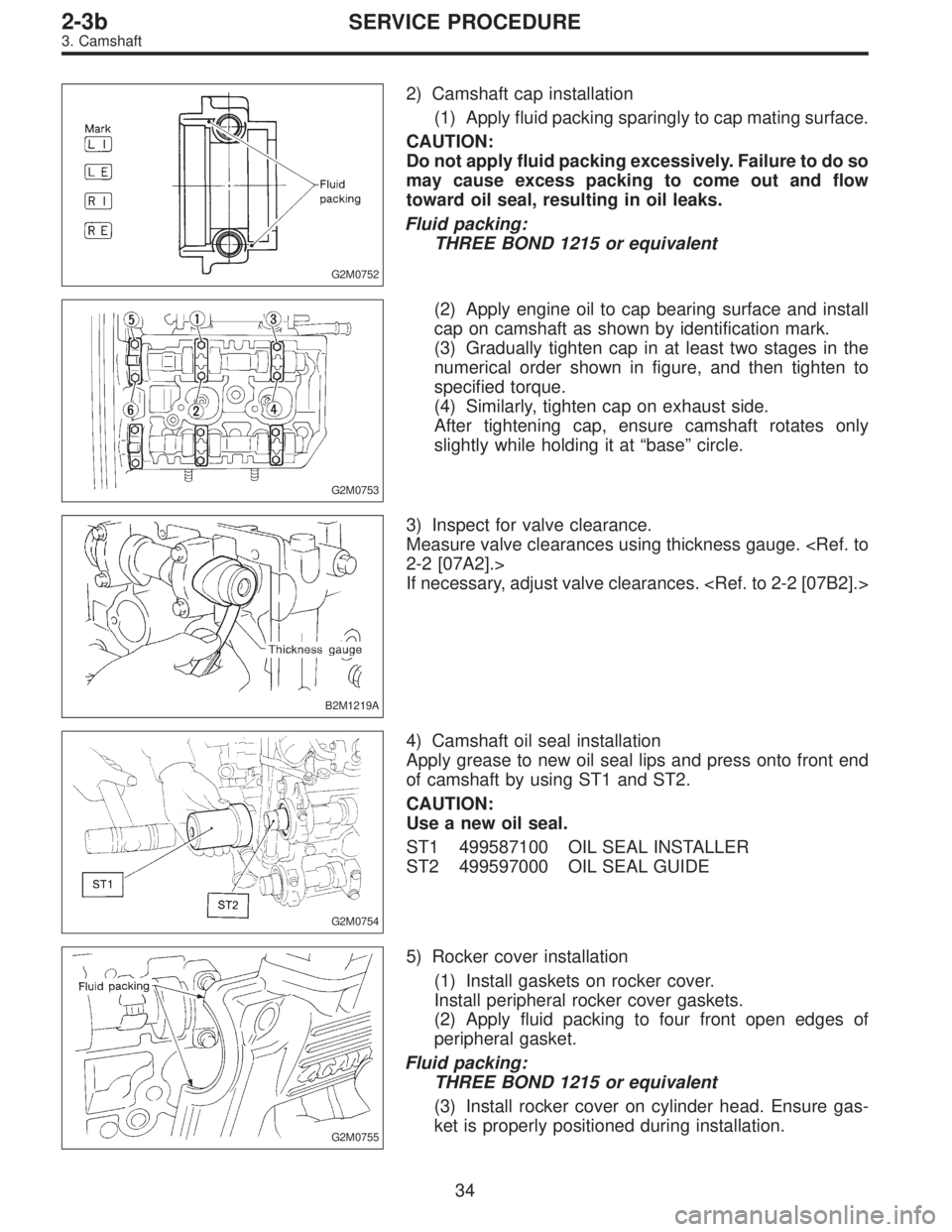
2) Camshaft cap installation
(1) Apply fluid packing sparingly to cap mating surface.
CAUTION:
Do not apply fluid packing excessively. Failure to do so
may cause excess packing to come out and flow
toward oil seal, resulting in oil leaks.
Fluid packing:
THREE BOND 1215 or equivalent
G2M0753
(2) Apply engine oil to cap bearing surface and install
cap on camshaft as shown by identification mark.
(3) Gradually tighten cap in at least two stages in the
numerical order shown in figure, and then tighten to
specified torque.
(4) Similarly, tighten cap on exhaust side.
After tightening cap, ensure camshaft rotates only
slightly while holding it at“base”circle.
B2M1219A
3) Inspect for valve clearance.
Measure valve clearances using thickness gauge.
2-2 [07A2].>
If necessary, adjust valve clearances.
G2M0754
4) Camshaft oil seal installation
Apply grease to new oil seal lips and press onto front end
of camshaft by using ST1 and ST2.
CAUTION:
Use a new oil seal.
ST1 499587100 OIL SEAL INSTALLER
ST2 499597000 OIL SEAL GUIDE
G2M0755
5) Rocker cover installation
(1) Install gaskets on rocker cover.
Install peripheral rocker cover gaskets.
(2) Apply fluid packing to four front open edges of
peripheral gasket.
Fluid packing:
THREE BOND 1215 or equivalent
(3) Install rocker cover on cylinder head. Ensure gas-
ket is properly positioned during installation.
34
2-3bSERVICE PROCEDURE
3. Camshaft
Page 379 of 3342

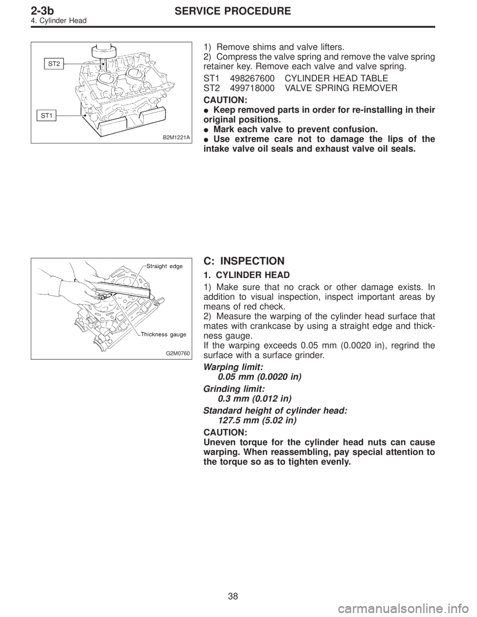
B2M1221A
1) Remove shims and valve lifters.
2) Compress the valve spring and remove the valve spring
retainer key. Remove each valve and valve spring.
ST1 498267600 CYLINDER HEAD TABLE
ST2 499718000 VALVE SPRING REMOVER
CAUTION:
�Keep removed parts in order for re-installing in their
original positions.
�Mark each valve to prevent confusion.
�Use extreme care not to damage the lips of the
intake valve oil seals and exhaust valve oil seals.
G2M0760
C: INSPECTION
1. CYLINDER HEAD
1) Make sure that no crack or other damage exists. In
addition to visual inspection, inspect important areas by
means of red check.
2) Measure the warping of the cylinder head surface that
mates with crankcase by using a straight edge and thick-
ness gauge.
If the warping exceeds 0.05 mm (0.0020 in), regrind the
surface with a surface grinder.
Warping limit:
0.05 mm (0.0020 in)
Grinding limit:
0.3 mm (0.012 in)
Standard height of cylinder head:
127.5 mm (5.02 in)
CAUTION:
Uneven torque for the cylinder head nuts can cause
warping. When reassembling, pay special attention to
the torque so as to tighten evenly.
38
2-3bSERVICE PROCEDURE
4. Cylinder Head
Page 387 of 3342
(7) Further tighten all bolts by 80 to 90°in numerical
sequence.
CAUTION:
Ensure that the total“re-tightening angle”[steps (6)
and (7) above] do not exceed 180°.
3) Install oil level gauge guide attaching bolt (left side
only).
2. INTAKE MANIFOLD
1) Install camshafts, rocker cover and related parts.
G2M0750
Tightening torque: N⋅m (kg-m, ft-lb)
T1: 10±0.7 (1.0±0.07, 7.2±0.5)
T2: 20±2 (2.0±0.2, 14.5±1.4)
46
2-3bSERVICE PROCEDURE
4. Cylinder Head