Page 471 of 3342

�1Intake manifold gasket LH
�
2Intake manifold gasket RH
�
3Fuel injector pipe insulator
�
4Fuel injector pipe
�
5O-ring A
�
6O-ring B
�
7Fuel injector
�
8Insulator
�
9Fuel injector cap
�
10Plate
�
11Sealing
�
12Gasket
�
13Engine coolant hose B
�
14Air by-pass hose
�
15Idle air control solenoid valve
�
16Engine coolant hose A
�
17Nipple (AT model)
�
18Plug
�
19PCV valve
�
20Purge control solenoid valve
�
21Nipple
�
22BPT (Except 2200 cc MT model)
�
23BPT holder bracket (Except 2200 cc MT model)
�
24Back pressure hose (Except 2200 cc MT model)
�
25EGR vacuum hose A (Except 2200 cc MT model)�
26EGR vacuum hose B (Except 2200 cc MT model)
�
27EGR valve (Except 2200 cc MT model)
�
28Gasket (Except 2200 cc MT model)
�
29EGR solenoid valve (Except 2200 cc MT model)
�
30EGR pipe (Except 2200 cc MT model)
�
31Pressure sensor
�
32Pressure sources switching solenoid valve
�
33Vacuum hose A
�
34Vacuum hose B
�
35Vacuum hose C
�
36Bracket (Except Canada spec. vehicles)
�
37Bracket (For Canada spec. vehicles)
�
38Intake manifold
Tightening torque: N⋅m (kg-m, ft-lb)
T1: 3.4±0.5 (0.35±0.05, 2.5±0.4)
T2: 4.9±0.5 (0.5±0.05, 3.6±0.4)
T3: 6.4±0.5 (0.65±0.05, 4.7±0.4)
T4: 16±1.5 (1.6±0.15, 11.6±1.1)
T5: 19±1.5 (1.9±0.15, 13.7±1.1)
T6: 19±2 (1.9±0.2, 13.7±1.4)
T7: 23±3 (2.3±0.3, 16.6±2.2)
T8: 25±2 (2.5±0.2, 18.1±1.4)
T9: 34±2 (3.5±0.2, 25.3±1.4)
3
2-7COMPONENT PARTS
1. Intake Manifold
Page 472 of 3342

2. 2500 cc MODEL
B2M1198A
�1Intake manifold gasket LH
�
2Intake manifold gasket RH
�
3Fuel injector pipe insulator
�
4Fuel injector pipe
�
5O-ring A
�
6O-ring B
�
7Fuel injector
�
8Insulator
�
9Fuel injector cap
�
10Plate
�
11Sealing
�
12Gasket
�
13Engine coolant hose B
�
14Air by-pass hose
�
15Idle air control solenoid valve
�
16Engine coolant hose A
�
17Nipple (AT model)
�
18Plug
�
19PCV valve�
20Purge control solenoid valve
�
21Nipple
�
22BPT
�
23BPT holder bracket
�
24Back pressure hose
�
25EGR vacuum hose A
�
26EGR vacuum pipe
�
27EGR vacuum hose C
�
28EGR valve
�
29Gasket
�
30EGR vacuum hose B
�
31EGR solenoid valve
�
32EGR pipe
�
33Pressure sensor
�
34Pressure sources switching solenoid
valve
�
35Vacuum hose A
�
36Vacuum hose B
�
37Vacuum hose C�
38Bracket
(Except Canada spec. vehicles)
�
39Bracket
(For Canada spec. vehicles)
�
40Collar
�
41Intake manifold
Tightening torque: N⋅m (kg-m, ft-lb)
T1: 3.4±0.5 (0.35±0.05, 2.5±0.4)
T2: 4.9±0.5 (0.5±0.05, 3.6±0.4)
T3: 6.4±0.5 (0.65±0.05, 4.7±0.4)
T4: 16±1.5 (1.6±0.15, 11.6±1.1)
T5: 19±1.5 (1.9±0.15, 13.7±1.1)
T6: 19±2 (1.9±0.2, 13.7±1.4)
T7: 23±3 (2.3±0.3, 16.6±2.2)
T8: 25±2 (2.5±0.2, 18.1±1.4)
T9: 34±2 (3.5±0.2, 25.3±1.4)
4
2-7COMPONENT PARTS
1. Intake Manifold
Page 477 of 3342
B2M1214A
3. Throttle Body
A: REMOVAL AND INSTALLATION
1) Loosen clamps which connect air intake duct to air
intake chamber and mass air flow sensor.
2) Disconnect blow-by hose from air intake duct.
3) Remove air intake duct.
B2M1218
4) Loosen clamp which connects air intake chamber to
throttle body.
5) Disconnect air hoses, and remove air intake chamber.
G2M0280
6) Disconnect accelerator cable�1.
7) Disconnect cruise control cable�
2. (With cruise control
model)
B2M1247
8) Disconnect connector from throttle position sensor.
B2M1248
9) Disconnect engine coolant hoses from throttle body.
9
2-7SERVICE PROCEDURE
3. Throttle Body
Page 482 of 3342
B2M1241
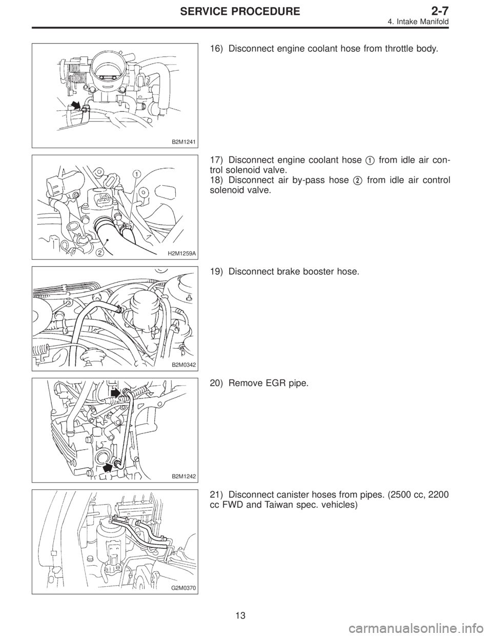
16) Disconnect engine coolant hose from throttle body.
H2M1259A
17) Disconnect engine coolant hose�1from idle air con-
trol solenoid valve.
18) Disconnect air by-pass hose�
2from idle air control
solenoid valve.
B2M0342
19) Disconnect brake booster hose.
B2M1242
20) Remove EGR pipe.
G2M0370
21) Disconnect canister hoses from pipes. (2500 cc, 2200
cc FWD and Taiwan spec. vehicles)
13
2-7SERVICE PROCEDURE
4. Intake Manifold
Page 483 of 3342
B2M0019
22) Disconnect engine harness connectors from bulkhead
harness connectors, and remove engine harness connec-
tors from bracket.
B2M0345A
23) Disconnect connectors from engine coolant tempera-
ture sensor�
1and thermometer�2.
B2M1243A
24) Disconnect knock sensor connector.
B2M1251A
25) Disconnect connector from camshaft position sensor.
B2M1252A
26) Disconnect connector from crankshaft position sensor.
14
2-7SERVICE PROCEDURE
4. Intake Manifold
Page 488 of 3342
B2M0345A
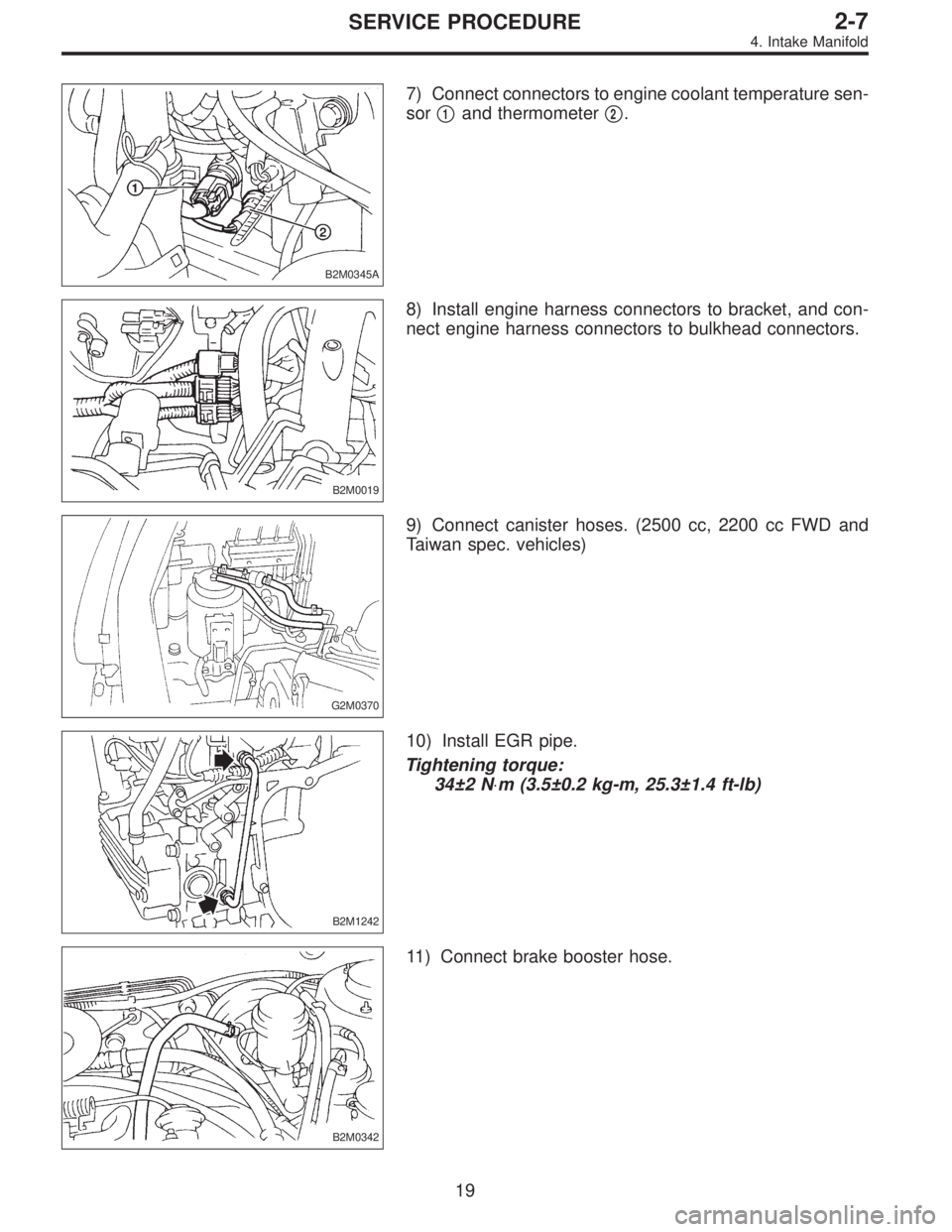
7) Connect connectors to engine coolant temperature sen-
sor�
1and thermometer�2.
B2M0019
8) Install engine harness connectors to bracket, and con-
nect engine harness connectors to bulkhead connectors.
G2M0370
9) Connect canister hoses. (2500 cc, 2200 cc FWD and
Taiwan spec. vehicles)
B2M1242
10) Install EGR pipe.
Tightening torque:
34±2 N⋅m (3.5±0.2 kg-m, 25.3±1.4 ft-lb)
B2M0342
11) Connect brake booster hose.
19
2-7SERVICE PROCEDURE
4. Intake Manifold
Page 489 of 3342
H2M1259A
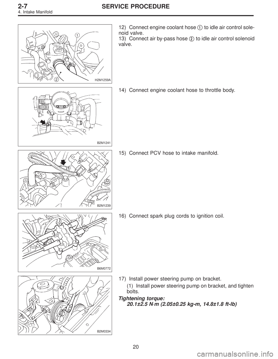
12) Connect engine coolant hose�1to idle air control sole-
noid valve.
13) Connect air by-pass hose�
2to idle air control solenoid
valve.
B2M1241
14) Connect engine coolant hose to throttle body.
B2M1239
15) Connect PCV hose to intake manifold.
B6M0772
16) Connect spark plug cords to ignition coil.
B2M0334
17) Install power steering pump on bracket.
(1) Install power steering pump on bracket, and tighten
bolts.
Tightening torque:
20.1±2.5 N⋅m (2.05±0.25 kg-m, 14.8±1.8 ft-lb)
20
2-7SERVICE PROCEDURE
4. Intake Manifold
Page 491 of 3342
B2M1218
21) Install air intake chamber and connect air hoses.
Tightening torque:
4.9±0.5 N⋅m (0.5±0.05 kg-m, 3.6±0.4 ft-lb)
B2M1213
22) Install air cleaner element.
23) Install air cleaner upper cover and air intake duct as a
unit.
CAUTION:
Before installing air cleaner upper cover, align holes
with protruding portions of air cleaner lower case, then
secure upper cover to lower case.
B2M1225A
24) Connect connector to mass air flow sensor.
B2M0154
5. Engine Coolant Temperature Sensor
A: REMOVAL AND INSTALLATION
1) Remove air intake duct.
G2M0407
2) Disconnect connector from engine coolant temperature
sensor.
3) Remove engine coolant temperature sensor.
22
2-7SERVICE PROCEDURE
4. Intake Manifold - 5. Engine Coolant Temperature Sensor
 Loosen clamps which connect air intake duct to air
intake chamber and mass air flow sensor.
2) Disconnect blow-by hose from air intake duct.
3)")
 Disconnect engine harness connectors from bulkhead
harness connectors, and remove engine harness connec-
tors from bracket.
B2M0345A
23) Disconnect connectors from engine coolant tempera-")
 Install air intake chamber and connect air hoses.
Tightening torque:
4.9±0.5 N⋅m (0.5±0.05 kg-m, 3.6±0.4 ft-lb)
B2M1213
22) Install air cleaner element.
23) Install air cleaner upper")