Page 2274 of 3342

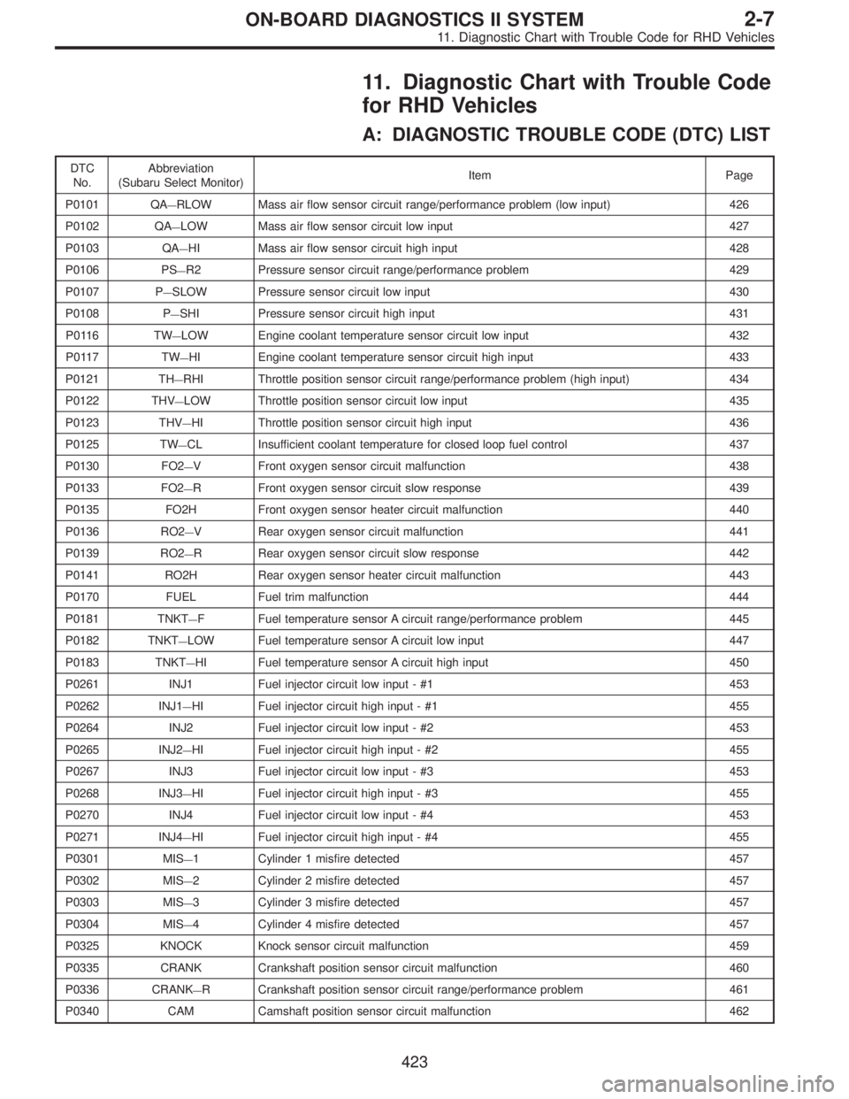
11. Diagnostic Chart with Trouble Code
for RHD Vehicles
A: DIAGNOSTIC TROUBLE CODE (DTC) LIST
DTC
No.Abbreviation
(Subaru Select Monitor)Item Page
P0101 QA
—RLOW Mass air flow sensor circuit range/performance problem (low input) 426
P0102 QA
—LOW Mass air flow sensor circuit low input 427
P0103 QA
—HI Mass air flow sensor circuit high input 428
P0106 PS
—R2 Pressure sensor circuit range/performance problem 429
P0107 P
—SLOW Pressure sensor circuit low input 430
P0108 P
—SHI Pressure sensor circuit high input 431
P0116 TW
—LOW Engine coolant temperature sensor circuit low input 432
P0117 TW
—HI Engine coolant temperature sensor circuit high input 433
P0121 TH
—RHI Throttle position sensor circuit range/performance problem (high input) 434
P0122 THV
—LOW Throttle position sensor circuit low input 435
P0123 THV
—HI Throttle position sensor circuit high input 436
P0125 TW
—CL Insufficient coolant temperature for closed loop fuel control 437
P0130 FO2
—V Front oxygen sensor circuit malfunction 438
P0133 FO2
—R Front oxygen sensor circuit slow response 439
P0135 FO2H Front oxygen sensor heater circuit malfunction 440
P0136 RO2
—V Rear oxygen sensor circuit malfunction 441
P0139 RO2
—R Rear oxygen sensor circuit slow response 442
P0141 RO2H Rear oxygen sensor heater circuit malfunction 443
P0170 FUEL Fuel trim malfunction 444
P0181 TNKT
—F Fuel temperature sensor A circuit range/performance problem 445
P0182 TNKT
—LOW Fuel temperature sensor A circuit low input 447
P0183 TNKT
—HI Fuel temperature sensor A circuit high input 450
P0261 INJ1 Fuel injector circuit low input - #1 453
P0262 INJ1
—HI Fuel injector circuit high input - #1 455
P0264 INJ2 Fuel injector circuit low input - #2 453
P0265 INJ2
—HI Fuel injector circuit high input - #2 455
P0267 INJ3 Fuel injector circuit low input - #3 453
P0268 INJ3
—HI Fuel injector circuit high input - #3 455
P0270 INJ4 Fuel injector circuit low input - #4 453
P0271 INJ4
—HI Fuel injector circuit high input - #4 455
P0301 MIS
—1 Cylinder 1 misfire detected 457
P0302 MIS
—2 Cylinder 2 misfire detected 457
P0303 MIS
—3 Cylinder 3 misfire detected 457
P0304 MIS
—4 Cylinder 4 misfire detected 457
P0325 KNOCK Knock sensor circuit malfunction 459
P0335 CRANK Crankshaft position sensor circuit malfunction 460
P0336 CRANK
—R Crankshaft position sensor circuit range/performance problem 461
P0340 CAM Camshaft position sensor circuit malfunction 462
423
2-7ON-BOARD DIAGNOSTICS II SYSTEM
11. Diagnostic Chart with Trouble Code for RHD Vehicles
Page 2283 of 3342
B2M1067
H: DTC P0116
—ENGINE COOLANT TEMPERATURE
SENSOR CIRCUIT LOW INPUT—
WIRING DIAGRAM:
B2M0539
NOTE:
Check engine coolant temperature sensor circuit.
432
2-7ON-BOARD DIAGNOSTICS II SYSTEM
11. Diagnostic Chart with Trouble Code for RHD Vehicles
Page 2284 of 3342
B2M1068
I: DTC P0117
—ENGINE COOLANT TEMPERATURE
SENSOR CIRCUIT HIGH INPUT—
WIRING DIAGRAM:
B2M0539
NOTE:
Check engine coolant temperature sensor circuit.
433
2-7ON-BOARD DIAGNOSTICS II SYSTEM
11. Diagnostic Chart with Trouble Code for RHD Vehicles
Page 3289 of 3342
![SUBARU LEGACY 1997 Service Repair Manual 7. Electrical Unit Location
Electrical unit Refer to;
A.B.S. control module 4-4a [T300]
A.B.S. G sensor (MT) 4-4a [T300]
A/C compressor relay�
7
A/C fuse�11
A/C main fan relay 1�10
A/C main fan relay SUBARU LEGACY 1997 Service Repair Manual 7. Electrical Unit Location
Electrical unit Refer to;
A.B.S. control module 4-4a [T300]
A.B.S. G sensor (MT) 4-4a [T300]
A/C compressor relay�
7
A/C fuse�11
A/C main fan relay 1�10
A/C main fan relay](/manual-img/17/57434/w960_57434-3288.png)
7. Electrical Unit Location
Electrical unit Refer to;
A.B.S. control module 4-4a [T300]
A.B.S. G sensor (MT) 4-4a [T300]
A/C compressor relay�
7
A/C fuse�11
A/C main fan relay 1�10
A/C main fan relay 2�8
A/C pressure switch�2
A/C sub fan relay 2�9
ATF temperature sensor 2-7 [T2B1]
Blower motor resistor�
26
Blower relay�13
Camshaft position sensor 2-7 [T2A2]
Check connector�
25
Clutch switch (MT) 6-2 [T300]
Crankshaft position sensor 2-7 [T2A2]
Cruise control module 6-2 [T300]
Cruise control pump 6-2 [T300]
Data link connector (for OBD-II G.S.T.) 2-7 [T2A1]
Data link connector (for S.S.M.) 2-7 [T2A1]
Diagnosis connector 4-4a [T300]
Diagnosis terminal (Ground) 4-4a [T300]
Door lock timer�
27
Engine control module 2-7 [T2A1]
Engine coolant temperature sensor 2-7 [T2A2]
Engine hood switch (Security) 6-2 [K6A0]
Evaporator thermoswitch�
29
F/B�15
FRESH/RECIRC actuator�28
Fuel pump relay 2-7 [T2A3]
Fuel gauge module�
31
Fuel gauge sub module (AWD)�32
FWD switch (AT)�1
Headlight alarm relay (Security) 6-2 [K6A0]
Headlight relay LH�
5
Headlight relay RH�6
Horn relay�14
Electrical unit Refer to;
Hydraulic unit (A.B.S.) 4-4a [T300]
Ignition coil 2-7 [T2A3]
Ignitor 2-7 [T2A3]
Idle air control solenoid valve 2-7 [T2A3]
Illumination control module�
21
Inhibitor switch 6-2 [T300]
Knock sensor 2-7 [T2A2]
Main fan relay�
19
Main relay 2-7 [T2A3]
Mass air flow sensor 2-7 [T2A2]
Mode actuator�
12
M/B�4
Oil pressure switch�3
Oxygen sensor 2-7 [T2A2]
Pedal stroke sensor (T.C.S.) 4-4b [T300]
Power window and sunroof relay�
24
Power window circuit breaker�23
Purge control solenoid valve 2-7 [T2A3]
Rear defogger relay�
17
Seat belt timer�20
Security control module 6-2 [K6A0]
Shift lock control module�
22
Starter interrupt relay (Security) 6-2 [K6A0]
Stop & brake switch (With cruise con-
trol)6-2 [T300]
Sunroof control module�
30
Tail and illumination relay�18
T.C.S. control module 4-4b [T300]
T.C.S. motor relay 4-4b [T300]
T.C.S. valve relay 4-4b [T300]
Throttle position sensor 2-7 [T2A2]
Test mode connector 2-7 [T2A1]
Transmission control module 2-7 [T2B1]
Turn & hazard module�
16
Vehicle speed sensor 1 2-7 [T2B1]
Vehicle speed sensor 2 2-7 [T2B1]
11 0
6-3WIRING DIAGRAM
7. Electrical Unit Location
Page 3305 of 3342

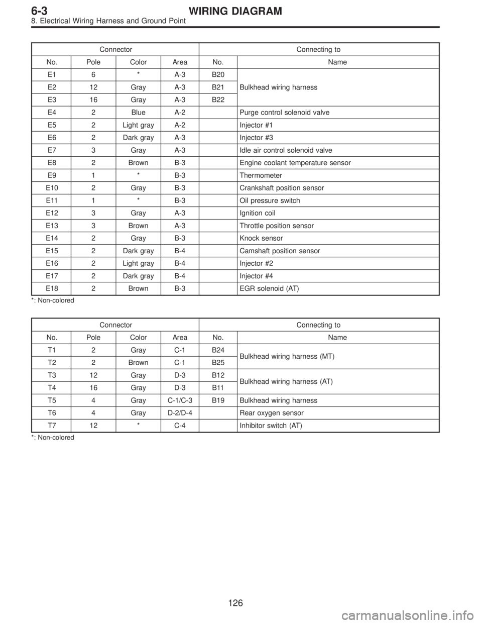
Connector Connecting to
No. Pole Color Area No. Name
E1 6 * A-3 B20
Bulkhead wiring harness E2 12 Gray A-3 B21
E3 16 Gray A-3 B22
E4 2 Blue A-2 Purge control solenoid valve
E5 2 Light gray A-2 Injector #1
E6 2 Dark gray A-3 Injector #3
E7 3 Gray A-3 Idle air control solenoid valve
E8 2 Brown B-3 Engine coolant temperature sensor
E9 1 * B-3 Thermometer
E10 2 Gray B-3 Crankshaft position sensor
E11 1 * B-3 Oil pressure switch
E12 3 Gray A-3 Ignition coil
E13 3 Brown A-3 Throttle position sensor
E14 2 Gray B-3 Knock sensor
E15 2 Dark gray B-4 Camshaft position sensor
E16 2 Light gray B-4 Injector #2
E17 2 Dark gray B-4 Injector #4
E18 2 Brown B-3 EGR solenoid (AT)
*: Non-colored
Connector Connecting to
No. Pole Color Area No. Name
T1 2 Gray C-1 B24
Bulkhead wiring harness (MT)
T2 2 Brown C-1 B25
T3 12 Gray D-3 B12
Bulkhead wiring harness (AT)
T4 16 Gray D-3 B11
T5 4 Gray C-1/C-3 B19 Bulkhead wiring harness
T6 4 Gray D-2/D-4 Rear oxygen sensor
T7 12 * C-4 Inhibitor switch (AT)
*: Non-colored
126
6-3WIRING DIAGRAM
8. Electrical Wiring Harness and Ground Point