Page 492 of 3342
B2M1218
21) Install air intake chamber and connect air hoses.
Tightening torque:
4.9±0.5 N⋅m (0.5±0.05 kg-m, 3.6±0.4 ft-lb)
B2M1213
22) Install air cleaner element.
23) Install air cleaner upper cover and air intake duct as a
unit.
CAUTION:
Before installing air cleaner upper cover, align holes
with protruding portions of air cleaner lower case, then
secure upper cover to lower case.
B2M1225A
24) Connect connector to mass air flow sensor.
B2M0154
5. Engine Coolant Temperature Sensor
A: REMOVAL AND INSTALLATION
1) Remove air intake duct.
G2M0407
2) Disconnect connector from engine coolant temperature
sensor.
3) Remove engine coolant temperature sensor.
22
2-7SERVICE PROCEDURE
4. Intake Manifold - 5. Engine Coolant Temperature Sensor
Page 493 of 3342
G2M0407
4) Installation is in the reverse order of removal.
Tightening torque:
25±3 N⋅m (2.5±0.3 kg-m, 18.1±2.2 ft-lb)
G2M0408
6. Crankshaft Position Sensor
A: REMOVAL AND INSTALLATION
1) Remove bolt which install crankshaft position sensor to
cylinder block.
G2M0409
2) Remove crankshaft position sensor, and disconnect
connector from it.
G2M0408
3) Installation is in the reverse order of removal.
Tightening torque:
6.4±0.5 N⋅m (0.65±0.05 kg-m, 4.7±0.4 ft-lb)
B2M0154
7. Front Oxygen Sensor
A: REMOVAL
1) Remove air intake duct.
23
2-7SERVICE PROCEDURE
5. Engine Coolant Temperature Sensor - 7. Front Oxygen Sensor
Page 494 of 3342
G2M0407
4) Installation is in the reverse order of removal.
Tightening torque:
25±3 N⋅m (2.5±0.3 kg-m, 18.1±2.2 ft-lb)
G2M0408
6. Crankshaft Position Sensor
A: REMOVAL AND INSTALLATION
1) Remove bolt which install crankshaft position sensor to
cylinder block.
G2M0409
2) Remove crankshaft position sensor, and disconnect
connector from it.
G2M0408
3) Installation is in the reverse order of removal.
Tightening torque:
6.4±0.5 N⋅m (0.65±0.05 kg-m, 4.7±0.4 ft-lb)
B2M0154
7. Front Oxygen Sensor
A: REMOVAL
1) Remove air intake duct.
23
2-7SERVICE PROCEDURE
5. Engine Coolant Temperature Sensor - 7. Front Oxygen Sensor
Page 495 of 3342
G2M0407
4) Installation is in the reverse order of removal.
Tightening torque:
25±3 N⋅m (2.5±0.3 kg-m, 18.1±2.2 ft-lb)
G2M0408
6. Crankshaft Position Sensor
A: REMOVAL AND INSTALLATION
1) Remove bolt which install crankshaft position sensor to
cylinder block.
G2M0409
2) Remove crankshaft position sensor, and disconnect
connector from it.
G2M0408
3) Installation is in the reverse order of removal.
Tightening torque:
6.4±0.5 N⋅m (0.65±0.05 kg-m, 4.7±0.4 ft-lb)
B2M0154
7. Front Oxygen Sensor
A: REMOVAL
1) Remove air intake duct.
23
2-7SERVICE PROCEDURE
5. Engine Coolant Temperature Sensor - 7. Front Oxygen Sensor
Page 504 of 3342
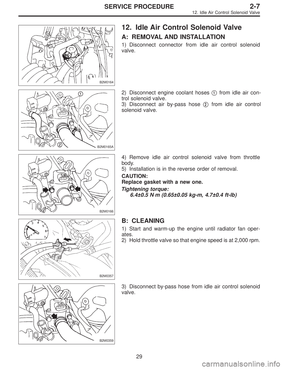
B2M0164
12. Idle Air Control Solenoid Valve
A: REMOVAL AND INSTALLATION
1) Disconnect connector from idle air control solenoid
valve.
B2M0165A
2) Disconnect engine coolant hoses�1from idle air con-
trol solenoid valve.
3) Disconnect air by-pass hose�
2from idle air control
solenoid valve.
B2M0166
4) Remove idle air control solenoid valve from throttle
body.
5) Installation is in the reverse order of removal.
CAUTION:
Replace gasket with a new one.
Tightening torque:
6.4±0.5 N⋅m (0.65±0.05 kg-m, 4.7±0.4 ft-lb)
B2M0357
B: CLEANING
1) Start and warm-up the engine until radiator fan oper-
ates.
2) Hold throttle valve so that engine speed is at 2,000 rpm.
B2M0359
3) Disconnect by-pass hose from idle air control solenoid
valve.
29
2-7SERVICE PROCEDURE
12. Idle Air Control Solenoid Valve
Page 517 of 3342
B2M1680A
3) Remove band clip which fastens engine harness to
engine coolant hose.
B2M1681
4) Disconnect knock sensor connector.
B2M1682
5) Remove knock sensor from cylinder block.
G6M0095
2. 2500 cc MODEL
1) Disconnect battery ground cable from battery ground
terminal.
B2M1683
2) Remove air intake chamber.
35
2-7SERVICE PROCEDURE
19. Knock Sensor
Page 518 of 3342
B2M1179D
3) Remove operating cylinder. (MT vehicle only)
B2M1684
NOTE:
Place the operating cylinder where it will not interfere with
the work in process.
B2M1685A
4) Remove band clip which fastens engine harness to
engine coolant hose.
B2M1686
5) Disconnect knock sensor connector.
B2M1682
6) Remove knock sensor from cylinder block.
36
2-7SERVICE PROCEDURE
19. Knock Sensor
Page 519 of 3342
B2M1682A
B: INSTALLATION
1. 2200 cc MODEL
1) Install knock sensor to cylinder block.
Tightening torque:
23.5±2.9 N⋅m (2.4±0.3 kg-m, 17.3±2.1 ft-lb)
NOTE:
The extraction area of the knock sensor cord must be posi-
tioned at a 45°angle relative to the engine rear.
B2M1681
2) Connect knock sensor connector.
B2M1687A
NOTE:
The knock sensor cord must pass between the engine
harness and engine coolant hose.
B2M1680A
3) Fasten engine harness to engine coolant hose with
band clip.
NOTE:
Make sure that the throttle linkage does not interfere with
other parts in the operating area.
B2M1679
4) Install air intake chamber.
37
2-7SERVICE PROCEDURE
19. Knock Sensor
 Install air intake chamber and connect air hoses.
Tightening torque:
4.9±0.5 N⋅m (0.5±0.05 kg-m, 3.6±0.4 ft-lb)
B2M1213
22) Install air cleaner element.
23) Install air cleaner upper")
 Installation is in the reverse order of removal.
Tightening torque:
25±3 N⋅m (2.5±0.3 kg-m, 18.1±2.2 ft-lb)
G2M0408
6. Crankshaft Position Sensor
A: REMOVAL AND INSTALLATION
1) Remove")
 Installation is in the reverse order of removal.
Tightening torque:
25±3 N⋅m (2.5±0.3 kg-m, 18.1±2.2 ft-lb)
G2M0408
6. Crankshaft Position Sensor
A: REMOVAL AND INSTALLATION
1) Remove")
 Installation is in the reverse order of removal.
Tightening torque:
25±3 N⋅m (2.5±0.3 kg-m, 18.1±2.2 ft-lb)
G2M0408
6. Crankshaft Position Sensor
A: REMOVAL AND INSTALLATION
1) Remove")
 Remove band clip which fastens engine harness to
engine coolant hose.
B2M1681
4) Disconnect knock sensor connector.
B2M1682
5) Remove knock sensor from cylinder block.
G6M0095
2. 2500 cc M")
 Remove operating cylinder. (MT vehicle only)
B2M1684
NOTE:
Place the operating cylinder where it will not interfere with
the work in process.
B2M1685A
4) Remove band clip which fastens eng")
 Install knock sensor to cylinder block.
Tightening torque:
23.5±2.9 N⋅m (2.4±0.3 kg-m, 17.3±2.1 ft-lb)
NOTE:
The extraction area of the knock sensor c")