Page 701 of 3342

B3M0337
B: ASSEMBLY
Assembly is in the reverse order of disassembly.
Do the following:
�Install thrust washer with chamfered side of inner perim-
eter facing the side gear.
�Install adjusting washer with chamfered side of inner
perimeter facing the viscous coupling using ST.
ST 499547300 INSTALLER SET
B3M0095A
1) Selection of snap ring (Inner-110)
(1) After assembling, using a thickness gauge mea-
sure clearance between snap ring�
1and center differ-
ential case.
Clearance:
0—0.15 mm (0—0.0059 in)
(2) If the measurement is not within the specification,
select suitable snap ring.
Snap ring (Inner-110)
Part No. Thickness mm (in)
805100061 2.10 (0.0827)
805100062 2.21 (0.0870)
805100063 2.32 (0.0913)
B3M0096A
2) Selection of adjusting washer (Backlash adjustment)
(1) After assembling, set up a ST1 and ST2 to end of
viscous coupling shaft. Move viscous coupling up and
down, and measure backlash in the axial direction.
ST1 498247001 MAGNET BASE
ST2 498247100 DIAL GAUGE
Backlash:
0.62—0.86 mm (0.0244—0.0339 in)
(2) If the measurement is not within the specification,
select suitable washer.
Adjusting washer (45 x 62 x t)
Part No. Thickness mm (in)
803045041 1.60 (0.0630)
803045042 1.80 (0.0709)
803045043 2.00 (0.0787)
803045044 2.20 (0.0866)
803045045 2.40 (0.0945)
67
3-1SERVICE PROCEDURE
8. Center Differential (AWD Model)
Page 702 of 3342
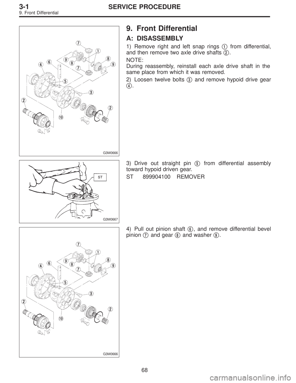
G3M0666
9. Front Differential
A: DISASSEMBLY
1) Remove right and left snap rings�1from differential,
and then remove two axle drive shafts�
2.
NOTE:
During reassembly, reinstall each axle drive shaft in the
same place from which it was removed.
2) Loosen twelve bolts�
3and remove hypoid drive gear
�
4.
G3M0667
3) Drive out straight pin�5from differential assembly
toward hypoid driven gear.
ST 899904100 REMOVER
G3M0666
4) Pull out pinion shaft�6, and remove differential bevel
pinion�
7and gear�8and washer�9.
68
3-1SERVICE PROCEDURE
9. Front Differential
Page 703 of 3342
G3M0668
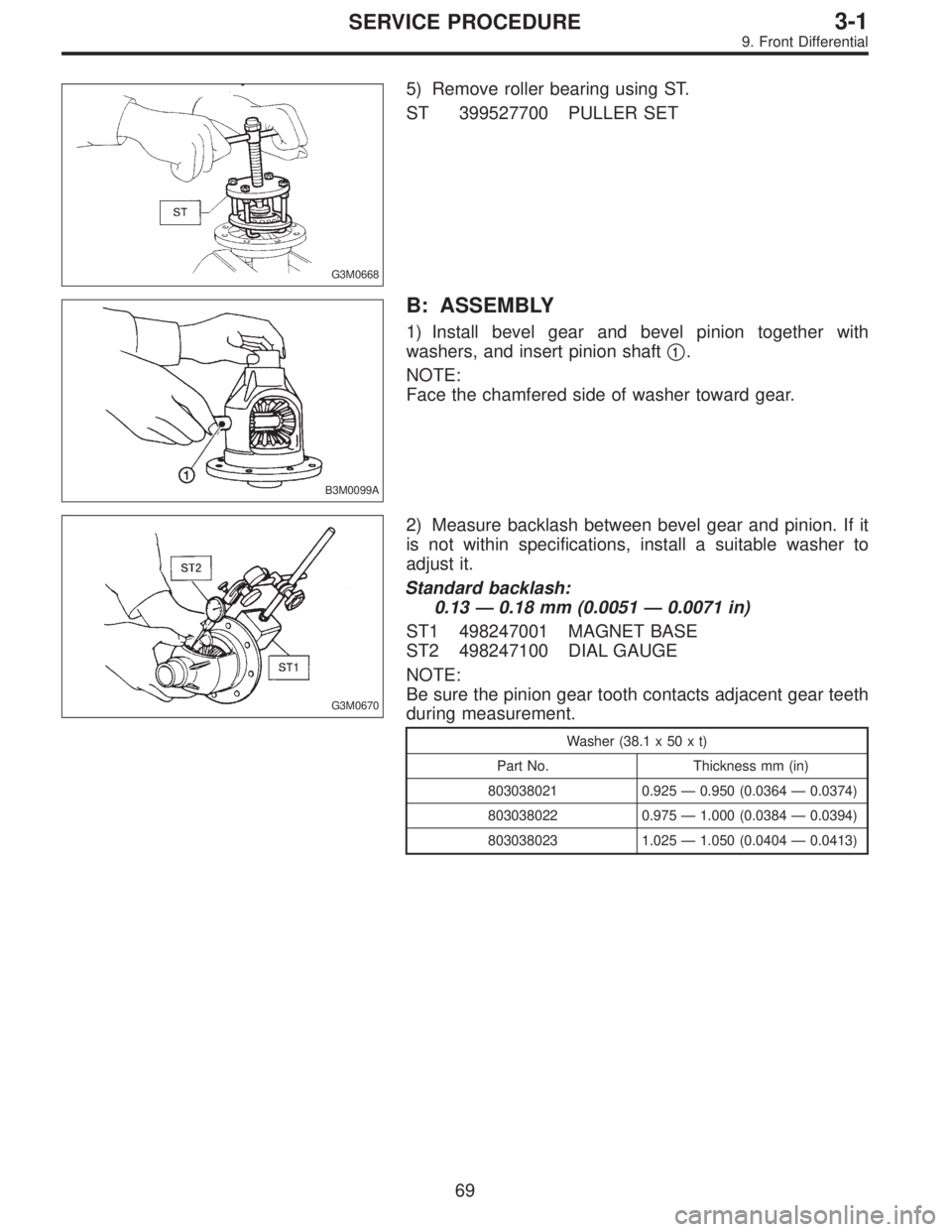
5) Remove roller bearing using ST.
ST 399527700 PULLER SET
B3M0099A
B: ASSEMBLY
1) Install bevel gear and bevel pinion together with
washers, and insert pinion shaft�
1.
NOTE:
Face the chamfered side of washer toward gear.
G3M0670
2) Measure backlash between bevel gear and pinion. If it
is not within specifications, install a suitable washer to
adjust it.
Standard backlash:
0.13—0.18 mm (0.0051—0.0071 in)
ST1 498247001 MAGNET BASE
ST2 498247100 DIAL GAUGE
NOTE:
Be sure the pinion gear tooth contacts adjacent gear teeth
during measurement.
Washer (38.1 x 50 x t)
Part No. Thickness mm (in)
803038021 0.925—0.950 (0.0364—0.0374)
803038022 0.975—1.000 (0.0384—0.0394)
803038023 1.025—1.050 (0.0404—0.0413)
69
3-1SERVICE PROCEDURE
9. Front Differential
Page 704 of 3342
G3M0666
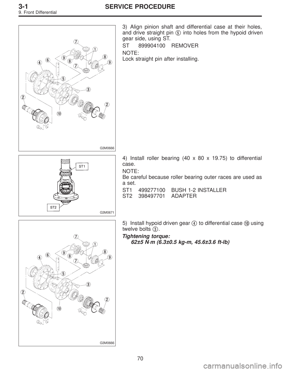
3) Align pinion shaft and differential case at their holes,
and drive straight pin�
5into holes from the hypoid driven
gear side, using ST.
ST 899904100 REMOVER
NOTE:
Lock straight pin after installing.
G3M0671
4) Install roller bearing (40 x 80 x 19.75) to differential
case.
NOTE:
Be careful because roller bearing outer races are used as
a set.
ST1 499277100 BUSH 1-2 INSTALLER
ST2 398497701 ADAPTER
G3M0666
5) Install hypoid driven gear�4to differential case�10using
twelve bolts�
3.
Tightening torque:
62±5 N⋅m (6.3±0.5 kg-m, 45.6±3.6 ft-lb)
70
3-1SERVICE PROCEDURE
9. Front Differential
Page 705 of 3342
B3M0100
6) Position drive axle shaft in differential case and hold it
with outer snap ring (28). Using a thickness gauge, mea-
sure clearance between the shaft and case is within speci-
fications.
Clearance:
0—0.2 mm (0—0.008 in)
If it is not within specifications, replace snap ring with a
suitable one.
Snap ring (Outer-28)
Part No. Thickness mm (in)
805028011 1.05 (0.0413)
805028012 1.20 (0.0472)
71
3-1SERVICE PROCEDURE
9. Front Differential
Page 708 of 3342

1. Automatic Transmission and
Differential
A: SPECIFICATIONS
Torque
converter
clutchType Symmetric, 3 element, single stage, 2 phase torque converter clutch coupling
Stall torque ratio2200 cc 2.1 — 2.3
2500 cc 1.8 — 2.0
OUTBACK 2.2 — 2.4
Nominal diameter2200 cc 236 mm (9.29 in)
2500 cc 246 mm (9.69 in)
Stall speed (at sea level)2200 cc 2,200 — 2,600 rpm
2500 cc 2,200 — 2,600 rpm
OUTBACK 2,300 — 2,700 rpm
One-way clutch Sprague type one-way clutch
Automatic
transmissionTransmissionType 4-forward, 1-reverse, double-row planetary gears
Control elementMulti-plate clutch 4 sets
Multi-plate brake 1 set
Band brake 1 set
One-way clutch (sprague type) 2 sets
Gear ratio1st2200 cc 2.785
2500 cc 3.027
2nd2200 cc 1.545
2500 cc 1.619
3rd 1.000
4th 0.694
Reverse 2.272
Tooth number of
planetary gearFront sun gear 33
Front pinion 21
Front internal gear 75
Rear sun gear2200 cc 42
2500 cc 37
Rear pinion2200 cc 17
2500 cc 19
Rear internal gear 75
Clutch number of reverse
clutchDrive plate & driven plate 2
Clutch number of
high clutchDrive plate & driven plate2200 cc ... 4
2500 cc ... 5
Clutch number of forward
clutchDrive plate & driven plate 5
Clutch number of
overrunning clutchDrive plate & driven plate 3
Clutch number of low &
reverse brakeDrive plate & driven plateExcept OUTBACK ... 5
OUTBACK ... 6
Selector positionP (Park)Transmission in neutral, output member
immovable, and engine start possible
R (Reverse) Transmission in reverse for backing
N (Neutral) Transmission in neutral, and engine start possible
D (Drive) Automatic gear change 1st
+
,2nd+
,3rd+
,4th
3 (3rd) Automatic gear change 1st+
,2nd+
,3rd+4th
2 (2nd)2nd gear locked
(Deceleration possible 4th,3rd,2nd)
1 (1st)1st gear locked
(Deceleration possible 4th,3rd,2nd,1st)
Control method Hydraulic remote control
2
3-2SPECIFICATIONS AND SERVICE DATA
1. Automatic Transmission and Differential
Page 709 of 3342

Automatic
transmissionOil pumpType Variable-capacity type vane pump
Driving method Driven by engine
Number of vanes 9 pieces
Hydraulic
controlTy p eElectronic/hydraulic control
[Four forward speed changes by electrical signals of car speed
and accelerator (throttle) opening]
Fluid Dexron II or Dexron III type Automatic transmission fluid
Fluid
capacity2200 cc 7.9�(8.4 US qt, 7.0 Imp qt)
2500 cc 9.5�(10.0 US qt, 8.4 Imp qt)
LubricationLubrication system Forced feed lubrication with oil pump
Oil Automatic transmission fluid (above mentioned.)
Cooling Cooling system Liquid-cooled cooler incorporated in radiator
HarnessInhibitor switch 12 poles
Transmission harnessFWD ... 11 poles
AWD ... 13 poles
TransferTransfer clutch Hydraulic multi-plate clutch
Clutch number of transfer clutch Drive plate & driven plate 5
Control method Electronic, hydraulic type
LubricantThe same Automatic Transmission Fluid used in automatic
transmission.
1st reduction gear ratio 1.000 (53/53)
Final
reductionFinal gear
ratioFront driveFWD 3.900 (39/10)
AWD2200 cc 4.111 (37/9)
2500 cc 4.444 (40/9)
Speedometer gear ratio2200 cc & LSi 0.83 (19/23)
GT 0.80 (20/25)
OUTBACK 0.76 (19/25)
Lubrication oilAPI, GL-5
Oil capacity Front drive 1.2�(1.3 US qt, 1.1 Imp qt)
ATF cooling
systemRadiation capacity 1.651 kW (1,420 kcal/h, 5,635 BTU/h)
3
3-2SPECIFICATIONS AND SERVICE DATA
1. Automatic Transmission and Differential
Page 710 of 3342
B: ADJUSTING PARTS
G3M0774
4
3-2SPECIFICATIONS AND SERVICE DATA
1. Automatic Transmission and Differential
 Position drive axle shaft in differential case and hold it
with outer snap ring (28). Using a thickness gauge, mea-
sure clearance between the shaft and case is within speci-
fications.
Cle")
