Page 685 of 3342
G3M0611
7) Remove 1st driven gear, 2nd gear bushing, gear and
hub using ST1 and ST2.
NOTE:
Replace gear and hub if necessary. Do not attempt to dis-
assemble if at all possible because they must engage at a
specified point. If they have to be disassembled, mark the
engaging point beforehand.
ST1 499757002 SNAP RING PRESS
ST2 899714110 REMOVER
8) Remove sub gear for 1st driven gear.
B3M0077A
B: ASSEMBLY
1. GEAR AND HUB ASSEMBLY (2200 cc MODEL)
NOTE:
Position open ends of springs 120°apart.
�
A: 1st gear side
�
B: 2nd gear side
�
C: Flush surface
�
D: Stepped surface
B3M0431A
2. GEAR AND HUB ASSEMBLY (2500 cc MODEL)
Assemble gear and hub assembly.
NOTE:
�Use new gear and hub assembly, if gear or hub have
been replaced.
�Be sure the insert keys are correctly located in the insert
key grooves�
1inside the reverse driven gear�2.
B3M0077A
�A: 1st gear side
�
B: 2nd gear side
�
C: Flush surface
�
D: Stepped surface
52
3-1SERVICE PROCEDURE
5. Drive Pinion Assembly (AWD Model)
Page 686 of 3342

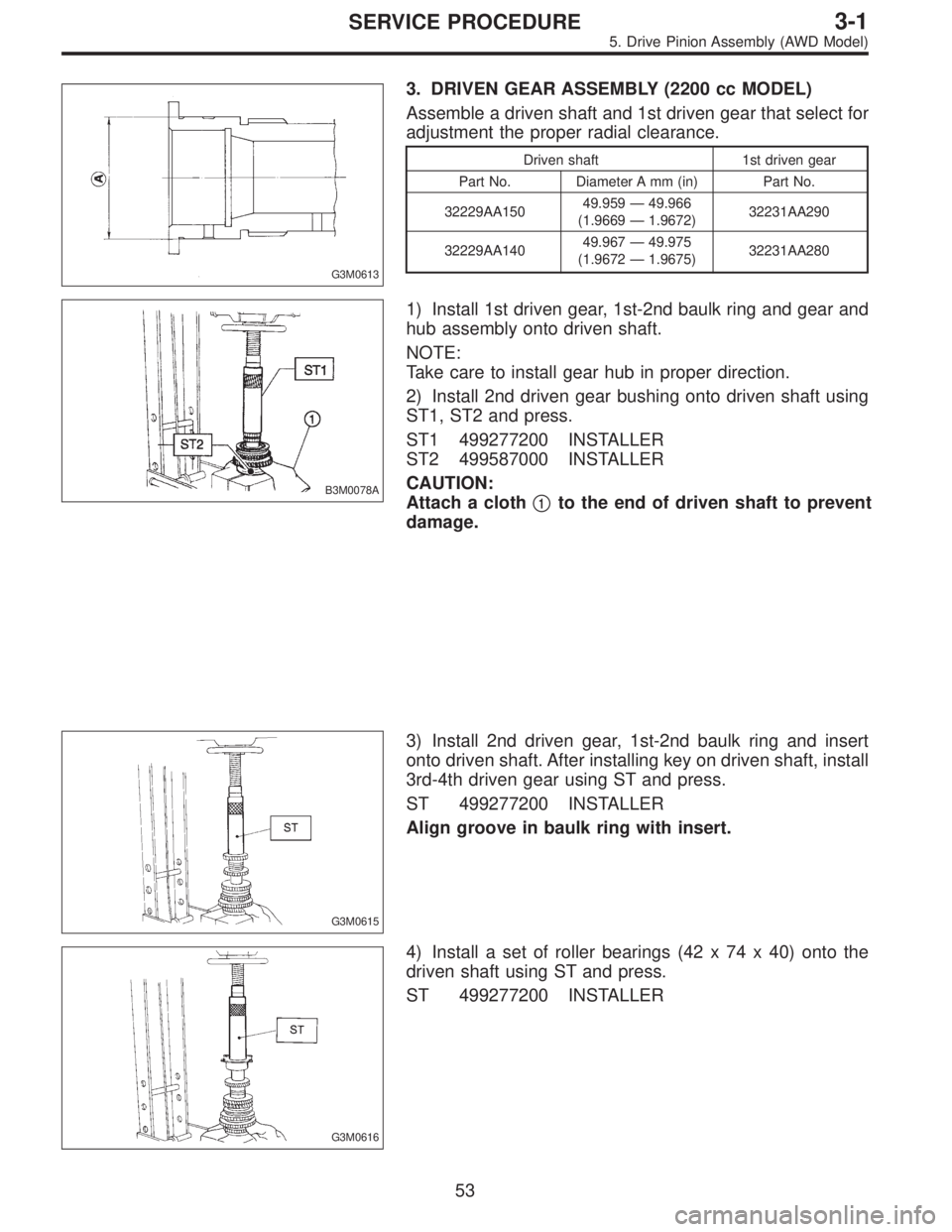
G3M0613
3. DRIVEN GEAR ASSEMBLY (2200 cc MODEL)
Assemble a driven shaft and 1st driven gear that select for
adjustment the proper radial clearance.
Driven shaft 1st driven gear
Part No. Diameter A mm (in) Part No.
32229AA15049.959—49.966
(1.9669—1.9672)32231AA290
32229AA14049.967—49.975
(1.9672—1.9675)32231AA280
B3M0078A
1) Install 1st driven gear, 1st-2nd baulk ring and gear and
hub assembly onto driven shaft.
NOTE:
Take care to install gear hub in proper direction.
2) Install 2nd driven gear bushing onto driven shaft using
ST1, ST2 and press.
ST1 499277200 INSTALLER
ST2 499587000 INSTALLER
CAUTION:
Attach a cloth�
1to the end of driven shaft to prevent
damage.
G3M0615
3) Install 2nd driven gear, 1st-2nd baulk ring and insert
onto driven shaft. After installing key on driven shaft, install
3rd-4th driven gear using ST and press.
ST 499277200 INSTALLER
Align groove in baulk ring with insert.
G3M0616
4) Install a set of roller bearings (42 x 74 x 40) onto the
driven shaft using ST and press.
ST 499277200 INSTALLER
53
3-1SERVICE PROCEDURE
5. Drive Pinion Assembly (AWD Model)
Page 687 of 3342
G3M0617
5) Position woodruff key in groove on the rear of driven
shaft. Install 5th driven gear onto drive shaft using ST and
press.
ST 499277200 INSTALLER
G3M0618
6) Install lock washer (42 x 53 x 2). Install lock nut (42 x
13) and tighten to the specified torque using ST.
ST 499987300 SOCKET WRENCH (50)
Tightening torque:
265±10 N⋅m (27±1 kg-m, 195±7 ft-lb)
B3M0079A
NOTE:
�Stake lock nut at two points.
�Using spring balancer, check that starting torque of roller
bearing�
2is 0.1 to 1.5 N⋅m (1 to 15 kg-cm, 0.9 to 13.0 in-
lb).
G3M0613
4. DRIVEN GEAR ASSEMBLY (2500 cc MODEL)
Assemble a driven shaft and 1st driven gear that select for
adjustment the proper radial clearance.
Driven shaft 1st driven gear
Part No. Diameter A mm (in) Part No.
32229AA15049.959—49.966
(1.9669—1.9672)32231AA290
32229AA14049.967—49.975
(1.9672—1.9675)32231AA280
54
3-1SERVICE PROCEDURE
5. Drive Pinion Assembly (AWD Model)
Page 688 of 3342
B3M0078A
1) Install sub gear to 1st driven gear.
2) Install 1st driven gear, 1st baulk ring, gear and hub
assembly onto driven shaft.
NOTE:
Take care to install gear hub in proper direction.
3) Install 2nd driven gear bushing onto driven shaft using
ST1, ST2 and press.
ST1 499277200 INSTALLER
ST2 499587000 INSTALLER
CAUTION:
Attach a cloth�
1to the end of driven shaft to prevent
damage.
NOTE:
When press fitting, align oil holes of shaft and bush.
B3M0426A
4) Install 2nd driven gear�1, inner baulk ring�2, synchro
cone�
3, outer baulk ring�4and insert onto driven shaft.
G3M0615
5) After installing key on driven shaft, install 3rd-4th driven
gear using ST and press.
ST 499277200 INSTALLER
NOTE:
Align groove in baulk ring with insert.
G3M0616
6) Install a set of roller bearings (42 x 74 x 40) onto the
driven shaft using ST and press.
ST 499277200 INSTALLER
55
3-1SERVICE PROCEDURE
5. Drive Pinion Assembly (AWD Model)
Page 689 of 3342
G3M0617
7) Position woodruff key in groove on the rear of driven
shaft. Install 5th driven gear onto drive shaft using ST and
press.
ST 499277200 INSTALLER
G3M0618
8) Install lock washer (42 x 53 x 2). Install lock nut (42 x
13) and tighten to the specified torque using ST.
ST 499987300 SOCKET WRENCH (50)
Tightening torque:
265±10 N⋅m (27±1 kg-m, 195±7 ft-lb)
B3M0079A
NOTE:
�Stake lock nut at two points.
�Using spring balancer, check that starting torque of roller
bearing�
2is 0.1 to 1.5 N⋅m (1 to 15 kg-cm, 0.9 to 13.0 in-
lb).
B3M0080A
5. DRIVE PINION SHAFT
1) Install roller bearing onto drive pinion. Install washer�
1
(33 x 50 x 5) using ST1, ST2 and press.
ST1 499277100 BUSH 1-2 INSTALLER
ST2 499277200 INSTALLER
B3M0081A
NOTE:
When installing roller bearing�
2, note its directions (front
and rear) because knock pin hole�
3in outer race is offset.
56
3-1SERVICE PROCEDURE
5. Drive Pinion Assembly (AWD Model)
Page 690 of 3342

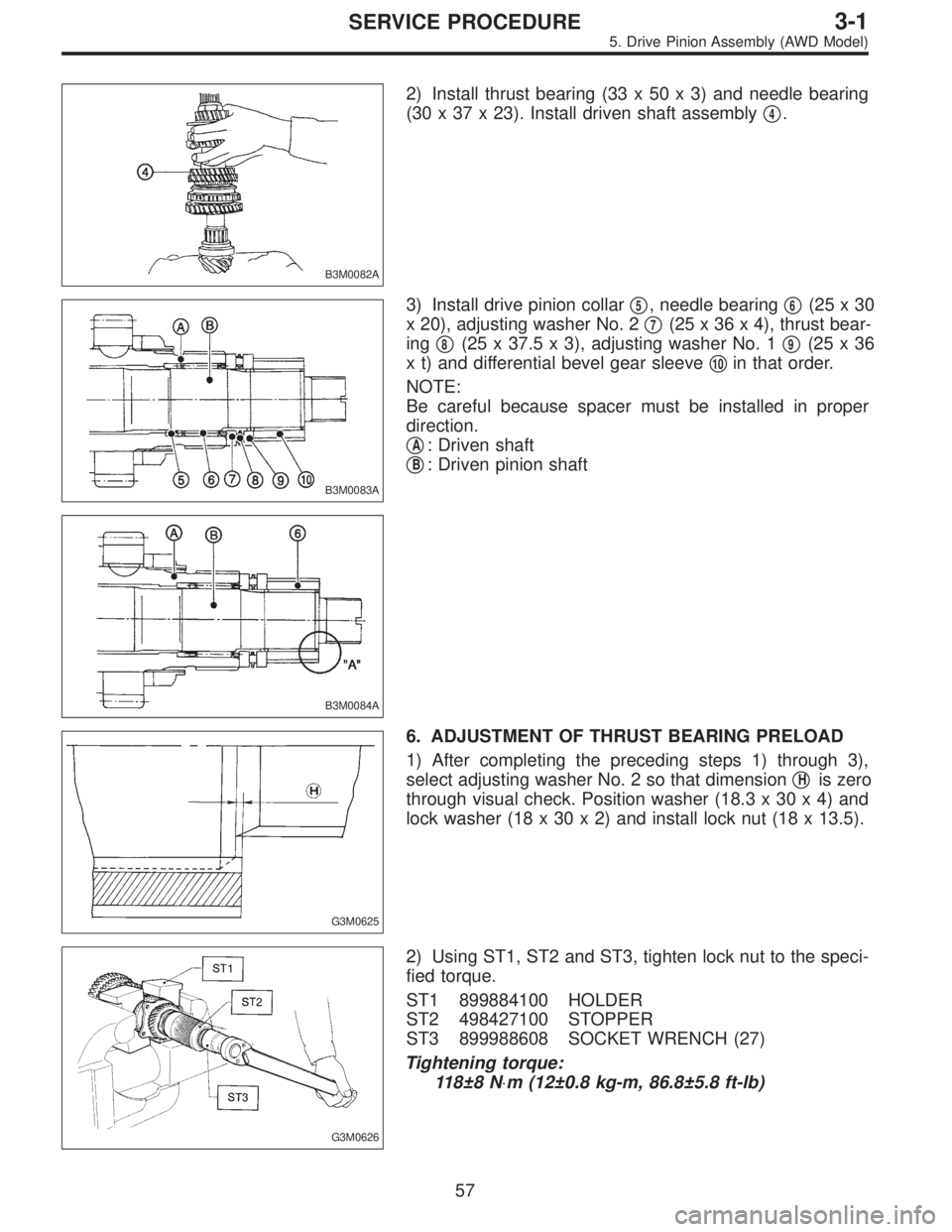
B3M0082A
2) Install thrust bearing (33 x 50 x 3) and needle bearing
(30 x 37 x 23). Install driven shaft assembly�
4.
B3M0083A
3) Install drive pinion collar�5, needle bearing�6(25x30
x 20), adjusting washer No. 2�
7(25 x 36 x 4), thrust bear-
ing�
8(25 x 37.5 x 3), adjusting washer No. 1�9(25x36
x t) and differential bevel gear sleeve�
10in that order.
NOTE:
Be careful because spacer must be installed in proper
direction.
�
A: Driven shaft
�
B: Driven pinion shaft
B3M0084A
G3M0625
6. ADJUSTMENT OF THRUST BEARING PRELOAD
1) After completing the preceding steps 1) through 3),
select adjusting washer No. 2 so that dimension�
His zero
through visual check. Position washer (18.3 x 30 x 4) and
lock washer (18 x 30 x 2) and install lock nut (18 x 13.5).
G3M0626
2) Using ST1, ST2 and ST3, tighten lock nut to the speci-
fied torque.
ST1 899884100 HOLDER
ST2 498427100 STOPPER
ST3 899988608 SOCKET WRENCH (27)
Tightening torque:
118±8 N⋅m (12±0.8 kg-m, 86.8±5.8 ft-lb)
57
3-1SERVICE PROCEDURE
5. Drive Pinion Assembly (AWD Model)
Page 691 of 3342

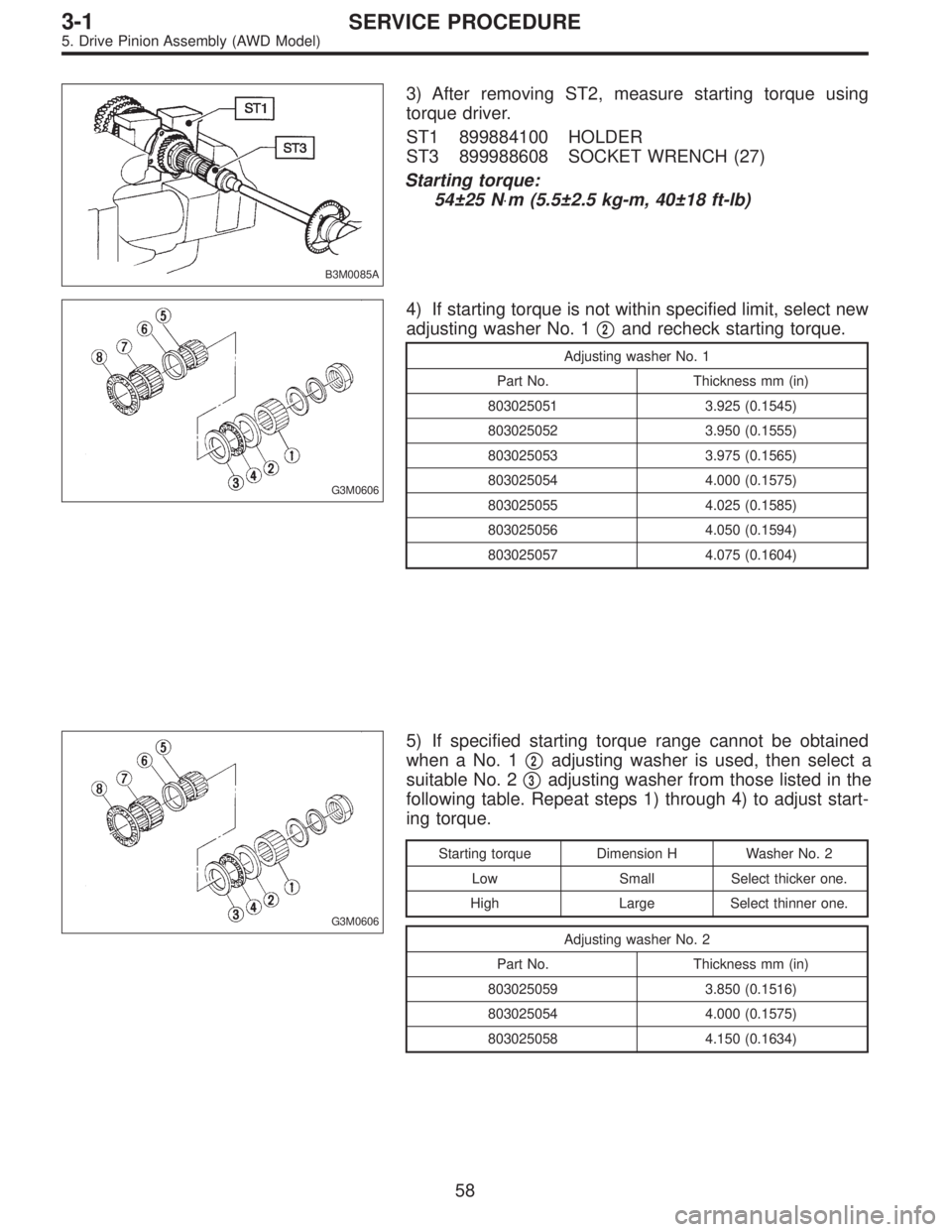
B3M0085A
3) After removing ST2, measure starting torque using
torque driver.
ST1 899884100 HOLDER
ST3 899988608 SOCKET WRENCH (27)
Starting torque:
54±25 N⋅m (5.5±2.5 kg-m, 40±18 ft-lb)
G3M0606
4) If starting torque is not within specified limit, select new
adjusting washer No. 1�
2and recheck starting torque.
Adjusting washer No. 1
Part No. Thickness mm (in)
803025051 3.925 (0.1545)
803025052 3.950 (0.1555)
803025053 3.975 (0.1565)
803025054 4.000 (0.1575)
803025055 4.025 (0.1585)
803025056 4.050 (0.1594)
803025057 4.075 (0.1604)
G3M0606
5) If specified starting torque range cannot be obtained
when a No. 1�
2adjusting washer is used, then select a
suitable No. 2�
3adjusting washer from those listed in the
following table. Repeat steps 1) through 4) to adjust start-
ing torque.
Starting torque Dimension H Washer No. 2
Low Small Select thicker one.
High Large Select thinner one.
Adjusting washer No. 2
Part No. Thickness mm (in)
803025059 3.850 (0.1516)
803025054 4.000 (0.1575)
803025058 4.150 (0.1634)
58
3-1SERVICE PROCEDURE
5. Drive Pinion Assembly (AWD Model)
Page 692 of 3342

6) Recheck that starting torque is within specified range,
then clinch lock nut at four positions.
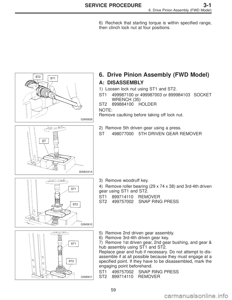
G3M0628
6. Drive Pinion Assembly (FWD Model)
A: DISASSEMBLY
1) Loosen lock nut using ST1 and ST2.
ST1 499987100 or 499987003 or 899984103 SOCKET
WRENCH (35)
ST2 899884100 HOLDER
NOTE:
Remove caulking before taking off lock nut.
B3M0341A
2) Remove 5th driven gear using a press.
ST 498077000 5TH DRIVEN GEAR REMOVER
G3M0610
3) Remove woodruff key.
4) Remove roller bearing (29 x 74 x 38) and 3rd-4th driven
gear using ST1 and ST2.
ST1 899714110 REMOVER
ST2 499757002 SNAP RING PRESS
G3M0611
5) Remove 2nd driven gear assembly.
6) Remove 3rd-4th driven gear key.
7) Remove 1st driven gear, 2nd gear bushing, and gear &
hub assembly using ST1 and ST2.
Replace gear and hub if necessary. Do not attempt to dis-
assemble if at all possible because they must engage at a
specified point. If they have to be disassembled, mark the
engaging point beforehand.
ST1 499757002 SNAP RING PRESS
ST2 899714110 REMOVER
59
3-1SERVICE PROCEDURE
6. Drive Pinion Assembly (FWD Model)