Page 352 of 3342
G2M0709
1. General Precautions
1) Before disassembling engine, place it on ST3.
ST1 498457000 ENGINE STAND ADAPTER RH
ST2 498457100 ENGINE STAND ADAPTER LH
ST3 499817000 ENGINE STAND
2) All parts should be thoroughly cleaned, paying special
attention to the engine oil passages, pistons and bearings.
3) Rotating parts and sliding parts such as piston, bearing
and gear should be coated with oil prior to assembly.
4) Be careful not to let oil, grease or coolant contact the
timing belt, clutch disc and flywheel.
5) All removed parts, if to be reused, should be reinstalled
in the original positions and directions.
6) Gaskets and lock washers must be replaced with new
ones. Liquid gasket should be used where specified to
prevent leakage.
7) Bolts, nuts and washers should be replaced with new
ones as required.
8) Even if necessary inspections have been made in
advance, proceed with assembly work while making
rechecks.
11
2-3bSERVICE PROCEDURE
1. General Precautions
Page 381 of 3342
 If the clearance between valve guide and stem exceeds
the specification, replace guide as follows:
(1) Place cylinder head on ST1 with the combustion
chamber upward so that valve guides ent")
G2M0762
2) If the clearance between valve guide and stem exceeds
the specification, replace guide as follows:
(1) Place cylinder head on ST1 with the combustion
chamber upward so that valve guides enter the holes
in ST1.
(2) Insert ST2 into valve guide and press it down to
remove valve guide.
ST1 498267600 CYLINDER HEAD TABLE
ST2 499767200 VALVE GUIDE REMOVER
G2M0763
(3) Turn cylinder head upside down and place ST as
shown in the figure.
ST 498267700 VALVE GUIDE ADJUSTER
G2M0764
(4) Before installing new valve guide, make sure that
neither scratches nor damages exist on the inside sur-
face of the valve guide holes in cylinder head.
(5) Put new valve guide, coated with sufficient oil, in
cylinder, and insert ST1 into valve guide. Press in until
the valve guide upper end is flush with the upper sur-
face of ST2.
ST1 499767200 VALVE GUIDE REMOVER
ST2 498267700 VALVE GUIDE ADJUSTER
(6) Check the valve guide protrusion.
Valve guide protrusion: L
12.0—12.4 mm (0.472—0.488 in)
(7) Ream the inside of valve guide with ST. Gently
rotate the reamer clockwise while pressing it lightly into
valve guide, and return it also rotating clockwise. After
reaming, clean valve guide to remove chips.
ST 499767400 VALVE GUIDE REAMER
CAUTION:
�Apply engine oil to the reamer when reaming.
�If the inner surface of the valve guide is torn, the
edge of the reamer should be slightly ground with an
oil stone.
�If the inner surface of the valve guide becomes lus-
trous and the reamer does not chips, use a new reamer
or remedy the reamer.
(8) Recheck the contact condition between valve and
valve seat after replacing valve guide.
40
2-3bSERVICE PROCEDURE
4. Cylinder Head
Page 383 of 3342
CAUTION:
�Apply engine oil to oil seal before force-fitting.
�Differentiate between intake valve oil seal and
exhaust valve oil seal by noting their difference in
color.
Color of rubber part:
Intake [Black]
Exhaust [Brown]
Color of spring part:
Intake [Black]
Exhaust [Black]
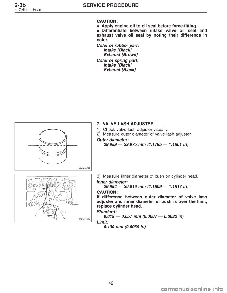
G2M0766
7. VALVE LASH ADJUSTER
1) Check valve lash adjuster visually.
2) Measure outer diameter of valve lash adjuster.
Outer diameter:
29.959—29.975 mm (1.1795—1.1801 in)
G2M0767
3) Measure inner diameter of bush on cylinder head.
Inner diameter:
29.994—30.016 mm (1.1809—1.1817 in)
CAUTION:
If difference between outer diameter of valve lash
adjuster and inner diameter of bush is over the limit,
replace cylinder head.
Standard:
0.019—0.057 mm (0.0007—0.0022 in)
Limit:
0.100 mm (0.0039 in)
42
2-3bSERVICE PROCEDURE
4. Cylinder Head
Page 421 of 3342

2. Engine Noise
Type of sound Condition Possible cause
Regular clicking soundSound increases as engine
speed increases.Valve mechanism is defective.
�Incorrect valve clearance
�Worn camshaft
�Broken valve spring
Heavy and dull clankOil pressure is low.�Worn crankshaft main bearing
�Worn connecting rod bearing (big end)
Oil pressure is normal.�Loose flywheel mounting bolts
�Damaged engine mounting
High-pitched clank
(Spark knock)Sound is noticeable when
accelerating with an overload.�Ignition timing advanced
�Accumulation of carbon inside combustion chamber
�Wrong spark plug
�Improper gasoline
Clank when engine speed is
medium (1,000 to 2,000 rpm).Sound is reduced when fuel
injector connector of noisy
cylinder is disconnected.
(NOTE*)�Worn crankshaft main bearing
�Worn bearing at crankshaft end of connecting rod
Knocking sound when engine
is operating under idling speed
and engine is warm.Sound is reduced when fuel
injector connector of noisy
cylinder is disconnected.
(NOTE*)�Worn cylinder liner and piston ring
�Broken or stuck piston ring
�Worn piston pin and hole at piston end of connecting rod
Sound is not reduced if each
fuel injector connector is
disconnected in turn. (NOTE*)�Unusually worn valve lifter
�Worn camshaft journal bore in crankcase
Squeaky sound—�Insufficient generator lubrication
Rubbing sound—�Defective generator brush and rotor contact
Gear scream when starting
engine—�Defective ignition starter switch
�Worn gear and starter pinion
Sound like polishing glass with
a dry cloth—�Loose drive belt
�Defective engine coolant pump shaft
Hissing sound—�Loss of compression
�Air leakage in air intake system, hoses, connections or
manifolds
Timing belt noise—�Loose timing belt
�Belt contacting case/adjacent part
Valve tappet noise—�Incorrect valve clearance
NOTE*:
When disconnecting fuel injector connector, Malfunction Indicator Light (CHECK ENGINE light) illuminates and trouble code is stored in
ECM memory.
Therefore, carry out the CLEAR MEMORY MODE and INSPECTION MODE after connecting fuel injector connector. (Ref. to 2-7 On-Board
Diagnostics II System.)
80
2-3bDIAGNOSTICS
2. Engine Noise
Page 431 of 3342
G2M0082
15) Separate oil strainer from oil strainer stay.
G2M0376
16) Remove oil strainer.
G2M0377
17) Remove baffle plate and oil strainer stay.
B: INSPECTION
By visual check make sure oil pan, oil strainer, oil strainer
stay and baffle plate are not damaged.
G2M0377
C: INSTALLATION
CAUTION:
Before installing oil pan, clean sealant from oil and
engine block.
1) Install baffle plate and oil strainer stay.
Tightening torque:
5N⋅m (0.5 kg-m, 3.6 ft-lb)
11
2-4SERVICE PROCEDURE
2. Oil Pan and Oil Strainer
Page 438 of 3342
 O")
1. Engine Lubrication System
Before troubleshooting, make sure that the engine oil level
is correct and no oil leakage exists.
Trouble Possible cause Corrective action
1. Warning light remains
on.1) Oil pressure switch
failureCracked diaphragm or oil leakage within switch Replace.
Broken spring or seized contacts Replace.
2) Low oil pressureClogged oil filter Replace.
Malfunction of oil by-pass valve of oil filter Clean or replace.
Malfunction of oil relief valve of oil pump Clean or replace.
Clogged oil passage Clean.
Excessive tip clearance and side clearance of oil
pump rotor and gearReplace.
Clogged oil strainer or broken pipe Clean or replace.
3) No oil pressureInsufficient engine oil Replenish.
Broken pipe of oil strainer Replace.
Stuck oil pump rotor Replace.
2. Warning light does not
go on.1) Burn-out bulb Replace.
2) Poor contact of switch contact points Replace.
3) Disconnection of wiring Repair.
3. Warning light flickers
momentarily.1) Poor contact at terminals Repair.
2) Defective wiring harness Repair.
3) Low oil pressureCheck for the same pos-
sible causes as listed in
1.—2)
17
2-4DIAGNOSTICS
1. Engine Lubrication System
Page 445 of 3342
 Fill engine coolant into reservoir tank up to upper level.
4) Attach radiator cap and reservoir tank cap properly.
5) Install air vent plug.
6) Warm-up engine completely for more than five")
B2M0140
3) Fill engine coolant into reservoir tank up to upper level.
4) Attach radiator cap and reservoir tank cap properly.
5) Install air vent plug.
6) Warm-up engine completely for more than five minutes
at 2,000 to 3,000 rpm.
7) Stop engine and wait until temperature drops to a safe
level.
8) If engine coolant level drops in radiator, add engine
coolant to filler neck position.
9) If engine coolant level drops from upper level of reser-
voir tank, add engine coolant to upper level.
10) Attach radiator cap and reservoir tank cap properly.
B2M0136
C: CHECKING OF COOLING SYSTEM
1) Remove radiator cap, top off radiator, and attach tester
to radiator in place of cap.
2) Apply a pressure of 157 kPa (1.6 kg/cm
2, 23 psi) to
radiator to check if:
(1) Engine coolant leaks at/around radiator.
(2) Engine coolant leaks at/around hoses or connec-
tions.
CAUTION:
�Engine should be off.
�Wipe engine coolant from check points in advance.
�Be careful to prevent engine coolant from spurting
out when removing tester.
�Be careful also not to deform filler neck of radiator
when installing or removing tester.
8
2-5SERVICE PROCEDURE
1. On-Car Service
Page 448 of 3342
G2M0210
12) Remove tensioner bracket.
13) Disconnect heater hose from engine coolant pump.
14) Remove engine coolant pump.
B: INSPECTION
1) Check engine coolant pump bearing for smooth rota-
tion.
2) Check engine coolant pump pulley for abnormalities.
G2M0211
3) Using a dial gauge, measure impeller runout in thrust
direction while rotating the pulley.
“Thrust”runout limit:
0.5 mm (0.020 in)
G2M0212
4) Check clearance between impeller and pump case.
Clearance between impeller and pump case:
Standard
0.5—0.7 mm (0.020—0.028 in)
Limit
1.0 mm (0.039 in)
5) After engine coolant pump installation, check pulley
shaft for engine coolant leaks. If leaks are noted, replace
engine coolant pump assembly.
11
2-5SERVICE PROCEDURE
2. Engine Coolant Pump
 Before disassembling engine, place it on ST3.
ST1 498457000 ENGINE STAND ADAPTER RH
ST2 498457100 ENGINE STAND ADAPTER LH
ST3 499817000 ENGINE STAND
2) All parts shou")
 Separate oil strainer from oil strainer stay.
G2M0376
16) Remove oil strainer.
G2M0377
17) Remove baffle plate and oil strainer stay.
B: INSPECTION
By visual check make sure oil pan, oil s")
 Remove tensioner bracket.
13) Disconnect heater hose from engine coolant pump.
14) Remove engine coolant pump.
B: INSPECTION
1) Check engine coolant pump bearing for smooth rota-
tion.
2)")