Page 178 of 3342
![SUBARU LEGACY 1997 Service Repair Manual
BRAKES
[ABS
5
.3i
TYPE]
[T10AA3]
4-4d
10
.
Diagnostics
Chart
with
Select
Monitor
F49
1
1
2
1
3
1415
1
6
1
7
1
8
9
01112131415
~I61718192
21
23
4
1
2526
1281261301311
LeRVI
B4M1254A
a
1121314151 SUBARU LEGACY 1997 Service Repair Manual
BRAKES
[ABS
5
.3i
TYPE]
[T10AA3]
4-4d
10
.
Diagnostics
Chart
with
Select
Monitor
F49
1
1
2
1
3
1415
1
6
1
7
1
8
9
01112131415
~I61718192
21
23
4
1
2526
1281261301311
LeRVI
B4M1254A
a
1121314151](/manual-img/17/57434/w960_57434-177.png)
BRAKES
[ABS
5
.3i
TYPE]
[T10AA3]
4-4d
10
.
Diagnostics
Chart
with
Select
Monitor
F49
1
1
2
1
3
1415
1
6
1
7
1
8
9
01112131415
~I61718192
21
23
4
1
2526
1281261301311
LeRVI
B4M1254A
a
112131415161718
9l101111121131141151
11611711811912
1_~23
1
242526
728293031
D
n
SL
f
B4M1243A
1
10AA1
I
CHECK
INPUT
VOLTAGE
OF
ABSCM&H/U
.
1)
Turn
ignition
switch
to
OFF
.
2)
Disconnect
connector
from
ABSCM&H/U
.
3)
Run
the
engine
atidle
.
4)
Measure
voltage
between
ABSCM&H/U
connector
and
chassis
ground
.
Connector
&
terminal
(F49)
No
.
1
(+)
-
Chassis
ground
(
)
:
(F49)
No
.
24
(+)
-
Chassis
ground
(-)
:
CHECK
:
Is
thevoltage
between
10
V
and
15
V?
,rES
:
GO
t0
step
10AA2
.
No
:
Repair
harness
connector
between
battery
and
ABSCM&H/U
.
I
10AA2
I
CHECK
GROUND
CIRCUIT
OF
ABSCM&HIU
.
1)
Turn
ignition
switchto
OFF
.
2)
Measure
resistance
between
ABSCM&H/U
connector
and
chassis
ground
.
Connector
&
terminal
(F49)
No
.
23
-
Chassis
ground
:
CHECK
:
Is
the
resistance
less
than
0
.5
SZ?
0
:
Go
to
step
10AA3
.
No
:
Repair
ABSCM&H/U
ground
harness
.
I
10AA3
I
CHECKPOOR
CONTACT
IN
CONNECTORS
.
I
CHECK
:
Is
there
poor
contact
in
connectors
between
generator,
battery
and
ABSCM&HlU?
<
Ref
.
to
FOREWORD
[T3C1]
.*10>
vES
:
Repair
connector
.
No
:
Go
tostep
10AA4
.
167
Page 189 of 3342
![SUBARU LEGACY 1997 Service Repair Manual
4-4d
[TyoAE3l
BRAKES
[ABS
5
.31
TYPE]
10
.
Diagnostics
Chart
withSelect
Monitor
F49
D
P)
V
44-
84M1234A
I
F49
1
1
2
3
1
4
1
5
1
6
1
7
1
89
101112131415
1
16
1
17
1
18
1
19
1
2
01
21
12-
L-12
7
1 SUBARU LEGACY 1997 Service Repair Manual
4-4d
[TyoAE3l
BRAKES
[ABS
5
.31
TYPE]
10
.
Diagnostics
Chart
withSelect
Monitor
F49
D
P)
V
44-
84M1234A
I
F49
1
1
2
3
1
4
1
5
1
6
1
7
1
89
101112131415
1
16
1
17
1
18
1
19
1
2
01
21
12-
L-12
7
1](/manual-img/17/57434/w960_57434-188.png)
4-4d
[TyoAE3l
BRAKES
[ABS
5
.31
TYPE]
10
.
Diagnostics
Chart
withSelect
Monitor
F49
D
P)
V
44-
84M1234A
I
F49
1
1
2
3
1
4
1
5
1
6
1
7
1
89
101112131415
1
16
1
17
1
18
1
19
1
2
01
21
12-
L-12
7
12
8
1
2
00
31
1
2324
2526
1L
B4M
1243A
I10AE3]CHECK
INPUT
VOLTAGE
OF
ABSCM&HIU
.
1)
Run
the
engine
at
idle
.
2)
Measure
voltage
between
ABSCM&H/U
connector
and
chassis
ground
.
Connector
&
terminal
(F49)
No
.
1
(+)
-
Chassis
ground
(
)
:
CHECK
:
Is
thevoltage
between
10
V
and
15
V?
YES
:
Go
to
step
10AE4
.
No
:
Repair
harness
connector
between
battery,igni-
tion
switch
and
ABSCM&H/U
.
1
10AE4
I
CHECK
GROUND
CIRCUIT
OF
ABSCM&H/U
.
1)
Turn
ignition
switch
to
OFF
.
2)
Measure
resistance
between
ABSCM&H/U
connector
and
chassis
ground
.
Connector
&
terminal
(F49)
No
.
23
-
Chassis
ground
:
CHECK
;
Is
the
resistance
less
than
0
.5
fl?
Go
to
step
10AE5
.
No
:
Repair
ABSCM&H/U
ground
harness
.
10AE5
CHECK
MOTOR
OPERATION
.
Operate
the
sequence
control
.
<
Ref
.
to
4-4
[W25D1
]
.
>
NOTE
:
Use
the
diagnosis
connector
to
operate
the
sequence
control
.
CHECK
:
Can
motor
revolution
noise
(buzz)
be
heard
when
carrying
outthe
sequence
control?
,rES
:
Go
to
step
10AE6
.
No
:
Replace
hydraulic
unit
.
180
Page 217 of 3342
WIRING
DIAGRAM
[osoa1
6-3
6
.
Wiring
Diagram
F2
100
Twisted
wire
LL
7
-
---
-
---------
-
FtP1
Transmission
control
module
Check
Data
link
connectorconnector
879
EEE
878
a
B56
:c
Ref
.
to
Engine
electrical
system
.
881
Diagnosis
PEterminal
B82
Q1
-
Diagnosis
connector
Front
~--~~
ABS
sensorLH
II
---------------
------_-----_--_----_J
Twisted
wire
ABS
G
sensor
86
B15
P8
(Outback
model
:
Brown)
O
(Other
models
:
Gray)
(Other
models)
(Outback
model)
(Gray)
86
Front
m--F-I
ABS
sensor
RH
n
(Outback
(Other
(Outback
(Other
model)
models)
model)
models)
RearABS
Rear
ABS
sensor
RH
sensor
LH
------------------
P11
1
01
P-am
B78
(Yellow)
879
(Gray)
F1
856
(Black)
1
4
1
4
56
10131
1
1
12131
45
6
8
10
56
88
99
10
111
1314
45678
1
11
1
12
1
13
1
14
1
15
1
16
11
/1
16
1
19
12U]
B82
(Black)
1
456
8100
(Blue)
4
6
171619
111
1
1415161
18192010BU82-04B
3
Page 246 of 3342

1. Foreword
This chapter describes major inspection and service pro-
cedures for the engine mounted on the body. For proce-
dures not found in this chapter, refer to the service proce-
dure section in the applicable chapter.
2. Ignition Timing
A: MEASUREMENT
1. 2200 cc MODEL
1) Warm-up the engine.
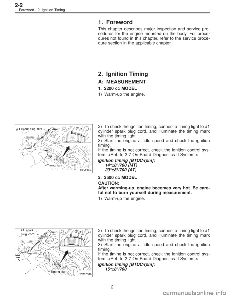
G2M0094
2) To check the ignition timing, connect a timing light to #1
cylinder spark plug cord, and illuminate the timing mark
with the timing light.
3) Start the engine at idle speed and check the ignition
timing.
If the timing is not correct, check the ignition control sys-
tem.
Ignition timing [BTDC/rpm]:
14°±8°/700 (MT)
20°±8°/700 (AT)
2. 2500 cc MODEL
CAUTION:
After warming-up, engine becomes very hot. Be care-
ful not to burn yourself during measurement.
1) Warm-up the engine.
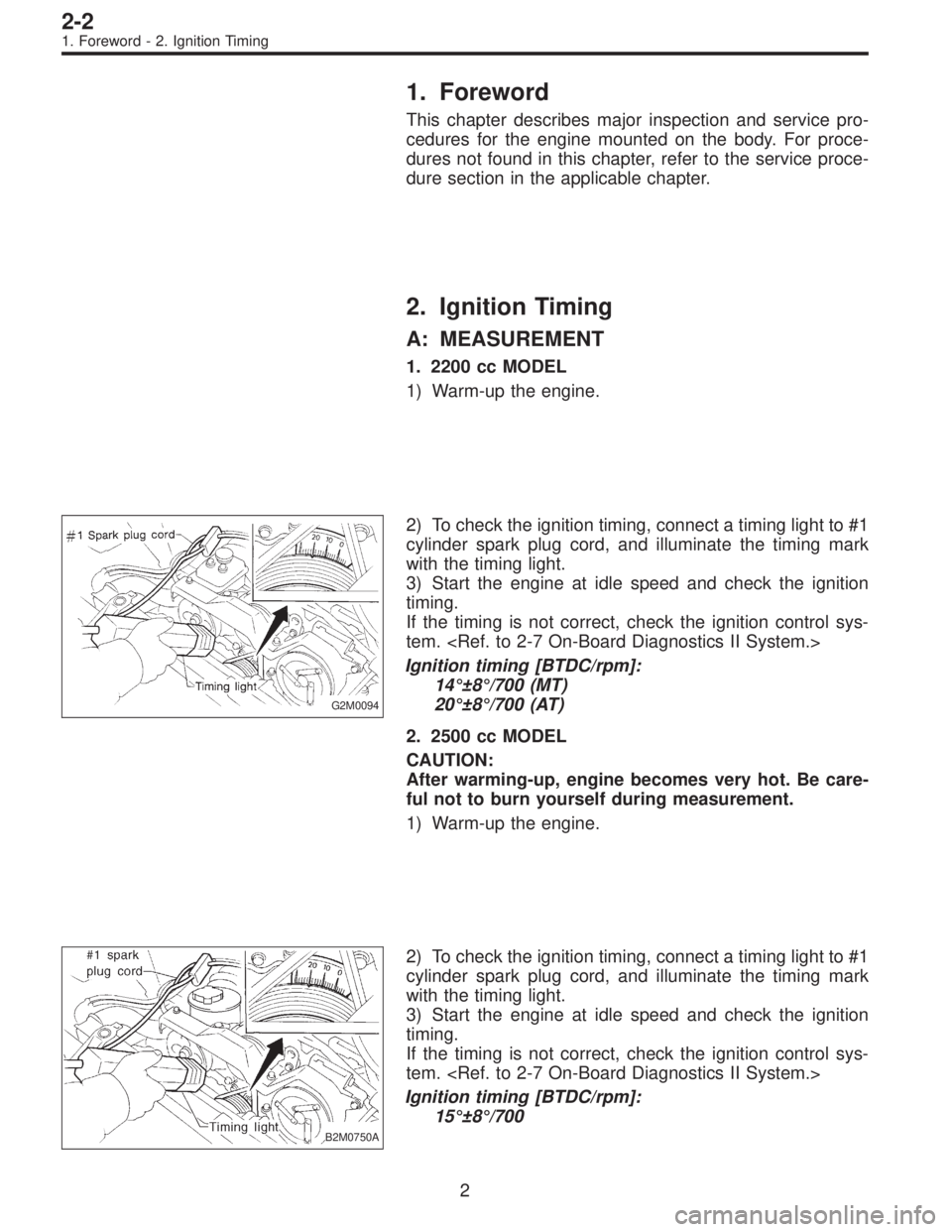
B2M0750A
2) To check the ignition timing, connect a timing light to #1
cylinder spark plug cord, and illuminate the timing mark
with the timing light.
3) Start the engine at idle speed and check the ignition
timing.
If the timing is not correct, check the ignition control sys-
tem.
Ignition timing [BTDC/rpm]:
15°±8°/700
2
2-2
1. Foreword - 2. Ignition Timing
Page 247 of 3342

1. Foreword
This chapter describes major inspection and service pro-
cedures for the engine mounted on the body. For proce-
dures not found in this chapter, refer to the service proce-
dure section in the applicable chapter.
2. Ignition Timing
A: MEASUREMENT
1. 2200 cc MODEL
1) Warm-up the engine.
G2M0094
2) To check the ignition timing, connect a timing light to #1
cylinder spark plug cord, and illuminate the timing mark
with the timing light.
3) Start the engine at idle speed and check the ignition
timing.
If the timing is not correct, check the ignition control sys-
tem.
Ignition timing [BTDC/rpm]:
14°±8°/700 (MT)
20°±8°/700 (AT)
2. 2500 cc MODEL
CAUTION:
After warming-up, engine becomes very hot. Be care-
ful not to burn yourself during measurement.
1) Warm-up the engine.
B2M0750A
2) To check the ignition timing, connect a timing light to #1
cylinder spark plug cord, and illuminate the timing mark
with the timing light.
3) Start the engine at idle speed and check the ignition
timing.
If the timing is not correct, check the ignition control sys-
tem.
Ignition timing [BTDC/rpm]:
15°±8°/700
2
2-2
1. Foreword - 2. Ignition Timing
Page 248 of 3342

3. Engine Idle Speed
A: MEASUREMENT
1) Before checking idle speed, check the following:
(1) Ensure that air cleaner element is free from
clogging, ignition timing is correct, spark plugs are in
good condition, and that hoses are connected properly.
(2) Ensure that malfunction indicator light (CHECK
ENGINE light) does not illuminate.
2) Warm-up the engine.
G2M0096
3) Connect Subaru Select Monitor or the OBD-II general
scan tool to data link connector.
CAUTION:
When connecting Subaru Select Monitor, turn ignition
switch to OFF.
4) Start the engine and measure engine speed.
NOTE:
Engine speed is indicated on Subaru Select Monitor by
selecting “MODE F04”.
G2M0097
NOTE:
�When using the OBD-II general scan tool, carefully read
its operation manual.
�When Subaru Select Monitor is not used, attach the
pickup sensor on tachometer (Secondary pickup type) to
#1 cylinder spark plug cord.
�This ignition system provides simultaneous ignition for
#1 and #2 plugs. It must be noted that some tachometers
may register twice that of actual engine speed.
5) Check idle speed when unloaded. (With headlights,
heater fan, rear defroster, radiator fan, air conditioning, etc.
OFF)
Idle speed (No load and gears in neutral (MT) or N or
P (AT) position):
700±100 rpm
6) Check idle speed when loaded. (Turn air conditioning
switch to “ON” and operate compressor for at least one
minute before measurement.)
Idle speed [A/C“ON”, no load and gears in neutral
(MT) or N or P (AT) position]:
850±50 rpm
CAUTION:
Never rotate idle adjusting screw. If idle speed is out
of specifications, refer to General On-board Diagnosis
Table under “2-7 On-Board Diagnostics II System”.
3
2-2
3. Engine Idle Speed
Page 249 of 3342

4. Engine Compression
A: MEASUREMENT
1. 2200 cc MODEL
1) After warming-up the engine, turn ignition switch to
OFF.
2) Make sure that the battery is fully charged.
3) Remove all the spark plugs.
4) Disconnect connectors from fuel injectors.
5) Fully open throttle valve.
6) Check the starter motor for satisfactory performance
and operation.
G2M0098
7) Hold the compression gauge tight against the spark
plug hole.
CAUTION:
When using a screw-in type compression gauge, the
screw (put into cylinder head spark plug hole) should
be less than 18 mm (0.71 in) long.
8) Crank the engine by means of the starter motor, and
read the maximum value on the gauge when the pointer is
steady.
9) Perform at least two measurements per cylinder, and
make sure that the values are correct.
Compression (200—300 rpm and fully open throttle):
Standard
1,079—1,275 kPa
(11.0—13.0 kg/cm
2, 156—185 psi)
Limit
883 kPa (9.0 kg/cm
2, 128 psi)
Difference between cylinders
196 kPa (2.0 kg/cm
2, 28 psi)
2. 2500 cc MODEL
CAUTION:
After warming-up, engine becomes very hot. Be care-
ful not to burn yourself during measurement.
1) After warming-up the engine, turn ignition switch to
OFF.
2) Make sure that the battery is fully charged.
3) Remove all the spark plugs.
[W3E0].>
4) Disconnect connectors from fuel injectors.
4
2-2
4. Engine Compression
Page 250 of 3342
5) Fully open throttle valve.
6) Check the starter motor for satisfactory performance
and operation.
B2M0752A
7) Hold the compression gauge tight against the spark
plug hole.
CAUTION:
When using a screw-in type compression gauge, the
screw (put into cylinder head spark plug hole) should
be less than 18 mm (0.71 in) long.
8) Crank the engine by means of the starter motor, and
read the maximum value on the gauge when the pointer is
steady.
9) Perform at least two measurements per cylinder, and
make sure that the values are correct.
Compression (350 rpm and fully open throttle):
Standard
1,216 kPa
(12.4 kg/cm
2, 176 psi)
Limit
941 kPa (9.6 kg/cm
2, 137 psi)
Difference between cylinders
49 kPa (0.5 kg/cm
2, 7 psi), or less
5
2-2
4. Engine Compression