Page 2477 of 3342

1. Supplemental Restraint System
“Airbag”
Airbag system wiring harness is routed near the ABS/TCS
control module, ABS sensor and hydraulic control unit.
CAUTION:
�All Airbag system wiring harness and connectors
are colored yellow. Do not use electrical test equip-
ment on these circuit.
�Be careful not to damage Airbag system wiring har-
ness when servicing the ABS/TCS control module,
ABS sensor and hydraulic control unit.
2. Pre-inspection
Before performing diagnostics, check the following items
which might affect ABS/TCS problems:
A: MECHANICAL INSPECTION
1. POWER SUPPLY
1) Measure battery voltage and specific gravity of electro-
lyte.
Standard voltage: 12 V, or more
Specific gravity: Above 1.260
2) Check the condition of the main and other fuses, and
harnesses and connectors. Also check for proper ground-
ing.
2. BRAKE FLUID
1) Check brake fluid level.
2) Check brake fluid leakage.
3. BRAKE DRAG
Check brake drag.
4. BRAKE PAD AND ROTOR
Check brake pad and rotor.
5. TIRE SPECIFICATIONS, TIRE WEAR AND AIR
PRESSURE
Check tire specifications, tire wear and air pressure.
to 4-2 [S1A0].>
2
4-4bBRAKES
1. Supplemental Restraint System“Airbag”- 2. Pre-inspection
Page 2478 of 3342

1. Supplemental Restraint System
“Airbag”
Airbag system wiring harness is routed near the ABS/TCS
control module, ABS sensor and hydraulic control unit.
CAUTION:
�All Airbag system wiring harness and connectors
are colored yellow. Do not use electrical test equip-
ment on these circuit.
�Be careful not to damage Airbag system wiring har-
ness when servicing the ABS/TCS control module,
ABS sensor and hydraulic control unit.
2. Pre-inspection
Before performing diagnostics, check the following items
which might affect ABS/TCS problems:
A: MECHANICAL INSPECTION
1. POWER SUPPLY
1) Measure battery voltage and specific gravity of electro-
lyte.
Standard voltage: 12 V, or more
Specific gravity: Above 1.260
2) Check the condition of the main and other fuses, and
harnesses and connectors. Also check for proper ground-
ing.
2. BRAKE FLUID
1) Check brake fluid level.
2) Check brake fluid leakage.
3. BRAKE DRAG
Check brake drag.
4. BRAKE PAD AND ROTOR
Check brake pad and rotor.
5. TIRE SPECIFICATIONS, TIRE WEAR AND AIR
PRESSURE
Check tire specifications, tire wear and air pressure.
to 4-2 [S1A0].>
2
4-4bBRAKES
1. Supplemental Restraint System“Airbag”- 2. Pre-inspection
Page 2484 of 3342
P6 14—GNDLess than 0.7 V whe")
Contents Connector No. Terminal No.Input/Output signals
Measured value and measuring conditions
TCS
control
unit ECM
commun-
icationTCS,ECM communication
(torque command)P6 14—GNDLess than 0.7 V when the vehicle stands
still.
TCS,ECM communication
(torque command)P6 5—GNDLess than 5 V when the vehicle stands
still.
TCS,ECM communication
(TCS operates)P6 12—GND4—5.4 V when TCS controls no
operations. Less than 0.7 V when it
controls operations.
ECM,TCS communication
(engine control)P6 4—GNDH/L toggle signal with the accelerator
pedal off (Cycle 20 mS, H: 10—14 V, L:
less than 0.7 V). Less than 2.0 V with the
accelerator pedal depressed. Also when
TCS OFF indicator light comes on by TCS
OFF switch.
ABS operation signal P6 13—GND10—14 V when the ABS control does not
operate still and less than 0.7 V when
ABS operates.
Fluid level sensor P7 20—GNDLess than2VwhenIGNisONand10—
14 V when idling.
Select
monitorData is received. P7 9—GND 4—4.5 V when no data is received.
Data is sent. P7 19—GND 4—4.5 V when no data is sent.
Diagnosis connector P7 8—GND 10—14 V when IGN is ON.
Power
supplyIgnition P5 1—GND 10—14 V when IGN is ON.
Battery P5 4—GND 10—14 V
Grounding
linePower P5 5—body 1Ωor less
Digital P7 15—body 1Ωor less
Power P4 6—body 1Ωor less
8
4-4bBRAKES
5. Control Module I/O Signal
Page 2529 of 3342
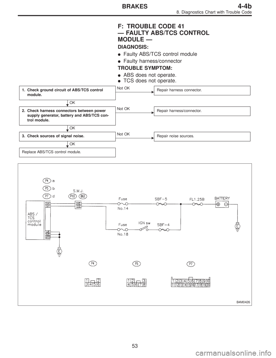
F: TROUBLE CODE 41
—FAULTY ABS/TCS CONTROL
MODULE—
DIAGNOSIS:
�Faulty ABS/TCS control module
�Faulty harness/connector
TROUBLE SYMPTOM:
�ABS does not operate.
�TCS does not operate.
1. Check ground circuit of ABS/TCS control
module.
OK
�Not OK
Repair harness connector.
2. Check harness connectors between power
supply generator, battery and ABS/TCS con-
trol module.
OK
�Not OK
Repair harness/connector.
3. Check sources of signal noise.
OK
�Not OK
Repair noise sources.
Replace ABS/TCS control module.
B4M0426
�
�
�
53
4-4bBRAKES
8. Diagnostics Chart with Trouble Code
Page 2530 of 3342
B4M0405A
1. CHECK GROUND CIRCUIT OF ABS/TCS CONTROL
MODULE.
1) Turn ignition switch OFF.
2) Disconnect connector from ABS/TCS control module.
3) Measure resistance between ABS/TCS control module
connector and body.
Connector & terminal / Specified resistance:
(P4) No. 6—body / 1Ωor less
(P5) No. 5—body / 1Ωor less
(P7) No. 15—body / 1Ωor less
2. CHECK HARNESS CONNECTORS BETWEEN
POWER SUPPLY GENERATOR, BATTERY AND ABS/
TCS CONTROL MODULE.
Check for poor contacts in plug-in connectors. Refer to
“Basic checks”in“FOREWORD”.
54
4-4bBRAKES
8. Diagnostics Chart with Trouble Code
Page 2531 of 3342
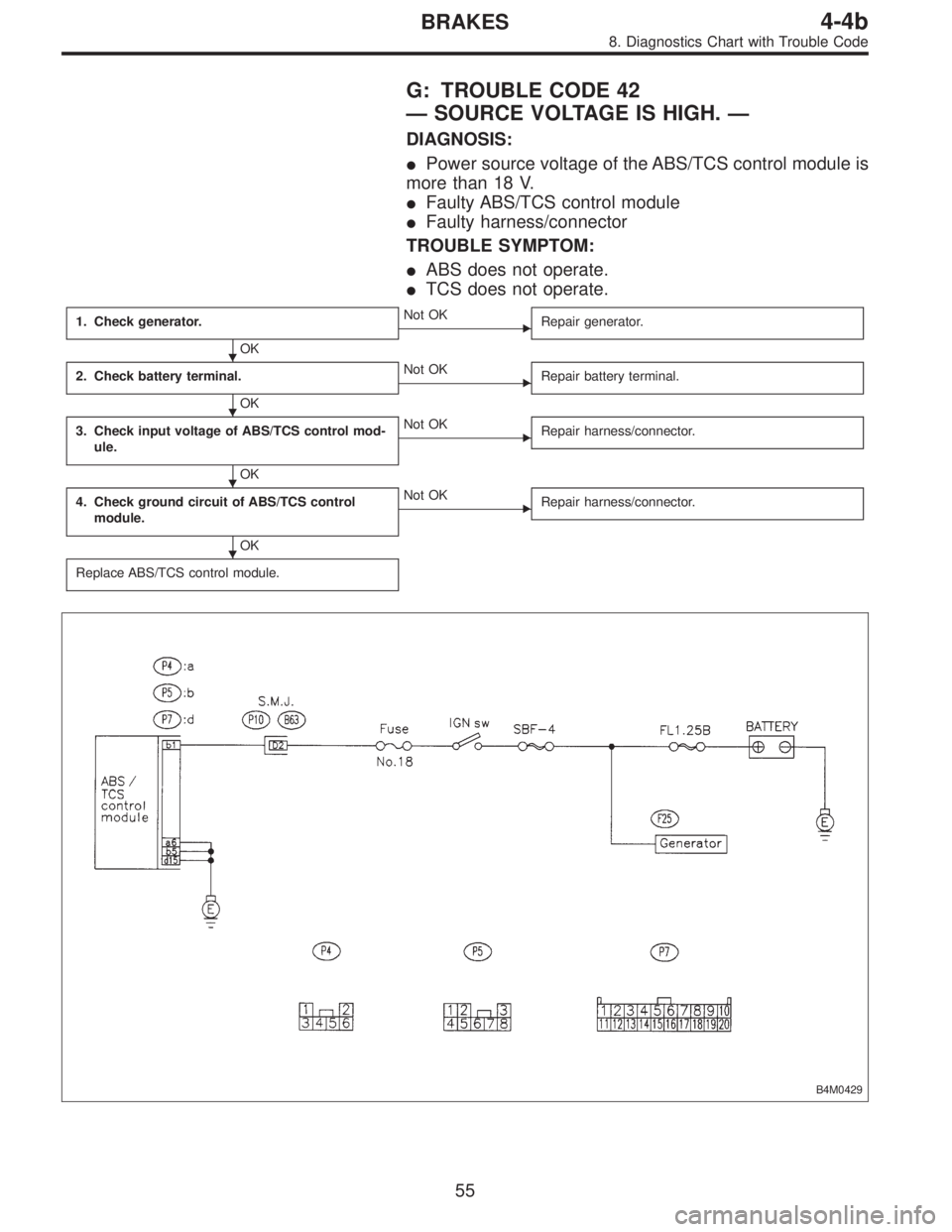
G: TROUBLE CODE 42
—SOURCE VOLTAGE IS HIGH.—
DIAGNOSIS:
�Power source voltage of the ABS/TCS control module is
more than 18 V.
�Faulty ABS/TCS control module
�Faulty harness/connector
TROUBLE SYMPTOM:
�ABS does not operate.
�TCS does not operate.
1. Check generator.
OK
�Not OK
Repair generator.
2. Check battery terminal.
OK
�Not OK
Repair battery terminal.
3. Check input voltage of ABS/TCS control mod-
ule.
OK
�Not OK
Repair harness/connector.
4. Check ground circuit of ABS/TCS control
module.
OK
�Not OK
Repair harness/connector.
Replace ABS/TCS control module.
B4M0429
�
�
�
�
55
4-4bBRAKES
8. Diagnostics Chart with Trouble Code
Page 2532 of 3342
B4M0430
1. CHECK GENERATOR.
1) Idling after warm-up.
2) Measure voltage between generator B terminal and
body.
Connector / Specified voltage:
(F25)—body / 10—15 V
2. CHECK BATTERY TERMINAL.
Check that the positive and negative battery terminals are
firmly fixed.
B4M0431A
3. CHECK INPUT VOLTAGE OF ABS/TCS CONTROL
MODULE.
1) Turn ignition switch OFF.
2) Disconnect connector from ABS/TCS control module.
3) Run the engine at idle.
4) Measure voltage between ABS/TCS control module
connector and body.
Connector & terminal / Specified voltage:
(P5) No. 1—body / 10—15 V
B4M0405A
4. CHECK GROUND CIRCUIT OF ABS/TCS CONTROL
MODULE.
1) Turn ignition switch OFF.
2) Disconnect connector from ABS/TCS control module.
3) Measure resistance between ABS/TCS control module
connector and body.
Connector & terminal / Specified resistance:
(P4) No. 6—body / 1Ωor less
(P5) No. 5—body / 1Ωor less
(P7) No. 15—body / 1Ωor less
56
4-4bBRAKES
8. Diagnostics Chart with Trouble Code
Page 2587 of 3342

B4M0518
S: TROUBLE CODE 38
RL.OUT VALVE
—Faulty rear left outlet solenoid valve—
DIAGNOSIS:
�Faulty harness/connector
�Faulty solenoid valve in hydraulic unit
�Faulty ABS/TCS control module
TROUBLE SYMPTOM:
�ABS and TCS do not operate.
�ABS sequence control does not operate.
�TCS sequence control does not operate.
�Air bleeding mode does not operate.
NOTE:
The procedures used are the same as those for FR.OUT
VA LV E .
B4M0519
T: TROUBLE CODE 41
ECU
—Faulty ABS/TCS control module—
DIAGNOSIS:
�Faulty ABS/TCS control module
�Faulty harness/connector
TROUBLE SYMPTOM:
�ABS does not operate.
�TCS does not operate.
1. Check ground circuit of ABS/TCS control
module.
OK
�Not OK
Repair harness/connector.
2. Check harness connectors between power
supply generator, battery and ABS/TCS con-
trol module.
OK
�Not OK
Repair harness/connector.
3. Check sources of signal noise.
OK
�Not OK
Repair noise sources.
Replace ABS/TCS control module.
�
�
�
111
4-4bBRAKES
10. Diagnostic Chart with Select Monitor
 Turn ignition switch OFF.
2) Disconnect connector from ABS/TCS control module.
3) Measure resistance between ABS/TCS control module
conne")
 Idling after warm-up.
2) Measure voltage between generator B terminal and
body.
Connector / Specified voltage:
(F25)—body / 10—15 V
2. CHECK BATTERY TERMINAL.
Check")