Page 2627 of 3342
B4M0798A
B4M0811A
7B8
CHECK VALVE RELAY.
1) Measure resistance between valve relay terminal and
terminal.
: Terminals
No. 30—No. 87:
Is resistance more than 1 MΩ?
No. 30—No. 87a:
Is resistance less than 0.5Ω?
: Go to next step.
: Replace valve relay.
2) Connect battery to valve relay terminal No. 85 and No.
86.
3) Measure resistance between valve relay terminals.
: Terminals
No. 30—No. 87:
Is resistance less than 0.5Ω?
No. 30—No. 87a:
Is resistance more than 1 MΩ?
: Go to step7B9.
: Replace valve relay.
7B9
CHECK HYDRAULIC CONTROL UNIT.
1) Turn ignition switch to OFF.
2) Connect connector (ABS1) to hydraulic control unit.
3) Turn ignition switch to ON.
: Is the ABS warning light off?
: Go to step7B10.
: Replace hydraulic control unit and check fuse No.
19.
22
4-4cBRAKES [ABS 5.3 TYPE]
7. Diagnostics Chart for ABS Warning Light Circuit and Diagnosis Circuit Failure
Page 2633 of 3342
B: TROUBLE CODE 21 (FRONT RH)
TROUBLE CODE 23 (FRONT LH)
TROUBLE CODE 25 (REAR RH)
TROUBLE CODE 27 (REAR LH)
—ABNORMAL ABS SENSOR (OPEN CIRCUIT
OR INPUT VOLTAGE TOO HIGH)—
DIAGNOSIS:
�Faulty ABS sensor (Broken wire, input voltage too high)
�Faulty harness connector
TROUBLE SYMPTOM:
�ABS does not operate.
8B1.Check resistance of ABS sensor.
8B2.Check battery short of ABS sensor.
8B3.Check harness connector between ABSCM
and ABS sensor.
8B4.Check battery short of harness.
8B5.Check ABS sensor mechanical trouble.
8B6.Check poor contact in connector between
ABSCM and ABS sensor.
8B7.Check ABSCM.
�
�
�
�
�
�
28
4-4cBRAKES [ABS 5.3 TYPE]
8. Diagnostics Chart with Trouble Code
Page 2635 of 3342

B4M0806B
B4M1036A
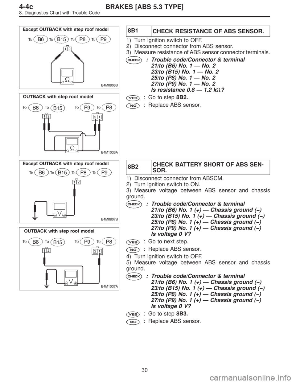
8B1
CHECK RESISTANCE OF ABS SENSOR.
1) Turn ignition switch to OFF.
2) Disconnect connector from ABS sensor.
3) Measure resistance of ABS sensor connector terminals.
: Trouble code/Connector & terminal
21/to (B6) No. 1—No. 2
23/to (B15) No. 1—No. 2
25/to (P8) No. 1—No. 2
27/to (P9) No. 1—No. 2
Is resistance 0.8—1.2 kΩ?
: Go to step8B2.
: Replace ABS sensor.
B4M0807B
B4M1037A
8B2CHECK BATTERY SHORT OF ABS SEN-
SOR.
1) Disconnect connector from ABSCM.
2) Turn ignition switch to ON.
3) Measure voltage between ABS sensor and chassis
ground.
: Trouble code/Connector & terminal
21/to (B6) No. 1 (+)—Chassis ground (�)
23/to (B15) No. 1 (+)—Chassis ground (�)
25/to (P8) No. 1 (+)—Chassis ground (�)
27/to (P9) No. 1 (+)—Chassis ground (�)
Is voltage 0 V?
: Go to next step.
: Replace ABS sensor.
4) Turn ignition switch to OFF.
5) Measure voltage between ABS sensor and chassis
ground.
: Trouble code/Connector & terminal
21/to (B6) No. 1 (+)—Chassis ground (�)
23/to (B15) No. 1 (+)—Chassis ground (�)
25/to (P8) No. 1 (+)—Chassis ground (�)
27/to (P9) No. 1 (+)—Chassis ground (�)
Is voltage 0 V?
: Go to step8B3.
: Replace ABS sensor.
30
4-4cBRAKES [ABS 5.3 TYPE]
8. Diagnostics Chart with Trouble Code
Page 2636 of 3342

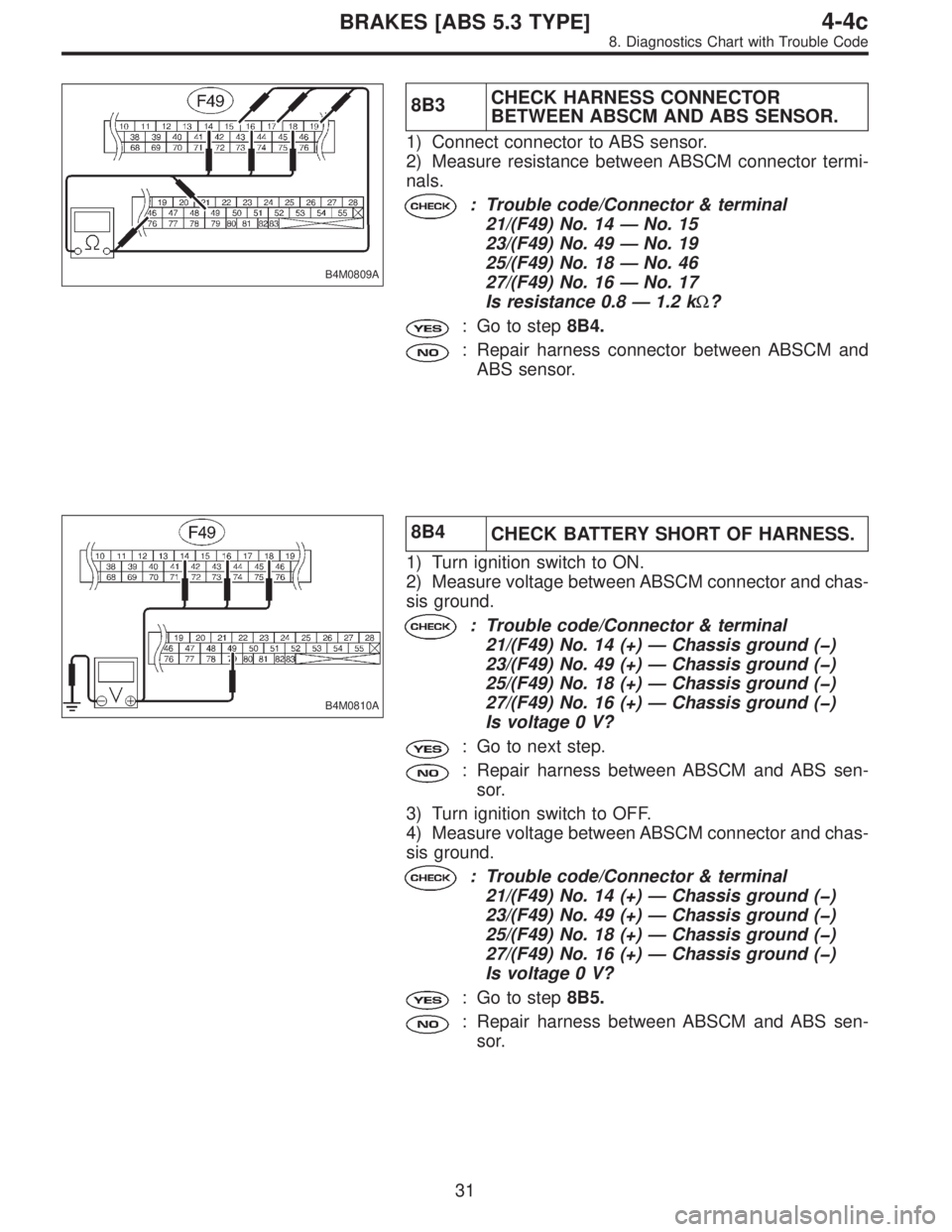
B4M0809A
8B3CHECK HARNESS CONNECTOR
BETWEEN ABSCM AND ABS SENSOR.
1) Connect connector to ABS sensor.
2) Measure resistance between ABSCM connector termi-
nals.
: Trouble code/Connector & terminal
21/(F49) No. 14—No. 15
23/(F49) No. 49—No. 19
25/(F49) No. 18—No. 46
27/(F49) No. 16—No. 17
Is resistance 0.8—1.2 kΩ?
: Go to step8B4.
: Repair harness connector between ABSCM and
ABS sensor.
B4M0810A
8B4
CHECK BATTERY SHORT OF HARNESS.
1) Turn ignition switch to ON.
2) Measure voltage between ABSCM connector and chas-
sis ground.
: Trouble code/Connector & terminal
21/(F49) No. 14 (+)—Chassis ground (�)
23/(F49) No. 49 (+)—Chassis ground (�)
25/(F49) No. 18 (+)—Chassis ground (�)
27/(F49) No. 16 (+)—Chassis ground (�)
Is voltage 0 V?
: Go to next step.
: Repair harness between ABSCM and ABS sen-
sor.
3) Turn ignition switch to OFF.
4) Measure voltage between ABSCM connector and chas-
sis ground.
: Trouble code/Connector & terminal
21/(F49) No. 14 (+)—Chassis ground (�)
23/(F49) No. 49 (+)—Chassis ground (�)
25/(F49) No. 18 (+)—Chassis ground (�)
27/(F49) No. 16 (+)—Chassis ground (�)
Is voltage 0 V?
: Go to step8B5.
: Repair harness between ABSCM and ABS sen-
sor.
31
4-4cBRAKES [ABS 5.3 TYPE]
8. Diagnostics Chart with Trouble Code
Page 2652 of 3342
E: TROUBLE CODE 31 (FRONT RH)
TROUBLE CODE 33 (FRONT LH)
TROUBLE CODE 35 (REAR RH)
TROUBLE CODE 37 (REAR LH)
—ABNORMAL INLET SOLENOID VALVE
CIRCUIT(S) IN HYDRAULIC UNIT—
DIAGNOSIS:
�Faulty harness/connector
�Faulty inlet solenoid valve in hydraulic unit
TROUBLE SYMPTOM:
�ABS does not operate.
8E1.Check resistance of solenoid valve.
8E2.Check ground short of solenoid valve.
8E3.Check battery short of solenoid valve.
8E4.Check battery short of harness.
8E5.Check ground short of harness.
8E6.Check harness connector between ABSCM
and hydraulic unit.
8E7.Check poor contact in connector between
ABSCM and hydraulic unit.
8E8.Check ABSCM.
�
�
�
�
�
�
�
47
4-4cBRAKES [ABS 5.3 TYPE]
8. Diagnostics Chart with Trouble Code
Page 2655 of 3342

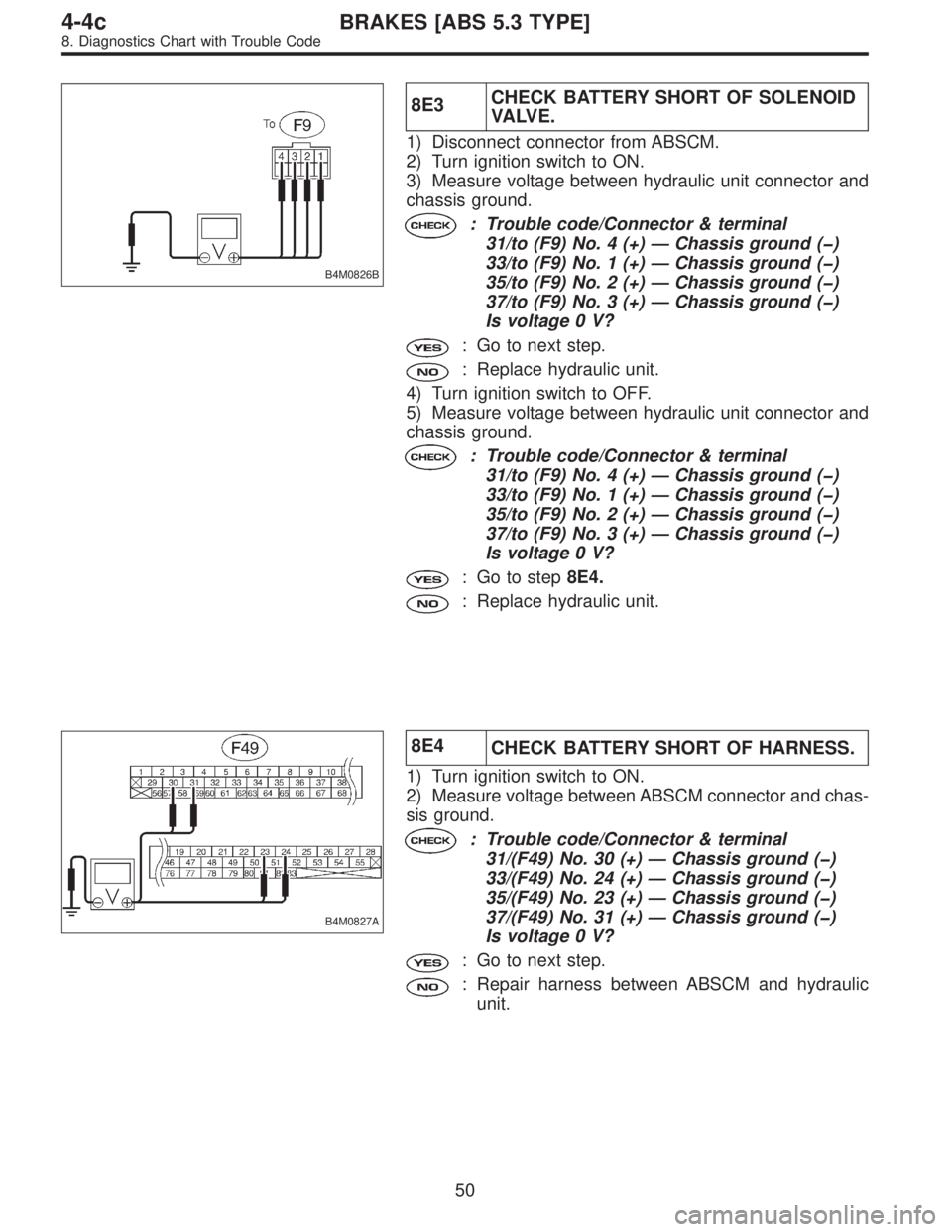
B4M0826B
8E3CHECK BATTERY SHORT OF SOLENOID
VA LV E .
1) Disconnect connector from ABSCM.
2) Turn ignition switch to ON.
3) Measure voltage between hydraulic unit connector and
chassis ground.
: Trouble code/Connector & terminal
31/to (F9) No. 4 (+)—Chassis ground (�)
33/to (F9) No. 1 (+)—Chassis ground (�)
35/to (F9) No. 2 (+)—Chassis ground (�)
37/to (F9) No. 3 (+)—Chassis ground (�)
Is voltage 0 V?
: Go to next step.
: Replace hydraulic unit.
4) Turn ignition switch to OFF.
5) Measure voltage between hydraulic unit connector and
chassis ground.
: Trouble code/Connector & terminal
31/to (F9) No. 4 (+)—Chassis ground (�)
33/to (F9) No. 1 (+)—Chassis ground (�)
35/to (F9) No. 2 (+)—Chassis ground (�)
37/to (F9) No. 3 (+)—Chassis ground (�)
Is voltage 0 V?
: Go to step8E4.
: Replace hydraulic unit.
B4M0827A
8E4
CHECK BATTERY SHORT OF HARNESS.
1) Turn ignition switch to ON.
2) Measure voltage between ABSCM connector and chas-
sis ground.
: Trouble code/Connector & terminal
31/(F49) No. 30 (+)—Chassis ground (�)
33/(F49) No. 24 (+)—Chassis ground (�)
35/(F49) No. 23 (+)—Chassis ground (�)
37/(F49) No. 31 (+)—Chassis ground (�)
Is voltage 0 V?
: Go to next step.
: Repair harness between ABSCM and hydraulic
unit.
50
4-4cBRAKES [ABS 5.3 TYPE]
8. Diagnostics Chart with Trouble Code
Page 2658 of 3342
F: TROUBLE CODE 32 (FRONT RH)
TROUBLE CODE 34 (FRONT LH)
TROUBLE CODE 36 (REAR RH)
TROUBLE CODE 38 (REAR LH)
—ABNORMAL OUTLET SOLENOID VALVE
CIRCUIT(S) IN HYDRAULIC UNIT—
DIAGNOSIS:
�Faulty harness/connector
�Faulty outlet solenoid valve in hydraulic unit
TROUBLE SYMPTOM:
�ABS does not operate.
8F1.Check resistance of solenoid valve.
8F2.Check ground short of solenoid valve.
8F3.Check battery short of solenoid valve.
8F4.Check battery short of harness.
8F5.Check ground short of harness.
8F6.Check harness connector between ABSCM
and hydraulic unit.
8F7.Check poor contact in connector between
ABSCM and hydraulic unit.
8F8.Check ABSCM.
�
�
�
�
�
�
�
53
4-4cBRAKES [ABS 5.3 TYPE]
8. Diagnostics Chart with Trouble Code
Page 2661 of 3342

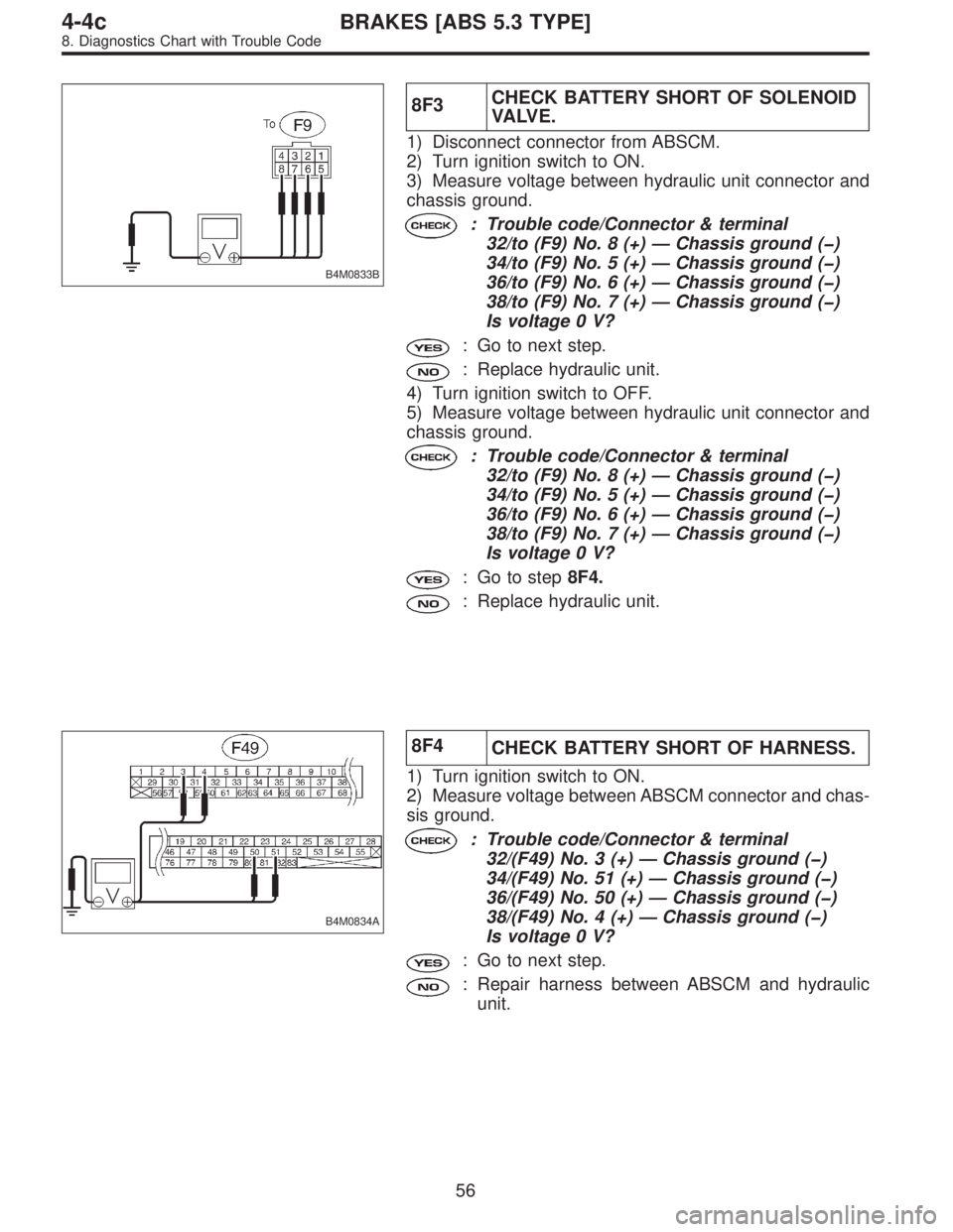
B4M0833B
8F3CHECK BATTERY SHORT OF SOLENOID
VA LV E .
1) Disconnect connector from ABSCM.
2) Turn ignition switch to ON.
3) Measure voltage between hydraulic unit connector and
chassis ground.
: Trouble code/Connector & terminal
32/to (F9) No. 8 (+)—Chassis ground (�)
34/to (F9) No. 5 (+)—Chassis ground (�)
36/to (F9) No. 6 (+)—Chassis ground (�)
38/to (F9) No. 7 (+)—Chassis ground (�)
Is voltage 0 V?
: Go to next step.
: Replace hydraulic unit.
4) Turn ignition switch to OFF.
5) Measure voltage between hydraulic unit connector and
chassis ground.
: Trouble code/Connector & terminal
32/to (F9) No. 8 (+)—Chassis ground (�)
34/to (F9) No. 5 (+)—Chassis ground (�)
36/to (F9) No. 6 (+)—Chassis ground (�)
38/to (F9) No. 7 (+)—Chassis ground (�)
Is voltage 0 V?
: Go to step8F4.
: Replace hydraulic unit.
B4M0834A
8F4
CHECK BATTERY SHORT OF HARNESS.
1) Turn ignition switch to ON.
2) Measure voltage between ABSCM connector and chas-
sis ground.
: Trouble code/Connector & terminal
32/(F49) No. 3 (+)—Chassis ground (�)
34/(F49) No. 51 (+)—Chassis ground (�)
36/(F49) No. 50 (+)—Chassis ground (�)
38/(F49) No. 4 (+)—Chassis ground (�)
Is voltage 0 V?
: Go to next step.
: Repair harness between ABSCM and hydraulic
unit.
56
4-4cBRAKES [ABS 5.3 TYPE]
8. Diagnostics Chart with Trouble Code