Page 515 of 3342
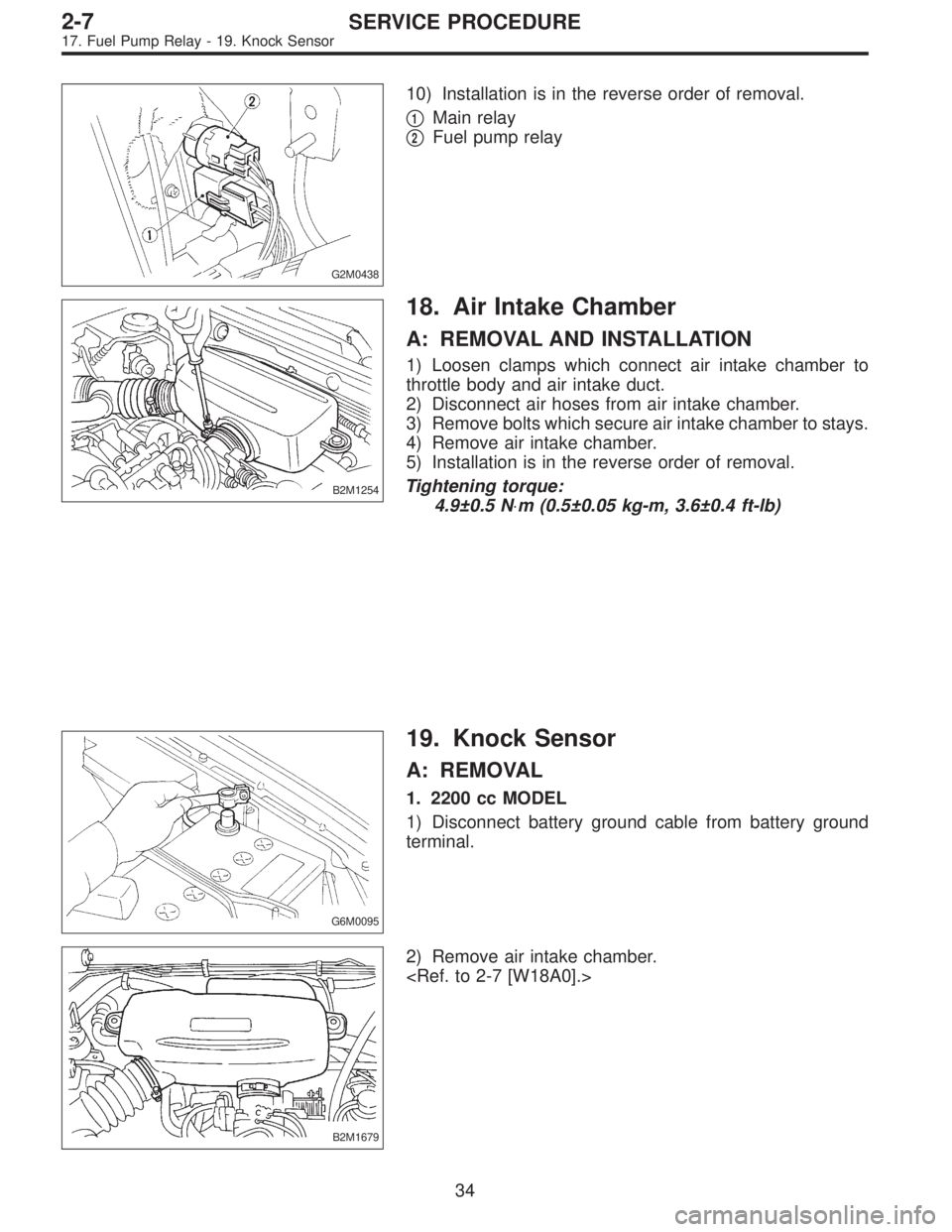
G2M0438
10) Installation is in the reverse order of removal.
�
1Main relay
�
2Fuel pump relay
B2M1254
18. Air Intake Chamber
A: REMOVAL AND INSTALLATION
1) Loosen clamps which connect air intake chamber to
throttle body and air intake duct.
2) Disconnect air hoses from air intake chamber.
3) Remove bolts which secure air intake chamber to stays.
4) Remove air intake chamber.
5) Installation is in the reverse order of removal.
Tightening torque:
4.9±0.5 N⋅m (0.5±0.05 kg-m, 3.6±0.4 ft-lb)
G6M0095
19. Knock Sensor
A: REMOVAL
1. 2200 cc MODEL
1) Disconnect battery ground cable from battery ground
terminal.
B2M1679
2) Remove air intake chamber.
34
2-7SERVICE PROCEDURE
17. Fuel Pump Relay - 19. Knock Sensor
Page 516 of 3342
G2M0438
10) Installation is in the reverse order of removal.
�
1Main relay
�
2Fuel pump relay
B2M1254
18. Air Intake Chamber
A: REMOVAL AND INSTALLATION
1) Loosen clamps which connect air intake chamber to
throttle body and air intake duct.
2) Disconnect air hoses from air intake chamber.
3) Remove bolts which secure air intake chamber to stays.
4) Remove air intake chamber.
5) Installation is in the reverse order of removal.
Tightening torque:
4.9±0.5 N⋅m (0.5±0.05 kg-m, 3.6±0.4 ft-lb)
G6M0095
19. Knock Sensor
A: REMOVAL
1. 2200 cc MODEL
1) Disconnect battery ground cable from battery ground
terminal.
B2M1679
2) Remove air intake chamber.
34
2-7SERVICE PROCEDURE
17. Fuel Pump Relay - 19. Knock Sensor
Page 522 of 3342
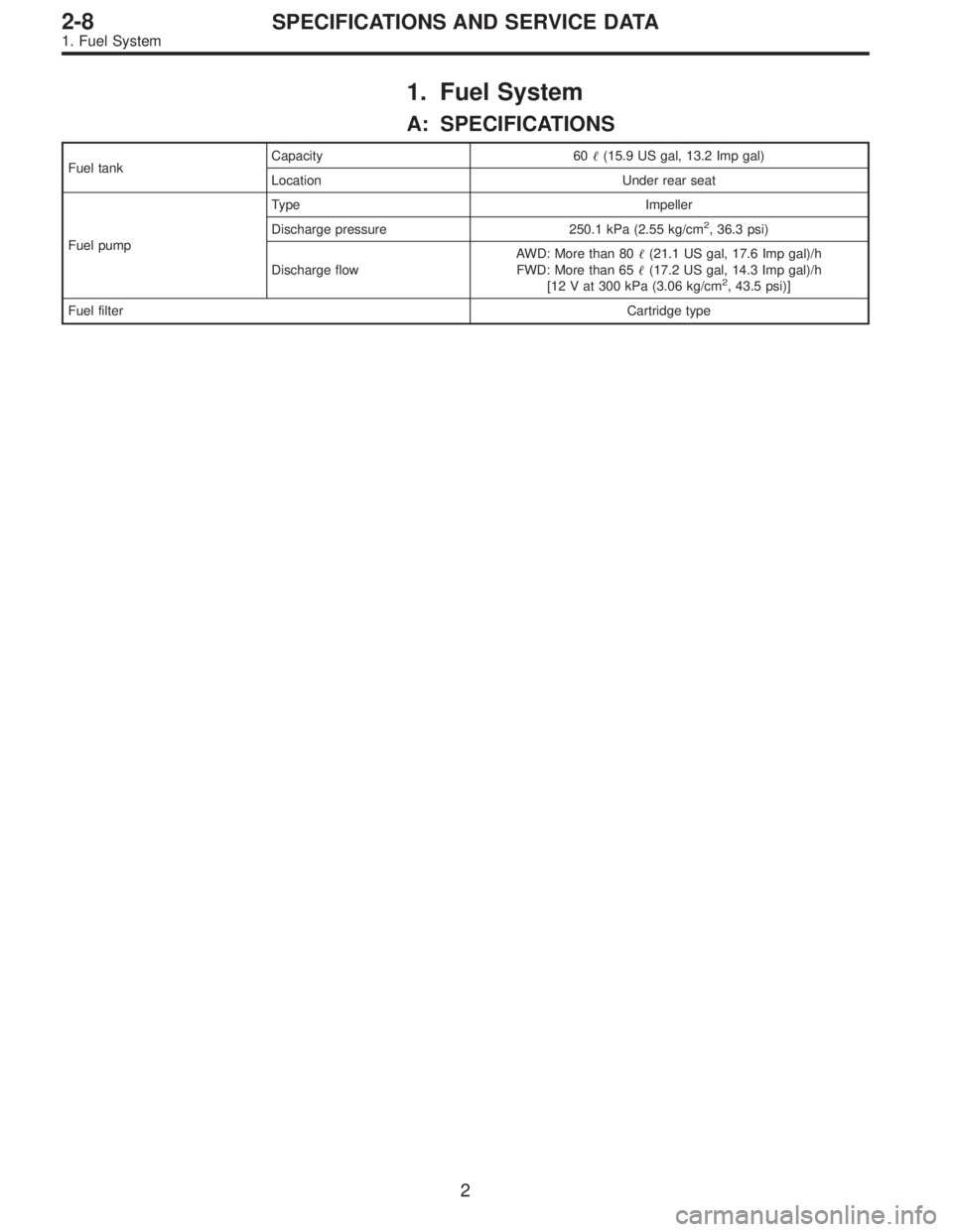
1. Fuel System
A: SPECIFICATIONS
Fuel tankCapacity 60�(15.9 US gal, 13.2 Imp gal)
Location Under rear seat
Fuel pumpType Impeller
Discharge pressure 250.1 kPa (2.55 kg/cm
2, 36.3 psi)
Discharge flowAWD: More than 80�(21.1 US gal, 17.6 Imp gal)/h
FWD: More than 65�(17.2 US gal, 14.3 Imp gal)/h
[12 V at 300 kPa (3.06 kg/cm
2, 43.5 psi)]
Fuel filterCartridge type
2
2-8SPECIFICATIONS AND SERVICE DATA
1. Fuel System
Page 523 of 3342
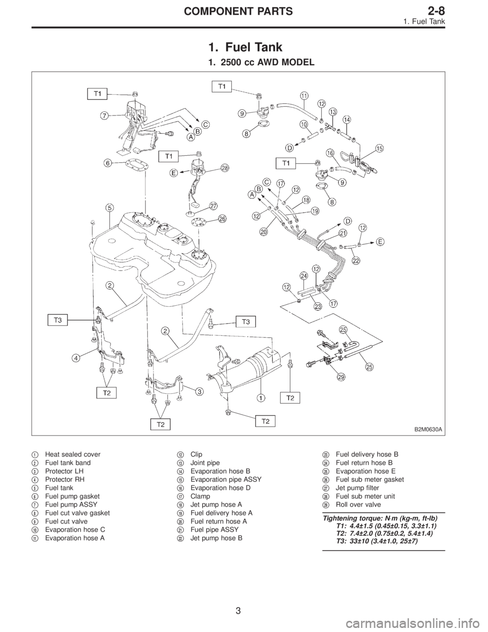
1. Fuel Tank
1. 2500 cc AWD MODEL
B2M0630A
�1Heat sealed cover
�
2Fuel tank band
�
3Protector LH
�
4Protector RH
�
5Fuel tank
�
6Fuel pump gasket
�
7Fuel pump ASSY
�
8Fuel cut valve gasket
�
9Fuel cut valve
�
10Evaporation hose C
�
11Evaporation hose A�
12Clip
�
13Joint pipe
�
14Evaporation hose B
�
15Evaporation pipe ASSY
�
16Evaporation hose D
�
17Clamp
�
18Jet pump hose A
�
19Fuel delivery hose A
�
20Fuel return hose A
�
21Fuel pipe ASSY
�
22Jet pump hose B�
23Fuel delivery hose B
�
24Fuel return hose B
�
25Evaporation hose E
�
26Fuel sub meter gasket
�
27Jet pump filter
�
28Fuel sub meter unit
�
29Roll over valve
Tightening torque: N⋅m (kg-m, ft-lb)
T1: 4.4±1.5 (0.45±0.15, 3.3±1.1)
T2: 7.4±2.0 (0.75±0.2, 5.4±1.4)
T3: 33±10 (3.4±1.0, 25±7)
3
2-8COMPONENT PARTS
1. Fuel Tank
Page 524 of 3342
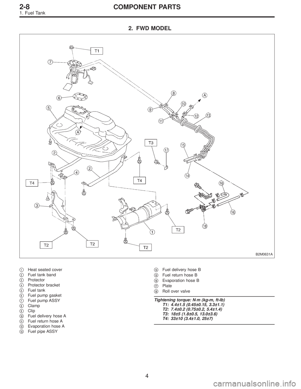
2. FWD MODEL
B2M0631A
�1Heat seated cover
�
2Fuel tank band
�
3Protector
�
4Protector bracket
�
5Fuel tank
�
6Fuel pump gasket
�
7Fuel pump ASSY
�
8Clamp
�
9Clip
�
10Fuel delivery hose A
�
11Fuel return hose A
�
12Evaporation hose A
�
13Fuel pipe ASSY�
14Fuel delivery hose B
�
15Fuel return hose B
�
16Evaporation hose B
�
17Plate
�
18Roll over valve
Tightening torque: N⋅m (kg-m, ft-lb)
T1: 4.4±1.5 (0.45±0.15, 3.3±1.1)
T2: 7.4±0.2 (0.75±0.2, 5.4±1.4)
T3: 18±5 (1.8±0.5, 13.0±3.6)
T4: 33±10 (3.4±1.0, 25±7)
4
2-8COMPONENT PARTS
1. Fuel Tank
Page 526 of 3342
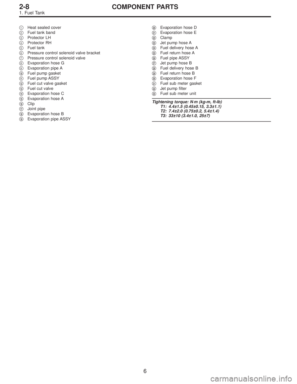
�1Heat sealed cover
�
2Fuel tank band
�
3Protector LH
�
4Protector RH
�
5Fuel tank
�
6Pressure control solenoid valve bracket
�
7Pressure control solenoid valve
�
8Evaporation hose G
�
9Evaporation pipe A
�
10Fuel pump gasket
�
11Fuel pump ASSY
�
12Fuel cut valve gasket
�
13Fuel cut valve
�
14Evaporation hose C
�
15Evaporation hose A
�
16Clip
�
17Joint pipe
�
18Evaporation hose B
�
19Evaporation pipe ASSY�
20Evaporation hose D
�
21Evaporation hose E
�
22Clamp
�
23Jet pump hose A
�
24Fuel delivery hose A
�
25Fuel return hose A
�
26Fuel pipe ASSY
�
27Jet pump hose B
�
28Fuel delivery hose B
�
29Fuel return hose B
�
30Evaporation hose F
�
31Fuel sub meter gasket
�
32Jet pump filter
�
33Fuel sub meter unit
Tightening torque: N⋅m (kg-m, ft-lb)
T1: 4.4±1.5 (0.45±0.15, 3.3±1.1)
T2: 7.4±2.0 (0.75±0.2, 5.4±1.4)
T3: 33±10 (3.4±1.0, 25±7)
6
2-8COMPONENT PARTS
1. Fuel Tank
Page 530 of 3342
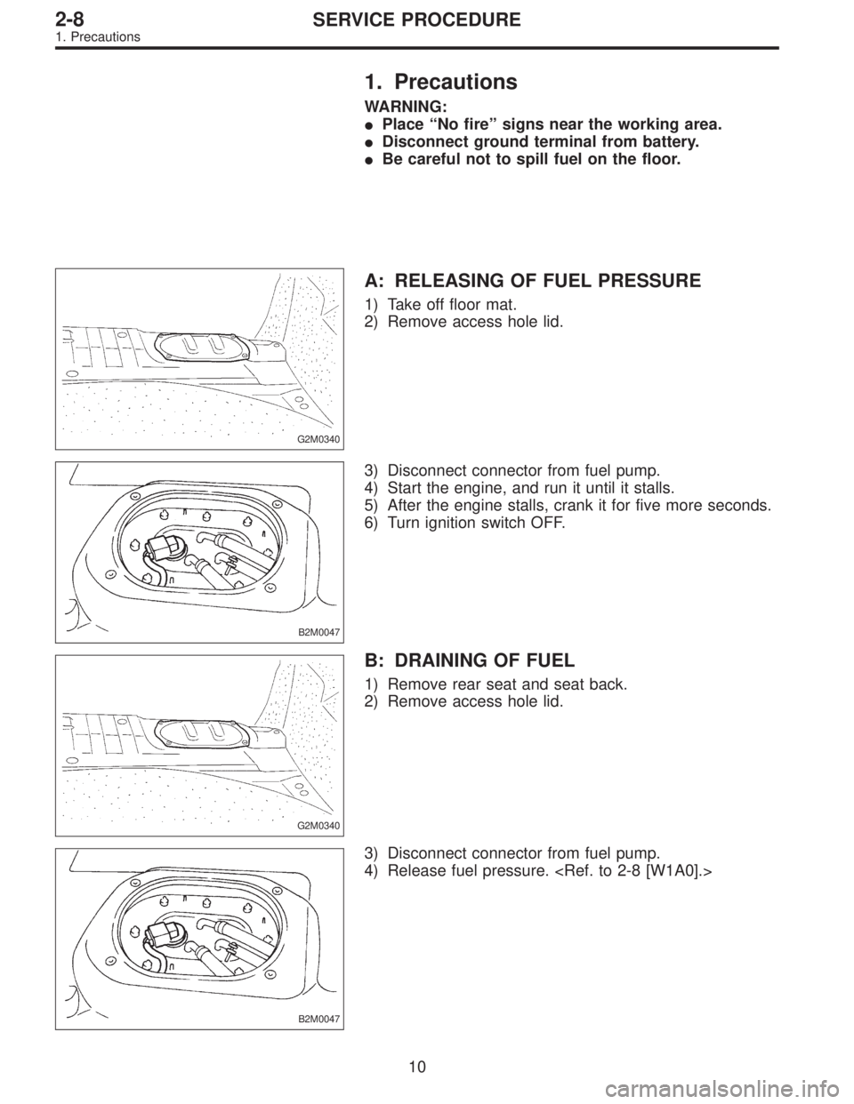
1. Precautions
WARNING:
�Place “No fire” signs near the working area.
�Disconnect ground terminal from battery.
�Be careful not to spill fuel on the floor.
G2M0340
A: RELEASING OF FUEL PRESSURE
1) Take off floor mat.
2) Remove access hole lid.
B2M0047
3) Disconnect connector from fuel pump.
4) Start the engine, and run it until it stalls.
5) After the engine stalls, crank it for five more seconds.
6) Turn ignition switch OFF.
G2M0340
B: DRAINING OF FUEL
1) Remove rear seat and seat back.
2) Remove access hole lid.
B2M0047
3) Disconnect connector from fuel pump.
4) Release fuel pressure.
10
2-8SERVICE PROCEDURE
1. Precautions
Page 531 of 3342
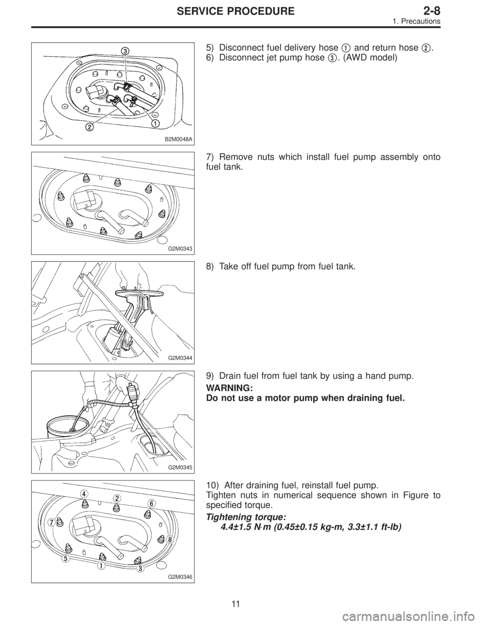
B2M0048A
5) Disconnect fuel delivery hose�1and return hose�2.
6) Disconnect jet pump hose�
3. (AWD model)
G2M0343
7) Remove nuts which install fuel pump assembly onto
fuel tank.
G2M0344
8) Take off fuel pump from fuel tank.
G2M0345
9) Drain fuel from fuel tank by using a hand pump.
WARNING:
Do not use a motor pump when draining fuel.
G2M0346
10) After draining fuel, reinstall fuel pump.
Tighten nuts in numerical sequence shown in Figure to
specified torque.
Tightening torque:
4.4±1.5 N⋅m (0.45±0.15 kg-m, 3.3±1.1 ft-lb)
11
2-8SERVICE PROCEDURE
1. Precautions