Page 921 of 3342

�1Plug
�
2Snap ring
�
3Oil seal
�
4Manual shaft
�
5Range select lever (Plastic body type)
�
6Inhibitor switch ASSY (Plastic body type)
�
7Nipple
�
8Plate ASSY
�
9Air breather hose
�
10Oil level gauge
�
11O-ring
�
12Oil charger pipe
�
13Gasket
�
14Relief valve
�
15Pipe
�
16Gasket
�
17Transmission cover (FWD model)
�
18Shim
�
19Roller bearing
�
20Parking support
�
21Ball bearing
�
22Parking rod
�
23Return spring
�
24Shaft
�
25Parking pawl
�
26Gasket
�
27Inlet pipe
�
28Test plug
�
29O-ring
�
30Spring
�
31O-ring
�
32Accumulator piston (N-D)
�
33O-ring
�
34O-ring
�
35Accumulator piston (2-3)
�
36O-ring
�
37Spring
�
38O-ring
�
39Accumulator piston (1-2)
�
40O-ring�
41Spring
�
42O-ring
�
43Accumulator piston (3-4)
�
44O-ring
�
45Spring
�
46Magnet
�
47Oil pan
�
48Gasket
�
49Drain plug
�
50Detention spring
�
51Pipe (AWD model)
�
52Plug (FWD model)
�
53Gasket (FWD model)
�
54Gasket
�
55Outlet pipe
�
56Spring
�
57Ball
�
58Stopper
�
59Manual lever
�
60Manual plate
�
61Spring pin
�
62Stud bolt
�
63Range select lever (Aluminum body type)
�
64Inhibitor switch (Aluminum body type)
�
65Clip (Aluminum body type)
Tightening torque: N⋅m (kg-m, ft-lb)
T1: 3.4±0.5 (0.35±0.05, 2.5±0.4)
T2: 4.9±0.5 (0.50±0.05, 3.6±0.4)
T3: 5.9±1.0 (0.60±0.10, 4.3±0.7)
T4: 6.4±0.5 (0.65±0.05, 4.7±0.4)
T5: 7.8±1.0 (0.80±0.10, 5.8±0.7)
T6: 12.7±1.0 (1.30±0.10, 9.4±0.7)
T7: 17.7±2.9 (1.80±0.30, 13.0±2.2)
T8: 24.5±2.0 (2.50±0.20, 18.1±1.4)
T9: 30.9±3.4 (3.15±0.35, 22.8±2.5)
T10: 34.3±2.9 (3.50±0.30, 25.3±2.2)
T11: 47.1±2.0 (4.80±0.20, 34.7±1.4)
T12: 47.1±4.9 (4.80±0.50, 34.7±3.6)
15
3-2COMPONENT PARTS
5. Transmission Case, Transmission Cover and Control Device
Page 937 of 3342
G3M0297
C: REMOVAL AND INSTALLATION
1. SHIFT SOLENOID, DUTY SOLENOID AND VALVE
BODY
1) Removal
(1) Clean transmission exterior.
(2) Drain ATF completely.
NOTE:
Tighten ATF drain plug after draining ATF.
Tightening torque:
25±2 N⋅m (2.5±0.2 kg-m, 18.1±1.4 ft-lb)
G3M0861
(3) Remove oil pan and gasket.
NOTE:
Drain oil into a container.
(4) Disconnect solenoid valve connectors.
Remove connectors from clips and disconnect connec-
tors at 4 places.
G3M0862
(5) Remove oil strainer.
Disconnect oil pipe by removing the two bolts, and
remove four bolts and oil strainer.
NOTE:
Be careful because oil flows from oil strainer.
31
3-2SERVICE PROCEDURE
2. On-Car Service
Page 940 of 3342
G3M0304
2. DUTY SOLENOID C AND TRANSFER VALVE BODY
1) Removal
(1) Remove pitching stopper.
G3M0297
(2) Raise vehicle and drain ATF.
G3M0305
(3) Remove front exhaust pipe.
Disconnect oxygen sensor connector, and remove
exhaust pipe.
G3M0782
(4) Remove propeller shaft.
NOTE:
Before removing propeller shaft, scribe matching marks on
propeller shaft and rear differential coupling.
G3M0306
(5) Remove rear crossmember.
�Support transmission using a transmission jack and
raise slightly.
�Remove bolts and nuts as shown in Figure.
34
3-2SERVICE PROCEDURE
2. On-Car Service
Page 1046 of 3342
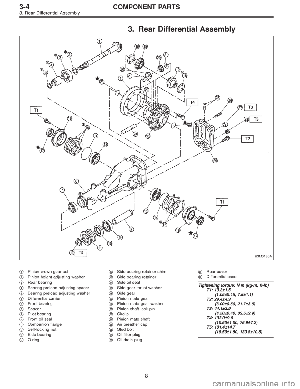
3. Rear Differential Assembly
B3M0130A
�1Pinion crown gear set
�
2Pinion height adjusting washer
�
3Rear bearing
�
4Bearing preload adjusting spacer
�
5Bearing preload adjusting washer
�
6Differential carrier
�
7Front bearing
�
8Spacer
�
9Pilot bearing
�
10Front oil seal
�
11Companion flange
�
12Self-locking nut
�
13Side bearing
�
14O-ring�
15Side bearing retainer shim
�
16Side bearing retainer
�
17Side oil seal
�
18Side gear thrust washer
�
19Side gear
�
20Pinion mate gear
�
21Pinion mate gear washer
�
22Pinion shaft lock pin
�
23Circlip
�
24Pinion mate shaft
�
25Air breather cap
�
26Stud bolt
�
27Oil filler plug
�
28Oil drain plug�
29Rear cover
�
30Differential case
Tightening torque: N⋅m (kg-m, ft-lb)
T1: 10.3±1.5
(1.05±0.15, 7.6±1.1)
T2: 29.4±4.9
(3.00±0.50, 21.7±3.6)
T3: 44.1±3.9
(4.50±0.40, 32.5±2.9)
T4: 103.0±9.8
(10.50±1.00, 75.9±7.2)
T5: 181.4±14.7
(18.50±1.50, 133.8±10.8)
8
3-4COMPONENT PARTS
3. Rear Differential Assembly
Page 1060 of 3342
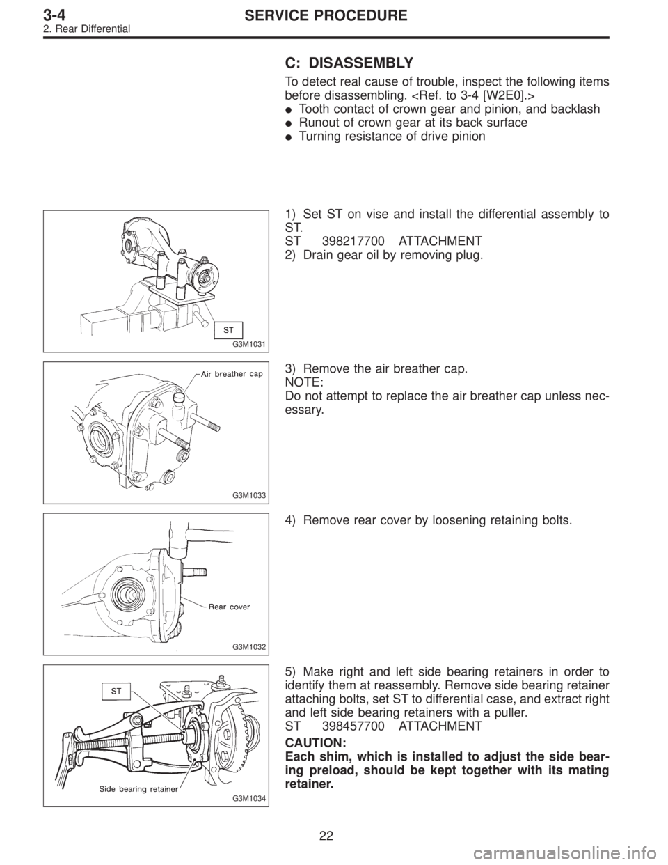
C: DISASSEMBLY
To detect real cause of trouble, inspect the following items
before disassembling.
�Tooth contact of crown gear and pinion, and backlash
�Runout of crown gear at its back surface
�Turning resistance of drive pinion
G3M1031
1) Set ST on vise and install the differential assembly to
ST.
ST 398217700 ATTACHMENT
2) Drain gear oil by removing plug.
G3M1033
3) Remove the air breather cap.
NOTE:
Do not attempt to replace the air breather cap unless nec-
essary.
G3M1032
4) Remove rear cover by loosening retaining bolts.
G3M1034
5) Make right and left side bearing retainers in order to
identify them at reassembly. Remove side bearing retainer
attaching bolts, set ST to differential case, and extract right
and left side bearing retainers with a puller.
ST 398457700 ATTACHMENT
CAUTION:
Each shim, which is installed to adjust the side bear-
ing preload, should be kept together with its mating
retainer.
22
3-4SERVICE PROCEDURE
2. Rear Differential
Page 1078 of 3342
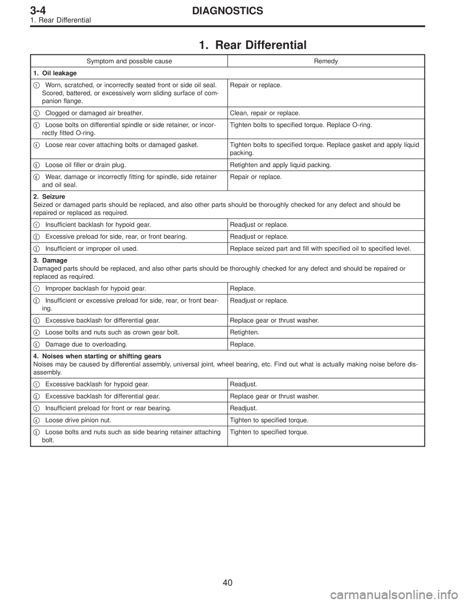
1. Rear Differential
Symptom and possible cause Remedy
1. Oil leakage
�
1Worn, scratched, or incorrectly seated front or side oil seal.
Scored, battered, or excessively worn sliding surface of com-
panion flange.Repair or replace.
�
2Clogged or damaged air breather. Clean, repair or replace.
�
3Loose bolts on differential spindle or side retainer, or incor-
rectly fitted O-ring.Tighten bolts to specified torque. Replace O-ring.
�
4Loose rear cover attaching bolts or damaged gasket. Tighten bolts to specified torque. Replace gasket and apply liquid
packing.
�
5Loose oil filler or drain plug. Retighten and apply liquid packing.
�
6Wear, damage or incorrectly fitting for spindle, side retainer
and oil seal.Repair or replace.
2. Seizure
Seized or damaged parts should be replaced, and also other parts should be thoroughly checked for any defect and should be
repaired or replaced as required.
�
1Insufficient backlash for hypoid gear. Readjust or replace.
�
2Excessive preload for side, rear, or front bearing. Readjust or replace.
�
3Insufficient or improper oil used. Replace seized part and fill with specified oil to specified level.
3. Damage
Damaged parts should be replaced, and also other parts should be thoroughly checked for any defect and should be repaired or
replaced as required.
�
1Improper backlash for hypoid gear. Replace.
�
2Insufficient or excessive preload for side, rear, or front bear-
ing.Readjust or replace.
�
3Excessive backlash for differential gear. Replace gear or thrust washer.
�
4Loose bolts and nuts such as crown gear bolt. Retighten.
�
5Damage due to overloading. Replace.
4. Noises when starting or shifting gears
Noises may be caused by differential assembly, universal joint, wheel bearing, etc. Find out what is actually making noise before dis-
assembly.
�
1Excessive backlash for hypoid gear. Readjust.
�
2Excessive backlash for differential gear. Replace gear or thrust washer.
�
3Insufficient preload for front or rear bearing. Readjust.
�
4Loose drive pinion nut. Tighten to specified torque.
�
5Loose bolts and nuts such as side bearing retainer attaching
bolt.Tighten to specified torque.
40
3-4DIAGNOSTICS
1. Rear Differential
Page 1214 of 3342
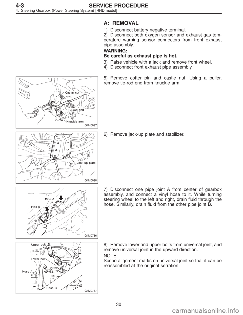
A: REMOVAL
1) Disconnect battery negative terminal.
2) Disconnect both oxygen sensor and exhaust gas tem-
perature warning sensor connectors from front exhaust
pipe assembly.
WARNING:
Be careful as exhaust pipe is hot.
3) Raise vehicle with a jack and remove front wheel.
4) Disconnect front exhaust pipe assembly.
G4M0097
5) Remove cotter pin and castle nut. Using a puller,
remove tie-rod end from knuckle arm.
G4M0098
6) Remove jack-up plate and stabilizer.
G4M0786
7) Disconnect one pipe joint A from center of gearbox
assembly, and connect a vinyl hose to it. While turning
steering wheel to the left and right, drain fluid through the
hose. Similarly, drain fluid from the other pipe joint B.
G4M0787
8) Remove lower and upper bolts from universal joint, and
remove universal joint in the upward direction.
NOTE:
Scribe alignment marks on universal joint so that it can be
reassembled at the original serration.
30
4-3SERVICE PROCEDURE
4. Steering Gearbox (Power Steering System) [RHD model]
Page 1254 of 3342
B4M1160
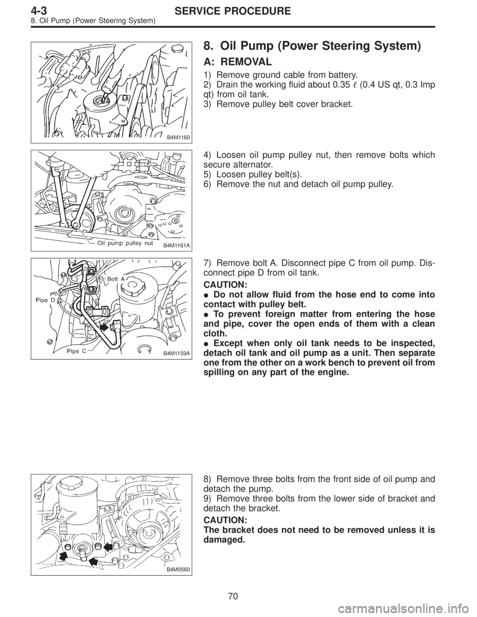
8. Oil Pump (Power Steering System)
A: REMOVAL
1) Remove ground cable from battery.
2) Drain the working fluid about 0.35�(0.4 US qt, 0.3 Imp
qt) from oil tank.
3) Remove pulley belt cover bracket.
B4M1161A
4) Loosen oil pump pulley nut, then remove bolts which
secure alternator.
5) Loosen pulley belt(s).
6) Remove the nut and detach oil pump pulley.
B4M1159A
7) Remove bolt A. Disconnect pipe C from oil pump. Dis-
connect pipe D from oil tank.
CAUTION:
�Do not allow fluid from the hose end to come into
contact with pulley belt.
�To prevent foreign matter from entering the hose
and pipe, cover the open ends of them with a clean
cloth.
�Except when only oil tank needs to be inspected,
detach oil tank and oil pump as a unit. Then separate
one from the other on a work bench to prevent oil from
spilling on any part of the engine.
B4M0560
8) Remove three bolts from the front side of oil pump and
detach the pump.
9) Remove three bolts from the lower side of bracket and
detach the bracket.
CAUTION:
The bracket does not need to be removed unless it is
damaged.
70
4-3SERVICE PROCEDURE
8. Oil Pump (Power Steering System)