Page 615 of 3342
3. Transmission
A: REMOVAL
1. Open front hood fully, and support it with stay.
2. Disconnect battery ground terminal.
3. Remove air intake duct and chamber.
4. Disconnect connectors and cables.
5. Remove starter.
6. Remove pitching stopper.
AT model
7. Separate torque converter from drive plate.
8. Remove ATF level gauge.
9. Remove transmission connector bracket.
Hydraulic clutch model
10. Remove operating cylinder.
11. Set special tools.
12. Remove bolt which holds right upper side of transmission to
engine.
Hydraulic clutch model
13. Remove clutch damper.
14. Remove exhaust system.
�Front exhaust pipe
�Center exhaust pipe
�Rear exhaust pipe [AWD]
AT model
15. Drain ATF to remove ATF drain plug.
16. Disconnect ATF cooler hose from pipe on transmission side,
and remove ATF level gauge guide.
AWD model
17. Remove propeller shaft.
�A
�
�
�
�
�
�
�
�
�
�
�
�
�
�
27
2-11SERVICE PROCEDURE
3. Transmission
Page 640 of 3342
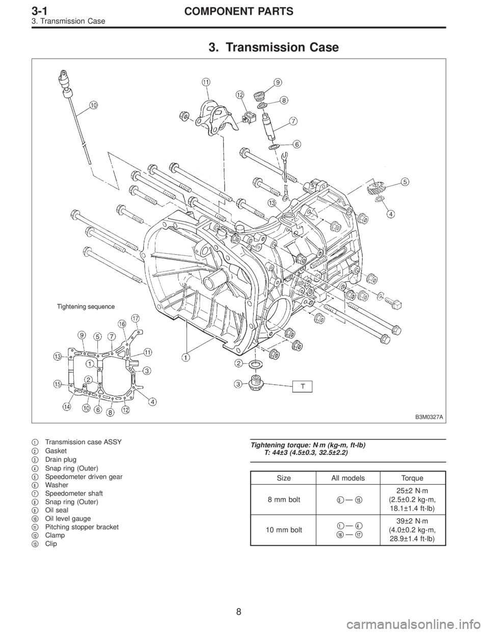
3. Transmission Case
B3M0327A
�1Transmission case ASSY
�
2Gasket
�
3Drain plug
�
4Snap ring (Outer)
�
5Speedometer driven gear
�
6Washer
�
7Speedometer shaft
�
8Snap ring (Outer)
�
9Oil seal
�
10Oil level gauge
�
11Pitching stopper bracket
�
12Clamp
�
13Clip
Tightening torque: N⋅m (kg-m, ft-lb)
T: 44±3 (4.5±0.3, 32.5±2.2)
Size All models Torque
8 mm bolt�
5—�15
25±2 N⋅m
(2.5±0.2 kg-m,
18.1±1.4 ft-lb)
10 mm bolt�
1—�4
�16—�17
39±2 N⋅m
(4.0±0.2 kg-m,
28.9±1.4 ft-lb)
8
3-1COMPONENT PARTS
3. Transmission Case
Page 721 of 3342

�
6Inhibitor switch ASSY (Plastic body type)
�
7Nipple
�
8Plate ASSY
�
9Air breather hose
�
10Oil level gauge")
�1Plug
�
2Snap ring
�
3Oil seal
�
4Manual shaft
�
5Range select lever (Plastic body type)
�
6Inhibitor switch ASSY (Plastic body type)
�
7Nipple
�
8Plate ASSY
�
9Air breather hose
�
10Oil level gauge
�
11O-ring
�
12Oil charger pipe
�
13Gasket
�
14Relief valve
�
15Pipe
�
16Gasket
�
17Transmission cover (FWD model)
�
18Shim
�
19Roller bearing
�
20Parking support
�
21Ball bearing
�
22Parking rod
�
23Return spring
�
24Shaft
�
25Parking pawl
�
26Gasket
�
27Inlet pipe
�
28Test plug
�
29O-ring
�
30Spring
�
31O-ring
�
32Accumulator piston (N-D)
�
33O-ring
�
34O-ring
�
35Accumulator piston (2-3)
�
36O-ring
�
37Spring
�
38O-ring
�
39Accumulator piston (1-2)
�
40O-ring�
41Spring
�
42O-ring
�
43Accumulator piston (3-4)
�
44O-ring
�
45Spring
�
46Magnet
�
47Oil pan
�
48Gasket
�
49Drain plug
�
50Detention spring
�
51Pipe (AWD model)
�
52Plug (FWD model)
�
53Gasket (FWD model)
�
54Gasket
�
55Outlet pipe
�
56Spring
�
57Ball
�
58Stopper
�
59Manual lever
�
60Manual plate
�
61Spring pin
�
62Stud bolt
�
63Range select lever (Aluminum body type)
�
64Inhibitor switch (Aluminum body type)
�
65Clip (Aluminum body type)
Tightening torque: N⋅m (kg-m, ft-lb)
T1: 3.4±0.5 (0.35±0.05, 2.5±0.4)
T2: 4.9±0.5 (0.50±0.05, 3.6±0.4)
T3: 5.9±1.0 (0.60±0.10, 4.3±0.7)
T4: 6.4±0.5 (0.65±0.05, 4.7±0.4)
T5: 7.8±1.0 (0.80±0.10, 5.8±0.7)
T6: 12.7±1.0 (1.30±0.10, 9.4±0.7)
T7: 17.7±2.9 (1.80±0.30, 13.0±2.2)
T8: 24.5±2.0 (2.50±0.20, 18.1±1.4)
T9: 30.9±3.4 (3.15±0.35, 22.8±2.5)
T10: 34.3±2.9 (3.50±0.30, 25.3±2.2)
T11: 47.1±2.0 (4.80±0.20, 34.7±1.4)
T12: 47.1±4.9 (4.80±0.50, 34.7±3.6)
15
3-2COMPONENT PARTS
5. Transmission Case, Transmission Cover and Control Device
Page 737 of 3342
G3M0297
C: REMOVAL AND INSTALLATION
1. SHIFT SOLENOID, DUTY SOLENOID AND VALVE
BODY
1) Removal
(1) Clean transmission exterior.
(2) Drain ATF completely.
NOTE:
Tighten ATF drain plug after draining ATF.
Tightening torque:
25±2 N⋅m (2.5±0.2 kg-m, 18.1±1.4 ft-lb)
G3M0861
(3) Remove oil pan and gasket.
NOTE:
Drain oil into a container.
(4) Disconnect solenoid valve connectors.
Remove connectors from clips and disconnect connec-
tors at 4 places.
G3M0862
(5) Remove oil strainer.
Disconnect oil pipe by removing the two bolts, and
remove four bolts and oil strainer.
NOTE:
Be careful because oil flows from oil strainer.
31
3-2SERVICE PROCEDURE
2. On-Car Service
Page 740 of 3342
G3M0304
2. DUTY SOLENOID C AND TRANSFER VALVE BODY
1) Removal
(1) Remove pitching stopper.
G3M0297
(2) Raise vehicle and drain ATF.
G3M0305
(3) Remove front exhaust pipe.
Disconnect oxygen sensor connector, and remove
exhaust pipe.
G3M0782
(4) Remove propeller shaft.
NOTE:
Before removing propeller shaft, scribe matching marks on
propeller shaft and rear differential coupling.
G3M0306
(5) Remove rear crossmember.
�Support transmission using a transmission jack and
raise slightly.
�Remove bolts and nuts as shown in Figure.
34
3-2SERVICE PROCEDURE
2. On-Car Service
Page 821 of 3342

�
6Inhibitor switch ASSY (Plastic body type)
�
7Nipple
�
8Plate ASSY
�
9Air breather hose
�
10Oil level gauge")
�1Plug
�
2Snap ring
�
3Oil seal
�
4Manual shaft
�
5Range select lever (Plastic body type)
�
6Inhibitor switch ASSY (Plastic body type)
�
7Nipple
�
8Plate ASSY
�
9Air breather hose
�
10Oil level gauge
�
11O-ring
�
12Oil charger pipe
�
13Gasket
�
14Relief valve
�
15Pipe
�
16Gasket
�
17Transmission cover (FWD model)
�
18Shim
�
19Roller bearing
�
20Parking support
�
21Ball bearing
�
22Parking rod
�
23Return spring
�
24Shaft
�
25Parking pawl
�
26Gasket
�
27Inlet pipe
�
28Test plug
�
29O-ring
�
30Spring
�
31O-ring
�
32Accumulator piston (N-D)
�
33O-ring
�
34O-ring
�
35Accumulator piston (2-3)
�
36O-ring
�
37Spring
�
38O-ring
�
39Accumulator piston (1-2)
�
40O-ring�
41Spring
�
42O-ring
�
43Accumulator piston (3-4)
�
44O-ring
�
45Spring
�
46Magnet
�
47Oil pan
�
48Gasket
�
49Drain plug
�
50Detention spring
�
51Pipe (AWD model)
�
52Plug (FWD model)
�
53Gasket (FWD model)
�
54Gasket
�
55Outlet pipe
�
56Spring
�
57Ball
�
58Stopper
�
59Manual lever
�
60Manual plate
�
61Spring pin
�
62Stud bolt
�
63Range select lever (Aluminum body type)
�
64Inhibitor switch (Aluminum body type)
�
65Clip (Aluminum body type)
Tightening torque: N⋅m (kg-m, ft-lb)
T1: 3.4±0.5 (0.35±0.05, 2.5±0.4)
T2: 4.9±0.5 (0.50±0.05, 3.6±0.4)
T3: 5.9±1.0 (0.60±0.10, 4.3±0.7)
T4: 6.4±0.5 (0.65±0.05, 4.7±0.4)
T5: 7.8±1.0 (0.80±0.10, 5.8±0.7)
T6: 12.7±1.0 (1.30±0.10, 9.4±0.7)
T7: 17.7±2.9 (1.80±0.30, 13.0±2.2)
T8: 24.5±2.0 (2.50±0.20, 18.1±1.4)
T9: 30.9±3.4 (3.15±0.35, 22.8±2.5)
T10: 34.3±2.9 (3.50±0.30, 25.3±2.2)
T11: 47.1±2.0 (4.80±0.20, 34.7±1.4)
T12: 47.1±4.9 (4.80±0.50, 34.7±3.6)
15
3-2COMPONENT PARTS
5. Transmission Case, Transmission Cover and Control Device
Page 837 of 3342
G3M0297
C: REMOVAL AND INSTALLATION
1. SHIFT SOLENOID, DUTY SOLENOID AND VALVE
BODY
1) Removal
(1) Clean transmission exterior.
(2) Drain ATF completely.
NOTE:
Tighten ATF drain plug after draining ATF.
Tightening torque:
25±2 N⋅m (2.5±0.2 kg-m, 18.1±1.4 ft-lb)
G3M0861
(3) Remove oil pan and gasket.
NOTE:
Drain oil into a container.
(4) Disconnect solenoid valve connectors.
Remove connectors from clips and disconnect connec-
tors at 4 places.
G3M0862
(5) Remove oil strainer.
Disconnect oil pipe by removing the two bolts, and
remove four bolts and oil strainer.
NOTE:
Be careful because oil flows from oil strainer.
31
3-2SERVICE PROCEDURE
2. On-Car Service
Page 840 of 3342
G3M0304
2. DUTY SOLENOID C AND TRANSFER VALVE BODY
1) Removal
(1) Remove pitching stopper.
G3M0297
(2) Raise vehicle and drain ATF.
G3M0305
(3) Remove front exhaust pipe.
Disconnect oxygen sensor connector, and remove
exhaust pipe.
G3M0782
(4) Remove propeller shaft.
NOTE:
Before removing propeller shaft, scribe matching marks on
propeller shaft and rear differential coupling.
G3M0306
(5) Remove rear crossmember.
�Support transmission using a transmission jack and
raise slightly.
�Remove bolts and nuts as shown in Figure.
34
3-2SERVICE PROCEDURE
2. On-Car Service

 Removal
(1) Clean transmission exterior.
(2) Drain ATF completely.
NOTE:
Tighten ATF drain plug after draining AT")
 Removal
(1) Remove pitching stopper.
G3M0297
(2) Raise vehicle and drain ATF.
G3M0305
(3) Remove front exhaust pipe.
Disconnect oxygen sensor conn")
 Removal
(1) Clean transmission exterior.
(2) Drain ATF completely.
NOTE:
Tighten ATF drain plug after draining AT")
 Removal
(1) Remove pitching stopper.
G3M0297
(2) Raise vehicle and drain ATF.
G3M0305
(3) Remove front exhaust pipe.
Disconnect oxygen sensor conn")