Page 1268 of 3342
B4M1193A
1) Install STs to power steering pump.
(1) Drain the power steering fluid about 0.35�(0.4 US
qt, 0.3 Imp qt) from oil tank.
(2) Remove two bolts securing power steering pipes to
engine.
(3) Install ST1, 2 and 3 between power steering pump
and pipes using gasket (Part No. 34621AC020) and
bolt (Part No. 34620AC010).
ST1 925711000 PRESSURE GAUGE
ST2 34099AC020 ADAPTER B
ST3 34099AC010 ADAPTER A
(4) Replenish power steering fluid up to specified level.
2) Using STs, measure regulator pressure.
Regulator pressure:
981 kPa (10 kg/cm
2, 142 psi) or less
B4M1162A
3) Using STs, measure relief pressure.
Relief pressure:
7,159—7,748 kPa
(73—79 kg/cm
2, 1,038—1,123 psi)
84
4-3DIAGNOSTICS
1. Power Steering
Page 1491 of 3342
![SUBARU LEGACY 1997 Service Repair Manual G4M0640
13. Receiver Drier
A: REMOVAL AND INSTALLATION
1) Disconnect battery negative terminal.
2) Discharge refrigerant using refrigerant recovery system.
<Ref. to 4-7 [W601].>
3) Disconnect pressure](/manual-img/17/57434/w960_57434-1490.png "SUBARU LEGACY 1997 Service Repair Manual G4M0640
13. Receiver Drier
A: REMOVAL AND INSTALLATION
1) Disconnect battery negative terminal.
2) Discharge refrigerant using refrigerant recovery system.
<Ref. to 4-7 [W601].>
3) Disconnect pressure")
G4M0640
13. Receiver Drier
A: REMOVAL AND INSTALLATION
1) Disconnect battery negative terminal.
2) Discharge refrigerant using refrigerant recovery system.
3) Disconnect pressure switch harness�
1.
4) Disconnect pipes�
2.
5) Remove mounting bolt�
3and remove receiver drier.
CAUTION:
The receiver drier contains a desiccant. Be sure to put
a blind plug in the detached receiver drier to protect it
from moisture.
6) Install the receiver drier in the reverse order of removal.
7) Charge refrigerant.
G4M0641
14. Evaporator Unit
A: REMOVAL AND INSTALLATION
1) Disconnect battery negative terminal.
2) Discharge refrigerant using refrigerant recovery system.
3) Disconnect discharge pipe, suction pipe and grommets.
B5M0025
4) Remove glove box and pocket back panel.
[W1A0].>
G4M0642
5) Disconnect the harness connector from evaporator.
6) Disconnect drain hose.
7) Remove evaporator mounting bolt and nut.
8) Install the evaporator in the reverse order of removal.
9) Charge refrigerant.
36
4-7SERVICE PROCEDURE
13. Receiver Drier - 14. Evaporator Unit
Page 1492 of 3342
![SUBARU LEGACY 1997 Service Repair Manual G4M0640
13. Receiver Drier
A: REMOVAL AND INSTALLATION
1) Disconnect battery negative terminal.
2) Discharge refrigerant using refrigerant recovery system.
<Ref. to 4-7 [W601].>
3) Disconnect pressure](/manual-img/17/57434/w960_57434-1491.png "SUBARU LEGACY 1997 Service Repair Manual G4M0640
13. Receiver Drier
A: REMOVAL AND INSTALLATION
1) Disconnect battery negative terminal.
2) Discharge refrigerant using refrigerant recovery system.
<Ref. to 4-7 [W601].>
3) Disconnect pressure")
G4M0640
13. Receiver Drier
A: REMOVAL AND INSTALLATION
1) Disconnect battery negative terminal.
2) Discharge refrigerant using refrigerant recovery system.
3) Disconnect pressure switch harness�
1.
4) Disconnect pipes�
2.
5) Remove mounting bolt�
3and remove receiver drier.
CAUTION:
The receiver drier contains a desiccant. Be sure to put
a blind plug in the detached receiver drier to protect it
from moisture.
6) Install the receiver drier in the reverse order of removal.
7) Charge refrigerant.
G4M0641
14. Evaporator Unit
A: REMOVAL AND INSTALLATION
1) Disconnect battery negative terminal.
2) Discharge refrigerant using refrigerant recovery system.
3) Disconnect discharge pipe, suction pipe and grommets.
B5M0025
4) Remove glove box and pocket back panel.
[W1A0].>
G4M0642
5) Disconnect the harness connector from evaporator.
6) Disconnect drain hose.
7) Remove evaporator mounting bolt and nut.
8) Install the evaporator in the reverse order of removal.
9) Charge refrigerant.
36
4-7SERVICE PROCEDURE
13. Receiver Drier - 14. Evaporator Unit
Page 1572 of 3342
B5M0310A
3. SUNROOF FRAME
1) Remove sunroof switch, center and rear room lamps.
2) Remove roof trim, rear quarter trim, pillar trim, etc.
3) Remove glass lid assembly.
4) Remove two harness support clips.
G5M0205
5) Disconnect harness clips and connector of sunroof
motor.
6) Disconnect front and rear drain tubes.
CAUTION:
When installing drain tube, insert it securely into drain
pipe.
Length A:
15 mm (0.59 in) or more
B5M0312
7) Remove eight nuts.
B5M0382A
8) Remove set bracket mounting bolts.
9) Remove sunroof frame.
B: INSTALLATION
Installation is in the reverse order of removal.
57
5-1SERVICE PROCEDURE
16. Sunroof
Page 1748 of 3342
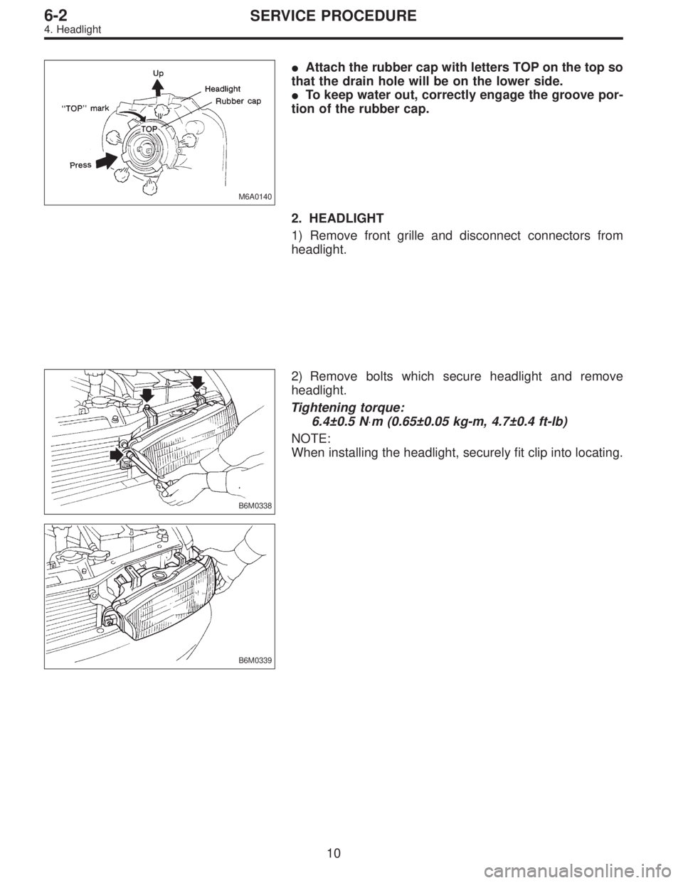
M6A0140
�Attach the rubber cap with letters TOP on the top so
that the drain hole will be on the lower side.
�To keep water out, correctly engage the groove por-
tion of the rubber cap.
2. HEADLIGHT
1) Remove front grille and disconnect connectors from
headlight.
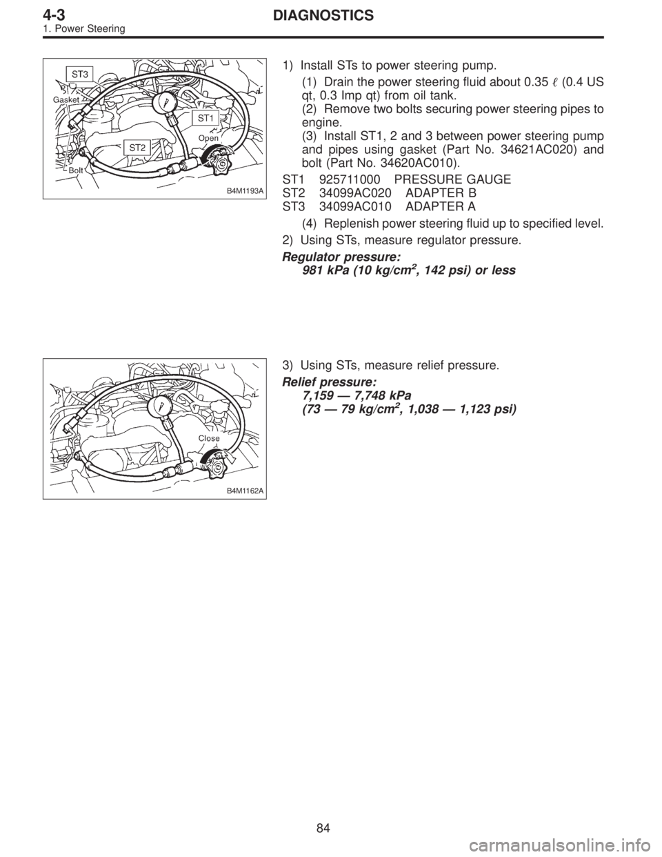
B6M0338
2) Remove bolts which secure headlight and remove
headlight.
Tightening torque:
6.4±0.5 N⋅m (0.65±0.05 kg-m, 4.7±0.4 ft-lb)
NOTE:
When installing the headlight, securely fit clip into locating.
B6M0339
10
6-2SERVICE PROCEDURE
4. Headlight
Page 1792 of 3342
 Disconnect connector from speaker.
4) Remove screws which secure the speaker.
5) Remove door mount speaker.
3. REAR SPEAKER (SEDAN)
1) Remove rear seat cushion and rear backrest.
2) Remove")
B6M0162
3) Disconnect connector from speaker.
4) Remove screws which secure the speaker.
5) Remove door mount speaker.
3. REAR SPEAKER (SEDAN)
1) Remove rear seat cushion and rear backrest.
2) Remove left and right rear quarter trim panels.
3) Remove rear shelf trim panel.
4) Remove screws which secure speaker.
5) Remove speaker while disconnecting connector from
speaker.
4. REAR SPEAKER (WAGON)
1) Remove door trim panel.
2) Disconnect connector from speaker.
3) Remove screws which secure the speaker.
4) Remove speaker.
B6M0147A
5. POWER ANTENNA
1) Remove left side trunk trim (SEDAN), or left side rear
lower quarter trim (WAGON).
2) Remove special nut (SEDAN).
3) Remove bolt which secures power antenna.
4) Remove power antenna while disconnecting connector
and water drain hose.
B6M0149A
B: INSPECTION
1. POWER ANTENNA
1) Connect battery positive (+) terminal to terminal No. 3
and connect terminal No. 1 (SEDAN) or No. 6 (WAGON)
to ground. Ensure that antenna rod extends properly when
battery positive (+) terminal is connected to terminal No. 2
(SEDAN) or No. 4 (WAGON).
2) Ensure that antenna rod retracts properly when battery
positive (+) terminal is disconnected from terminal No. 2
(SEDAN) or No. 4 (WAGON).
47
6-2SERVICE PROCEDURE
20. Radio, Speaker and Antenna
![SUBARU LEGACY 1997 Service Repair Manual B5M0310A
3. SUNROOF FRAME
1) Remove sunroof switch, center and rear room lamps.
2) Remove roof trim, rear quarter trim, pillar trim, etc.
<Ref. to 5-3 [W5A0].>
3) Remove glass lid assembly.
4) Remove](/manual-img/17/57434/w960_57434-1571.png "SUBARU LEGACY 1997 Service Repair Manual B5M0310A
3. SUNROOF FRAME
1) Remove sunroof switch, center and rear room lamps.
2) Remove roof trim, rear quarter trim, pillar trim, etc.
<Ref. to 5-3 [W5A0].>
3) Remove glass lid assembly.
4) Remove")