Page 11 of 3342
BRAKES
[M13-5]
4-413
.
Anti-lock
Brake
System
(ABS)
[5
.3i
Type]
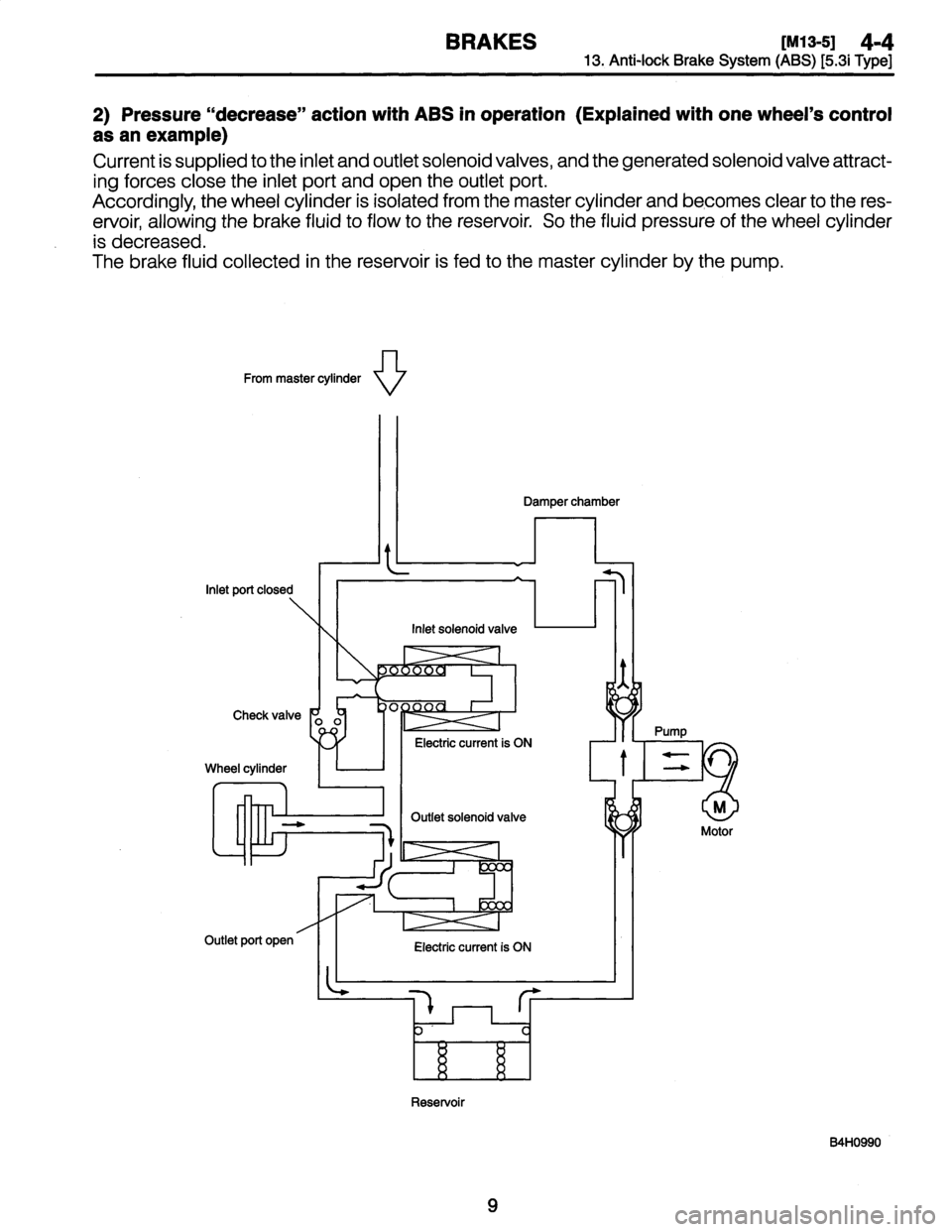
2)
Pressure
"decrease"
action
with
ABS
in
operation(Explained
with
one
wheel's
control
as
anexample)
Current
is
supplied
to
the
inlet
and
outlet
solenoid
valves,
and
the
generated
solenoid
valve
attract-
ing
forces
close
the
inlet
port
and
open
the
outlet
port
.
Accordingly,
the
wheel
cylinder
is
isolated
from
the
master
cylinder
and
becomes
clear
to
the
res-
ervoir,
allowing
the
brake
fluid
to
flow
to
the
reservoir
.
So
the
fluid
pressure
of
the
wheel
cylinder
is
decreased
.
The
brake
fluid
collected
in
the
reservoir
is
fed
to
the
master
cylinder
by
the
pump
.
From
master
cylinder
\/
\/
Reservoir
B4H0990
9
Page 12 of 3342
4-4
IM13-5]
BRAKES
13
.
Anti-lock
Brake
System
(ABS)
[5
.3i
Type]
3)
Pressure
"hold"
action
with
ABS
in
operation
(Explained
with
one
wheel's
control
asan
example)
Current
is
supplied
to
the
inlet
solenoid
valve,
and
the
generated
solenoid
valve
attracting
force
closes
the
inlet
port
.
Sinceno
current
is
supplied
to
the
outlet
solenoid
valve,
the
output
port
remains
in
a
closed
state
.
As
a
result,
the
wheel
cylinder,
master
cylinder
and
reservoir
are
blocked,
and
the
fluid
pressure
of
the
wheel
cylinder
is
maintained
constant
.
During
ABS
operation,the
pump
motor
continues
to
operate
.
From
master
cylinder
N~
O
Reservoir
B4H0991
10
Page 13 of 3342
BRAKES
[M13-5]
4-4
13
.
Anti-lock
Brake
System
(ABS)
[5
.3i
Type]
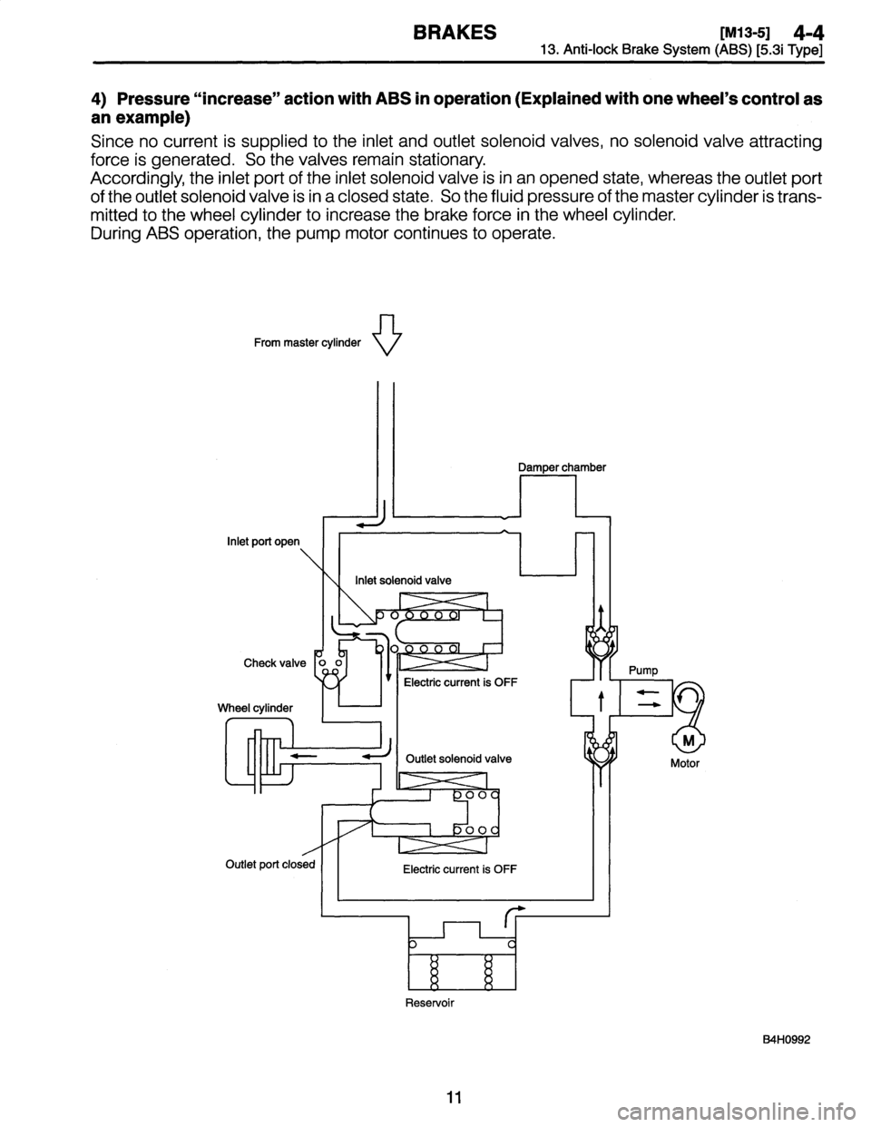
4)
Pressure
"increase"
action
with
ABS
in
operation(Explained
with
one
wheel's
control
as
anexample)
Since
no
current
is
supplied
to
the
inlet
and
outlet
solenoid
valves,
no
solenoidvalve
attracting
force
is
generated
.
So
the
valves
remain
stationary
.
Accordingly,
the
inlet
port
of
the
inlet
solenoid
valve
isin
an
opened
state,
whereas
the
outlet
port
of
the
outlet
solenoid
valve
is
in
a
closed
state
.
So
the
fluid
pressure
of
the
master
cylinder
is
trans-
mitted
to
the
wheel
cylinder
to
increase
the
brake
force
in
the
wheel
cylinder
.
During
ABS
operation,
the
pump
motor
continues
to
operate
.
From
master
cylinder
\
V
Reservoir
B4H0992
11
Page 14 of 3342
4-4
[M13-6l
BRAKES
13
.
Anti-lock
Brake
System
(
AB
S)
[5.3
i
Type]
6
.
ABS
CONTROL
CYCLE
CURVES
Refer
to
4-4
[M8-6]
-*1
7
.
ABS
WARNING
LIGHT
Refer
to
4-4
[M8-7]
-*1
S
.
G
SENSOR
Refer
to
4-4
[M12-8]
.*5
12
Page 22 of 3342
![SUBARU LEGACY 1997 Service Repair Manual
SERVICE
PROCEDURE
[w2sao1
4-4
25
.
ABS
Control
Module
and
Hydraulic
Control
Unit
(ABSCM&H/U)
[ABS
5
.3i
Type]
A
:
REMOVAL
1)
Disconnect
ground
cablefrom
battery
.
2)
Remove
air
intake
duct
fromen](/manual-img/17/57434/w960_57434-21.png "SUBARU LEGACY 1997 Service Repair Manual
SERVICE
PROCEDURE
[w2sao1
4-4
25
.
ABS
Control
Module
and
Hydraulic
Control
Unit
(ABSCM&H/U)
[ABS
5
.3i
Type]
A
:
REMOVAL
1)
Disconnect
ground
cablefrom
battery
.
2)
Remove
air
intake
duct
fromen")
SERVICE
PROCEDURE
[w2sao1
4-4
25
.
ABS
Control
Module
and
Hydraulic
Control
Unit
(ABSCM&H/U)
[ABS
5
.3i
Type]
A
:
REMOVAL
1)
Disconnect
ground
cablefrom
battery
.
2)
Remove
air
intake
duct
fromengine
compartment
to
facilitate
removal
of
ABSCM&H/U
.
3)
Use
an
air-gun
to
get
rid
of
water
around
the
ABSCM&H/U
.
CAUTION
:
The
contact
will
be
insufficient
if
the
terminal
gets
wet
.
4)
Pull
on
the
lock
of
the
ABSCM&H/U
connector
to
remove
it
.
5)
Disconnect
connector
from
ABSCM&H/U
.
CAUTION
:
Be
careful
not
tolet
water
or
other
foreign
matter
con-
tact
the
ABSCM&H/U
terminal
6)
Unlock
cable
clip
.
7)
Disconnect
brake
pipes
from
ABSCM&H/U
.
CAUTION
:
Wrap
brake
pipes
with
vinyl
bag
to
avoid
spilling
brake
fluid
on
vehicle
body
.
8)
Remove
ABSCM&H/U
fromengine
compartment
.
CAUTION
:
9
ABSCM&H/U
cannotbe
disassembled
.
Do
not
attempt
to
loosen
bolts
and
nuts
.
"
Do
not
drop
or
bump
ABSCM&H/U
.
"
Do
not
turn
the
ABSCM&H/U
upside
down
or
place
it
on
its
side
.
*
Be
careful
to
prevent
foreign
particles
from
getting
into
ABSCM&H/U
.
9
Apply
acoat
of
rust-preventive
wax
(Nippeco
LT
or
GB)
to
bracket
attaching
bolt
after
tightening
.
*
Do
not
pull
harness
disconnecting
harness
connector
.
7
Page 30 of 3342
SERVICE
PROCEDURE
Iwz7oo1
4-4
25
.
ABS
Control
Module
and
Hydraulic
Control
Unit
(ABSCM&H/U)
[ABS
5
.3i
Type]
-
27
.
G
Sensor
(ABS
5
.3i
Type)
E
:
INSTALLATION
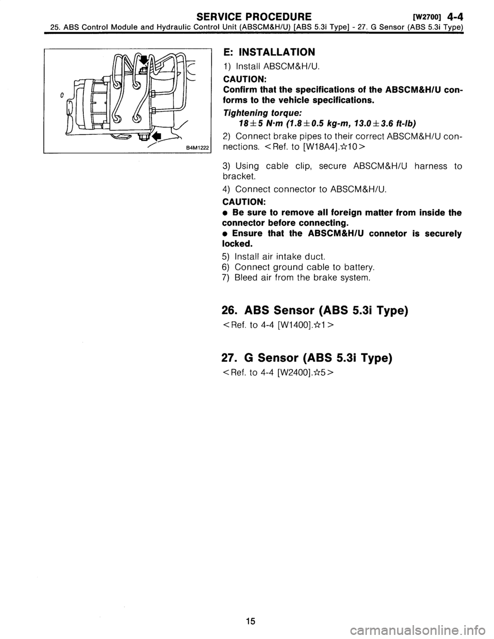
1)
Install
ABSCM&H/U
.
CAUTION
:
Confirm
that
the
specifications
of
the
ABSCM&H/U
con-
forms
to
the
vehicle
specifications
.
Tightening
torque
:
18
f
5
N~m
(1
.8
±
0
.5
kg-m,
13
.0
±
3
.6ft-Ib)
2)
Connect
brake
pipes
to
their
correct
ABSCM&H/U
con-
nections
.
<
Ref
.
to
[W18A4]
.*10
>
3)
Using
cable
clip,
secure
ABSCM&H/U
harness
to
bracket
.
4)
Connect
connector
to
ABSCM&H/U
.
CAUTION
:
9
Be
sure
to
remove
all
foreign
matter
from
inside
the
connector
before
connecting
.
9
Ensure
that
the
ABSCM&H/U
connetor
is
securely
locked
.
5)
Install
air
intake
duct
.
6)
Connect
ground
cable
to
battery
.
7)
Bleed
air
from
the
brake
system
.
26
.
ABS
Sensor
(ABS
5
.3i
Type)
<
Ref
.
to
4-4
[W1400]
.*1
>
27
.
G
Sensor
(ABS
5
.3i
Type)
Ref
.
to
4-4
[W2400]
.*5
>
15
Page 33 of 3342
BRAKES
[ABS
5
.3i
TYPE]
[TZBi]
4-4d
2
.
Pre-inspection
B
:
ELECTRICAL
INSPECTION
1
.
WARNING
LIGHT
ILLUMINATION
PATTERN
START
ON
r~
ON
OFF
Ignition
key
switch
Illuminates
.
Goes
out
.
Goes
out
.
ABS
warning
light1.5s
4
111
B4M0781A
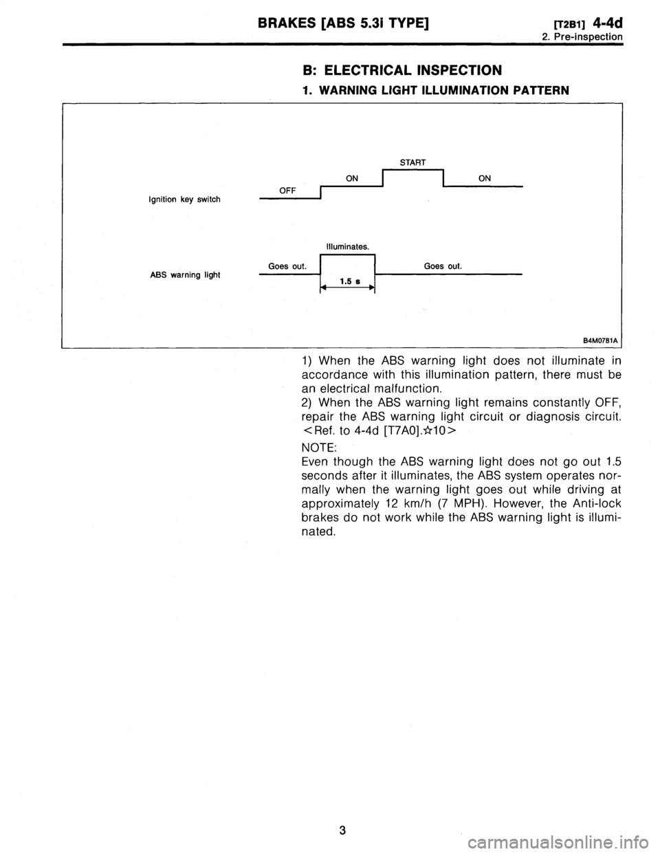
1)
When
the
ABS
warning
light
does
not
illuminate
in
accordance
with
this
illumination
pattern,
there
must
be
an
electrical
malfunction
.
2)
When
the
ABS
warning
light
remains
constantly
OFF,
repair
the
ABS
warning
light
circuit
or
diagnosis
circuit
.
.
to
4-4d
[T7A0]
.*10>
NOTE
:
Even
though
the
ABS
warning
light
does
not
go
out
1
.5
seconds
after
it
illuminates,
the
ABS
system
operates
nor-
mally
when
the
warning
light
goes
out
while
driving
at
approximately
12
km/h
(7
MPH)
.
However,
the
Anti-lock
brakes
do
not
work
while
the
ABS
warning
light
is
illumi-
nated
.
3
Page 41 of 3342

4-4d
[TSBO]
BRAKES
[ABS
5
.31
TYPE]
6
.
Diagnostics
Chart
for
On-board
Diagnosis
System
B
:
CHECK
LIST
FOR
INTERVIEW
Check
the
following
items
about
the
vehicle's
state
.
1
.
THE
STATE
OF
THE
ABS
WARNING
LIGHT
ABS
warning
light
O
Always
comes
on
.
D
Sometimes
O
Onlyonce
O
Does
not
come
on
o
When
/how
long
does
it
come
on?
:
Ignition
key
position
O
LOCK
D
ACC
OON
(before
starting
engine)
D
START
O
On
afterstarting
(Engine
is
running)
O
On
after
starting
(Engine
is
stop)
Timing
O
Immediately
afterignition
is
ON
.
O
Immediately
after
ignition
starts
.
O
When
advancing
km/h
to
km/h
MPH
to
MPH
D
While
traveling
at
a
constant
speed
km/h
MPH
D
When
decelerating
km/h
to
km/h
MPH
to
MPH
OWhen
turning
to
right
Steering
angle
:
deg
Steering
time
:
sec
D
When
turning
to
left
Steering
angle
:
deg
Steering
time
:
sec
D
When
moving
other
electrical
parts
Parts
name
Operating
condition
2
.
SYMPTOMS
ABS
operating
D
Performsno
work
.
condition
D
Operates
only
when
abruptly
applying
brakes
.
Vehicle
speed
:
km/h
MPH
~
How
to
step
on
brake
pedal
a)
Operating
time
:
sec
b)
Operating
noise
:
O
Produce
/
D
Does
not
produce
oWhat
kind
of
noise?
O
Knock
O
Gong
gong
D
Bong
a
Buzz
D
Gong
gong
buzz
O
Others
c)
Reaction
force
of
brake
pedal
O
Stick
O
Press
down
once
with
a
clunk
O
Press
and
released
D
Others
12
![SUBARU LEGACY 1997 Service Repair Manual
4-4
IM13-5]
BRAKES
13
.
Anti-lock
Brake
System
(ABS)
[5
.3i
Type]
3)
Pressure
"hold"
action
with
ABS
in
operation
(Explained
with
one
wheels
control
asan
example)
Current
is
supplied
to
the
inlet](/manual-img/17/57434/w960_57434-11.png "SUBARU LEGACY 1997 Service Repair Manual
4-4
IM13-5]
BRAKES
13
.
Anti-lock
Brake
System
(ABS)
[5
.3i
Type]
3)
Pressure
\"hold\"
action
with
ABS
in
operation
(Explained
with
one
wheels
control
asan
example)
Current
is
supplied
to
the
inlet")
![SUBARU LEGACY 1997 Service Repair Manual 4-4
[M13-6l
BRAKES
13
.
Anti-lock
Brake
System
(
AB
S)
[5.3
i
Type]
6
.
ABS
CONTROL
CYCLE
CURVES
Refer
to
4-4
[M8-6]
-*1
7
.
ABS
WARNING
LIGHT
Refer
to
4-4
[M8-7]
-*1
S
.
G
SENSOR
Refer
to
4-4
[](/manual-img/17/57434/w960_57434-13.png "SUBARU LEGACY 1997 Service Repair Manual 4-4
[M13-6l
BRAKES
13
.
Anti-lock
Brake
System
(
AB
S)
[5.3
i
Type]
6
.
ABS
CONTROL
CYCLE
CURVES
Refer
to
4-4
[M8-6]
-*1
7
.
ABS
WARNING
LIGHT
Refer
to
4-4
[M8-7]
-*1
S
.
G
SENSOR
Refer
to
4-4
[")