Page 253 of 3342
G2M0093
4) Connect oil pressure gauge hose to cylinder block.
5) Start the engine, and measure oil pressure.
Oil pressure:
98 kPa (1.0 kg/cm
2,14 psi) or more at 800 rpm
294 kPa (3.0 kg/cm2, 43 psi) or more at 5,000 rpm
CAUTION:
�If oil pressure is out of specification, check oil
pump, oil filter and lubrication line.
�If oil pressure warning light is turned ON and oil
pressure is in specification, replace oil pressure
switch.
NOTE:
The specified data is based on an engine oil temperature
of 80°C (176°F).
6) After measuring oil pressure, install oil pressure switch.
Tightening torque:
25±3 N⋅m (2.5±0.3 kg-m, 18.1±2.2 ft-lb)
7) Install generator and V-belt in the reverse order of
removal, and adjust the V-belt deflection.
8
2-2
6. Engine Oil Pressure
Page 255 of 3342
�When inspecting #2 and #4 cylinders;
(1) Disconnect battery cables, and then remove bat-
tery and battery carrier.
(2) Disconnect washer motor connectors.
(3) Disconnect rear window glass washer hose from
washer motor, then plug connection with a suitable cap.
(4) Remove the two bolts which holds washer tank,
then secure the tank away from working area.
(5) Disconnect spark plug cords from spark plugs (#2
and #4 cylinders).
(6) Remove under cover (LH).
(7) Place suitable container under the vehicle.
(8) Disconnect PCV hose from rocker cover (LH).
(9) Remove bolts, then remove rocker cover (LH).
B2M1228A
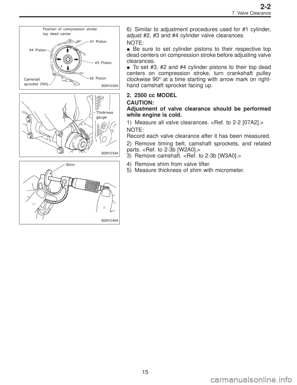
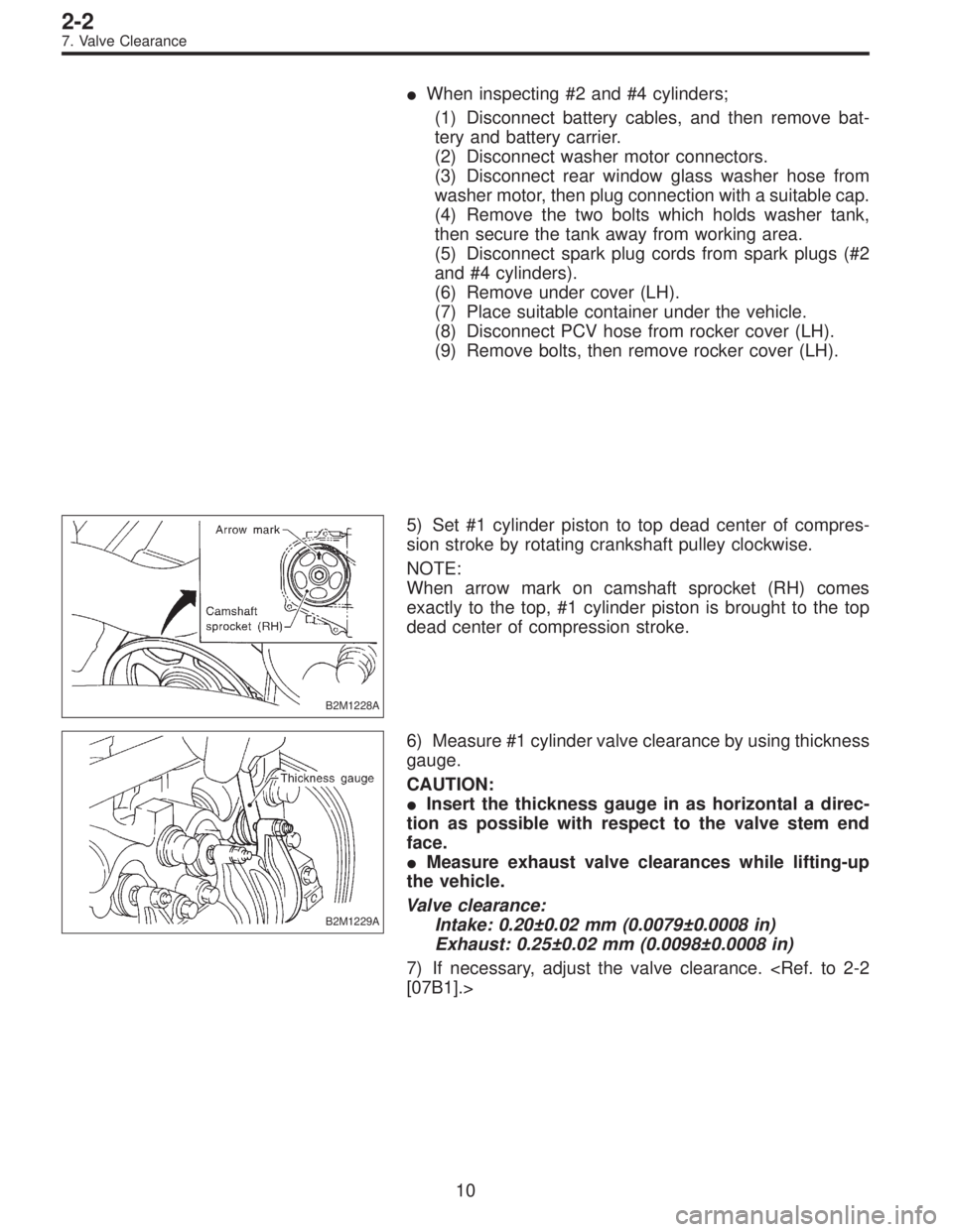
5) Set #1 cylinder piston to top dead center of compres-
sion stroke by rotating crankshaft pulley clockwise.
NOTE:
When arrow mark on camshaft sprocket (RH) comes
exactly to the top, #1 cylinder piston is brought to the top
dead center of compression stroke.
B2M1229A
6) Measure #1 cylinder valve clearance by using thickness
gauge.
CAUTION:
�Insert the thickness gauge in as horizontal a direc-
tion as possible with respect to the valve stem end
face.
�Measure exhaust valve clearances while lifting-up
the vehicle.
Valve clearance:
Intake: 0.20±0.02 mm (0.0079±0.0008 in)
Exhaust: 0.25±0.02 mm (0.0098±0.0008 in)
7) If necessary, adjust the valve clearance.
[07B1].>
10
2-2
7. Valve Clearance
Page 256 of 3342
B2M1230A
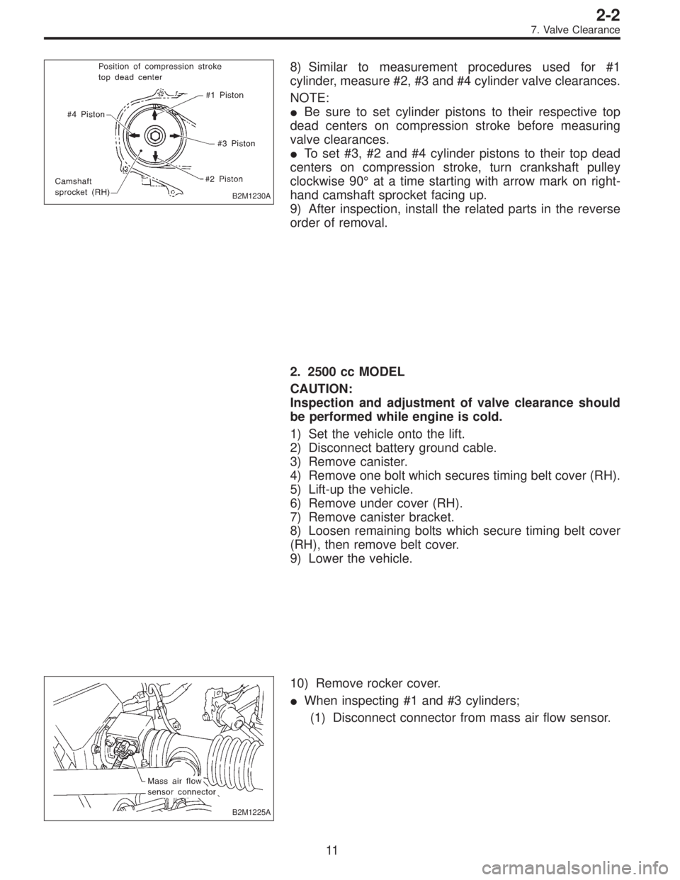
8) Similar to measurement procedures used for #1
cylinder, measure #2, #3 and #4 cylinder valve clearances.
NOTE:
�Be sure to set cylinder pistons to their respective top
dead centers on compression stroke before measuring
valve clearances.
�To set #3, #2 and #4 cylinder pistons to their top dead
centers on compression stroke, turn crankshaft pulley
clockwise 90°at a time starting with arrow mark on right-
hand camshaft sprocket facing up.
9) After inspection, install the related parts in the reverse
order of removal.
2. 2500 cc MODEL
CAUTION:
Inspection and adjustment of valve clearance should
be performed while engine is cold.
1) Set the vehicle onto the lift.
2) Disconnect battery ground cable.
3) Remove canister.
4) Remove one bolt which secures timing belt cover (RH).
5) Lift-up the vehicle.
6) Remove under cover (RH).
7) Remove canister bracket.
8) Loosen remaining bolts which secure timing belt cover
(RH), then remove belt cover.
9) Lower the vehicle.
B2M1225A
10) Remove rocker cover.
�When inspecting #1 and #3 cylinders;
(1) Disconnect connector from mass air flow sensor.
11
2-2
7. Valve Clearance
Page 258 of 3342
B2M1233A
B2M1234A
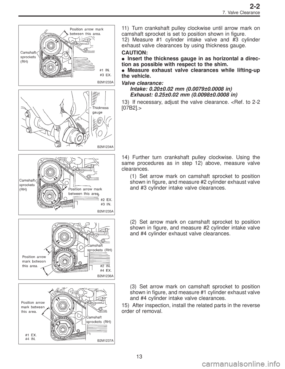
11) Turn crankshaft pulley clockwise until arrow mark on
camshaft sprocket is set to position shown in figure.
12) Measure #1 cylinder intake valve and #3 cylinder
exhaust valve clearances by using thickness gauge.
CAUTION:
�Insert the thickness gauge in as horizontal a direc-
tion as possible with respect to the shim.
�Measure exhaust valve clearances while lifting-up
the vehicle.
Valve clearance:
Intake: 0.20±0.02 mm (0.0079±0.0008 in)
Exhaust: 0.25±0.02 mm (0.0098±0.0008 in)
13) If necessary, adjust the valve clearance.
[07B2].>
B2M1235A
14) Further turn crankshaft pulley clockwise. Using the
same procedures as in step 12) above, measure valve
clearances.
(1) Set arrow mark on camshaft sprocket to position
shown in figure, and measure #2 cylinder exhaust valve
and #3 cylinder intake valve clearances.
B2M1236A
(2) Set arrow mark on camshaft sprocket to position
shown in figure, and measure #2 cylinder intake valve
and #4 cylinder exhaust valve clearances.
B2M1237A
(3) Set arrow mark on camshaft sprocket to position
shown in figure, and measure #1 cylinder exhaust valve
and #4 cylinder intake valve clearances.
15) After inspection, install the related parts in the reverse
order of removal.
13
2-2
7. Valve Clearance
Page 259 of 3342
B2M1228A
B: ADJUSTMENT
1. 2200 cc MODEL
CAUTION:
Adjustment of valve clearance should be performed
while engine is cold.
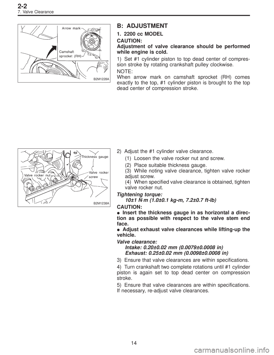
1) Set #1 cylinder piston to top dead center of compres-
sion stroke by rotating crankshaft pulley clockwise.
NOTE:
When arrow mark on camshaft sprocket (RH) comes
exactly to the top, #1 cylinder piston is brought to the top
dead center of compression stroke.
B2M1238A
2) Adjust the #1 cylinder valve clearance.
(1) Loosen the valve rocker nut and screw.
(2) Place suitable thickness gauge.
(3) While noting valve clearance, tighten valve rocker
adjust screw.
(4) When specified valve clearance is obtained, tighten
valve rocker nut.
Tightening torque:
10±1 N⋅m (1.0±0.1 kg-m, 7.2±0.7 ft-lb)
CAUTION:
�Insert the thickness gauge in as horizontal a direc-
tion as possible with respect to the valve stem end
face.
�Adjust exhaust valve clearances while lifting-up the
vehicle.
Valve clearance:
Intake: 0.20±0.02 mm (0.0079±0.0008 in)
Exhaust: 0.25±0.02 mm (0.0098±0.0008 in)
3) Ensure that valve clearances are within specifications.
4) Turn crankshaft two complete rotations until #1 cylinder
piston is again set to top dead center on compression
stroke.
5) Ensure that valve clearances are within specifications.
If necessary, re-adjust valve clearances.
14
2-2
7. Valve Clearance
Page 260 of 3342
B2M1230A
6) Similar to adjustment procedures used for #1 cylinder,
adjust #2, #3 and #4 cylinder valve clearances.
NOTE:
�Be sure to set cylinder pistons to their respective top
dead centers on compression stroke before adjusting valve
clearances.
�To set #3, #2 and #4 cylinder pistons to their top dead
centers on compression stroke, turn crankshaft pulley
clockwise 90°at a time starting with arrow mark on right-
hand camshaft sprocket facing up.
B2M1234A
2. 2500 cc MODEL
CAUTION:
Adjustment of valve clearance should be performed
while engine is cold.
1) Measure all valve clearances.
NOTE:
Record each valve clearance after it has been measured.
2) Remove timing belt, camshaft sprockets, and related
parts.
3) Remove camshaft.
B2M1240A
4) Remove shim from valve lifter.
5) Measure thickness of shim with micrometer.
15
2-2
7. Valve Clearance
Page 262 of 3342

B2M1233A
B2M1234A
10) Turn crankshaft pulley clockwise until arrow mark on
camshaft sprocket is set to position shown in figure.
11) Ensure that #1 cylinder intake valve and #3 cylinder
exhaust valve are adjusted to specifications.
CAUTION:
�Insert the thickness gauge in as horizontal a direc-
tion as possible with respect to the shim.
�Adjust exhaust valve clearances while lifting-up the
vehicle.
Valve clearance:
Intake: 0.20±0.02 mm (0.0079±0.0008 in)
Exhaust: 0.25±0.02 mm (0.0098±0.0008 in)
12) Turn crankshaft two complete rotations. Check again
to ensure that #1 cylinder intake valve and #3 cylinder
exhaust valve clearances are within specifications. If
necessary, re-adjust valve clearances.
B2M1235A
13) Further turn crankshaft pulley clockwise. Using the
same procedures as in step 11) above, measure valve
clearances.
(1) Set arrow mark on camshaft sprocket to position
shown in figure, and check #2 cylinder exhaust valve
and #3 cylinder intake valve clearances.
B2M1236A
(2) Set arrow mark on camshaft sprocket to position
shown in figure, and check #2 cylinder intake valve and
#4 cylinder exhaust valve clearances.
B2M1237A
(3) Set arrow mark on camshaft sprocket to position
shown in figure, and check #1 cylinder exhaust valve
and #4 cylinder intake valve clearances.
17
2-2
7. Valve Clearance
Page 265 of 3342
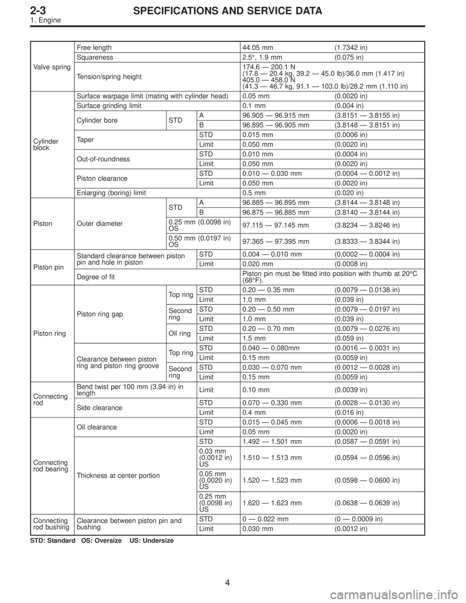
Valve springFree length 44.05 mm (1.7342 in)
Squareness 2.5°, 1.9 mm (0.075 in)
Tension/spring height174.6—200.1 N
(17.8—20.4 kg, 39.2—45.0 lb)/36.0 mm (1.417 in)
405.0—458.0 N
(41.3—46.7 kg, 91.1—103.0 lb)/28.2 mm (1.110 in)
Cylinder
blockSurface warpage limit (mating with cylinder head) 0.05 mm (0.0020 in)
Surface grinding limit 0.1 mm (0.004 in)
Cylinder bore STDA 96.905—96.915 mm (3.8151—3.8155 in)
B 96.895—96.905 mm (3.8148—3.8151 in)
TaperSTD 0.015 mm (0.0006 in)
Limit 0.050 mm (0.0020 in)
Out-of-roundnessSTD 0.010 mm (0.0004 in)
Limit 0.050 mm (0.0020 in)
Piston clearanceSTD 0.010—0.030 mm (0.0004—0.0012 in)
Limit 0.050 mm (0.0020 in)
Enlarging (boring) limit 0.5 mm (0.020 in)
Piston Outer diameterSTDA 96.885—96.895 mm (3.8144—3.8148 in)
B 96.875—96.885 mm (3.8140—3.8144 in)
0.25 mm (0.0098 in)
OS97.115—97.145 mm (3.8234—3.8246 in)
0.50 mm (0.0197 in)
OS97.365—97.395 mm (3.8333—3.8344 in)
Piston pinStandard clearance between piston
pin and hole in pistonSTD 0.004—0.010 mm (0.0002—0.0004 in)
Limit 0.020 mm (0.0008 in)
Degree of fitPiston pin must be fitted into position with thumb at 20°C
(68°F).
Piston ringPiston ring gapTop ringSTD 0.20—0.35 mm (0.0079—0.0138 in)
Limit 1.0 mm (0.039 in)
Second
ringSTD 0.20—0.50 mm (0.0079—0.0197 in)
Limit 1.0 mm (0.039 in)
Oil ringSTD 0.20—0.70 mm (0.0079—0.0276 in)
Limit 1.5 mm (0.059 in)
Clearance between piston
ring and piston ring grooveTop ringSTD 0.040—0.080mm (0.0016—0.0031 in)
Limit 0.15 mm (0.0059 in)
Second
ringSTD 0.030—0.070 mm (0.0012—0.0028 in)
Limit 0.15 mm (0.0059 in)
Connecting
rodBend twist per 100 mm (3.94 in) in
lengthLimit 0.10 mm (0.0039 in)
Side clearanceSTD 0.070—0.330 mm (0.0028—0.0130 in)
Limit 0.4 mm (0.016 in)
Connecting
rod bearingOil clearanceSTD 0.015—0.045 mm (0.0006—0.0018 in)
Limit 0.05 mm (0.0020 in)
Thickness at center portionSTD 1.492—1.501 mm (0.0587—0.0591 in)
0.03 mm
(0.0012 in)
US1.510—1.513 mm (0.0594—0.0596 in)
0.05 mm
(0.0020 in)
US1.520—1.523 mm (0.0598—0.0600 in)
0.25 mm
(0.0098 in)
US1.620—1.623 mm (0.0638—0.0639 in)
Connecting
rod bushingClearance between piston pin and
bushingSTD 0—0.022 mm (0—0.0009 in)
Limit 0.030 mm (0.0012 in)
STD: Standard OS: Oversize US: Undersize
4
2-3SPECIFICATIONS AND SERVICE DATA
1. Engine