Page 1033 of 3342
B3M0010
E: INSTALLATION
1) Put into gearshift lever from passenger compartment.
2) Mount boot plate on the body.
3) Install console box and gearshift knob.
[W1B0].>
G3M0684
4) Mount cushion rubber on the body.
Tightening torque:
18±5 N⋅m (1.84±0.51 kg-m, 13.3±3.7 ft-lb)
B3M0616A
5) Connect rod to the joint.
Tightening torque:
FWD model
12±3 N⋅m (1.2±0.3 kg-m, 8.7±2.2 ft-lb)
AWD model
18±5 N⋅m (1.84±0.51 kg-m, 13.3±3.7 ft-lb)
G3M0681
6) Connect stay to the bracket.
Tightening torque:
18±5 N⋅m (1.84±0.51 kg-m, 13.3±3.7 ft-lb)
7) Install the exhaust cover.
10
3-3SERVICE PROCEDURE
1. Manual Transmission
Page 1090 of 3342
 Loosen the left and right side steering tie-rods lock nuts.
2) Turn the left and right tie rods equal amounts until the
toe-in is at the specification.
Both the left and right t")
G4M0482
�Adjustment
1) Loosen the left and right side steering tie-rods lock nuts.
2) Turn the left and right tie rods equal amounts until the
toe-in is at the specification.
Both the left and right tie-rods are right-hand threaded. To
increase toe-in, turn both tie-rods clockwise equal amounts
(as viewed from the inside of the vehicle).
3) Tighten tie-rod lock nut.
Tightening torque:
83±5 N⋅m (8.5±0.5 kg-m, 61.5±3.6 ft-lb)
CAUTION:
Correct tie-rod boot, if it is twisted.
NOTE:
Check the left and right wheel steering angle is within
specifications.
M4A0059
4. REAR WHEEL TOE-IN (FWD MODEL)
�Inspection
1) Using a toe-in gauge, measure rear wheel toe-in.
Toe-in: 0±3 mm (0±0.12 in)
2) Mark rear sides of left and right tires at height corre-
sponding to center of spindles and measure distance“B”
between marks.
3) Move vehicle forward so that marks line up with front
sides at height corresponding to center of spindles.
4) Measure distance“A”between left and right marks.
Toe-in can then be obtained by the following equation:
B�A = Toe-in
G4M0483
�Adjustment
1) Remove cap from lateral link and loosen self-locking
nut.
CAUTION:
�When loosening or tightening adjusting bolt, hold
the bolt head and loosen self-locking nut.
�Replace self-locking nut with a new one.
2) Using two wrenches, turn adjusting wheel and adjusting
bolt equally in opposite directions so that toe-in is at the
specification.
11
4-1SERVICE PROCEDURE
1. On-car Services
Page 1094 of 3342
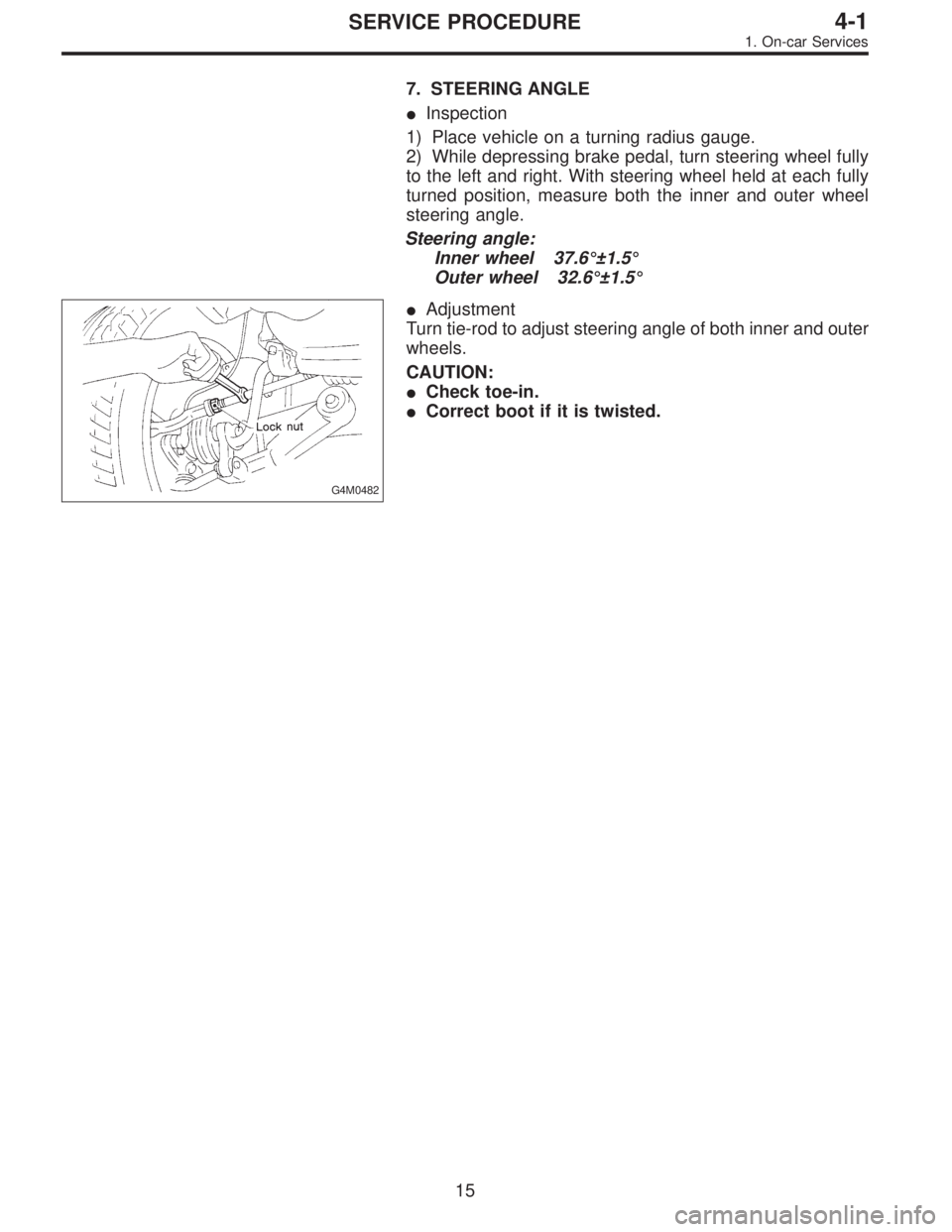
7. STEERING ANGLE
�Inspection
1) Place vehicle on a turning radius gauge.
2) While depressing brake pedal, turn steering wheel fully
to the left and right. With steering wheel held at each fully
turned position, measure both the inner and outer wheel
steering angle.
Steering angle:
Inner wheel 37.6°±1.5°
Outer wheel 32.6°±1.5°
G4M0482
�Adjustment
Turn tie-rod to adjust steering angle of both inner and outer
wheels.
CAUTION:
�Check toe-in.
�Correct boot if it is twisted.
15
4-1SERVICE PROCEDURE
1. On-car Services
Page 1107 of 3342
 Disconnect ground cable from battery.
2) Loosen front wheel nuts.
3) Lift-up vehicle, and remove front tires and wheels.
4) Remove both stabilizer and jack-u")
G4M0520
6. Front Crossmember
A: REMOVAL
1) Disconnect ground cable from battery.
2) Loosen front wheel nuts.
3) Lift-up vehicle, and remove front tires and wheels.
4) Remove both stabilizer and jack-up plate.
5) Disconnect tie-rod end from housing.
6) Remove front exhaust pipe.
G4M0521
7) Remove front transverse link from front crossmember
and body.
8) Remove nuts attaching engine mount cushion rubber to
crossmember.
9) Remove self-locking nuts connecting steering U/J and
pinion shaft.
10) Lift engine by approx. 10 mm (0.39 in) by using chain
block.
11) Support crossmember with a jack, remove nuts secur-
ing crossmember to body and lower crossmember gradu-
ally along with steering gearbox.
CAUTION:
When removing crossmember downward, be careful
that tie-rod end does not interfere with DOJ boot.
B: INSTALLATION
1) Installation is in the reverse order of removal proce-
dures.
CAUTION:
Always tighten rubber bushing when wheels are in full
contact with the ground and vehicle is at curb weight
condition.
Tightening torque:
Transverse link bushing to crossmember:
98±15 N⋅m (10.0±1.5 kg-m, 72±11 ft-lb)
Stabilizer to bushing:
25±4 N⋅m (2.5±0.4 kg-m, 18.1±2.9 ft-lb)
Tie-rod end to housing:
27.0±2.5 N⋅m (2.75±0.25 kg-m, 19.9±1.8 ft-lb)
Front cushion rubber to crossmember:
69±15 N⋅m (7.0±1.5 kg-m, 51±11 ft-lb)
Universal joint to pinion shaft:
24±3 N⋅m (2.4±0.3 kg-m, 17.4±2.2 ft-lb)
Crossmember to body:
98±15 N⋅m (10.0±1.5 kg-m, 72±11 ft-lb)
2) Purge air from power steering system.
NOTE:
Check wheel alignment and adjust if necessary.
28
4-1SERVICE PROCEDURE
6. Front Crossmember
Page 1130 of 3342
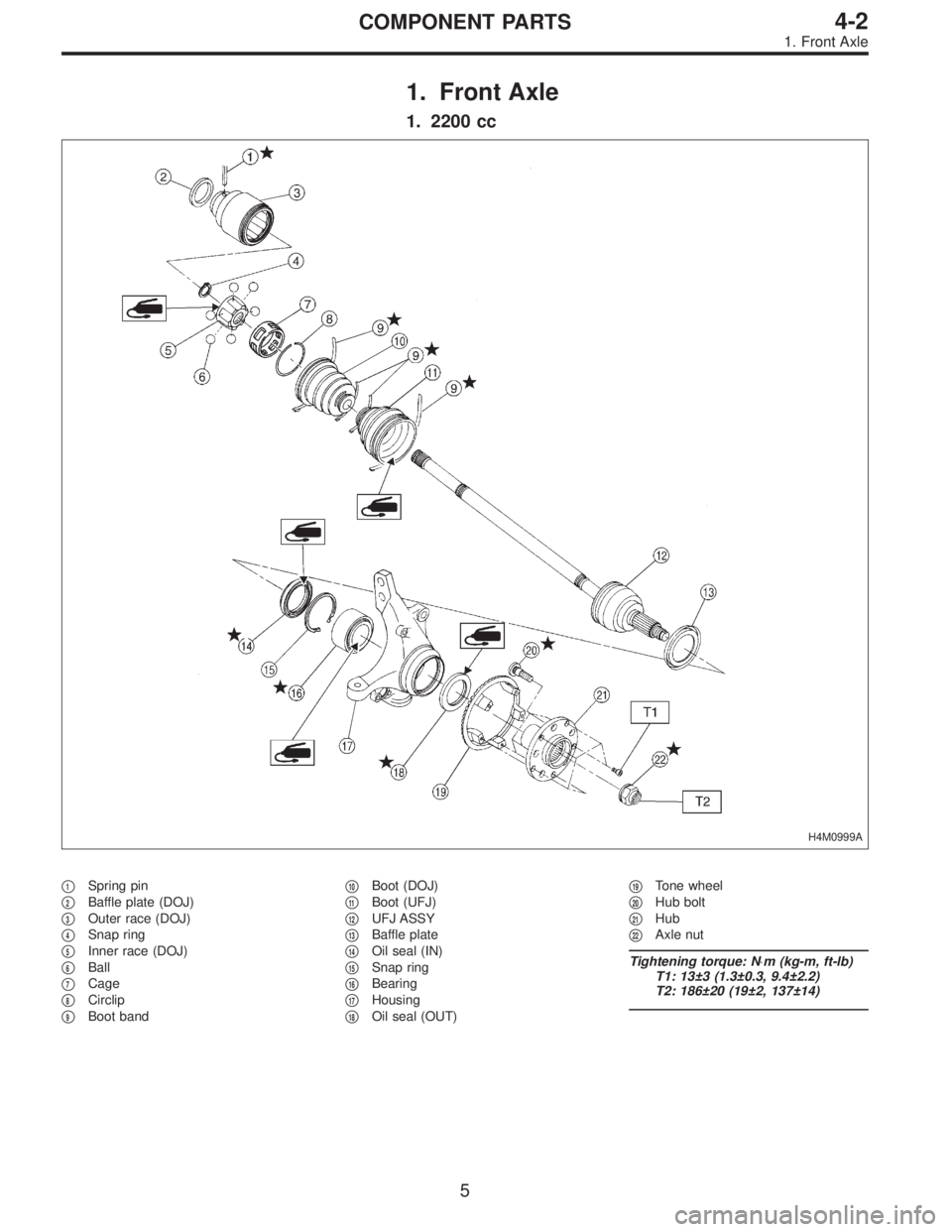
1. Front Axle
1. 2200 cc
H4M0999A
�1Spring pin
�
2Baffle plate (DOJ)
�
3Outer race (DOJ)
�
4Snap ring
�
5Inner race (DOJ)
�
6Ball
�
7Cage
�
8Circlip
�
9Boot band�
10Boot (DOJ)
�
11Boot (UFJ)
�
12UFJ ASSY
�
13Baffle plate
�
14Oil seal (IN)
�
15Snap ring
�
16Bearing
�
17Housing
�
18Oil seal (OUT)�
19Tone wheel
�
20Hub bolt
�
21Hub
�
22Axle nut
Tightening torque: N⋅m (kg-m, ft-lb)
T1: 13±3 (1.3±0.3, 9.4±2.2)
T2: 186±20 (19±2, 137±14)
5
4-2COMPONENT PARTS
1. Front Axle
Page 1131 of 3342
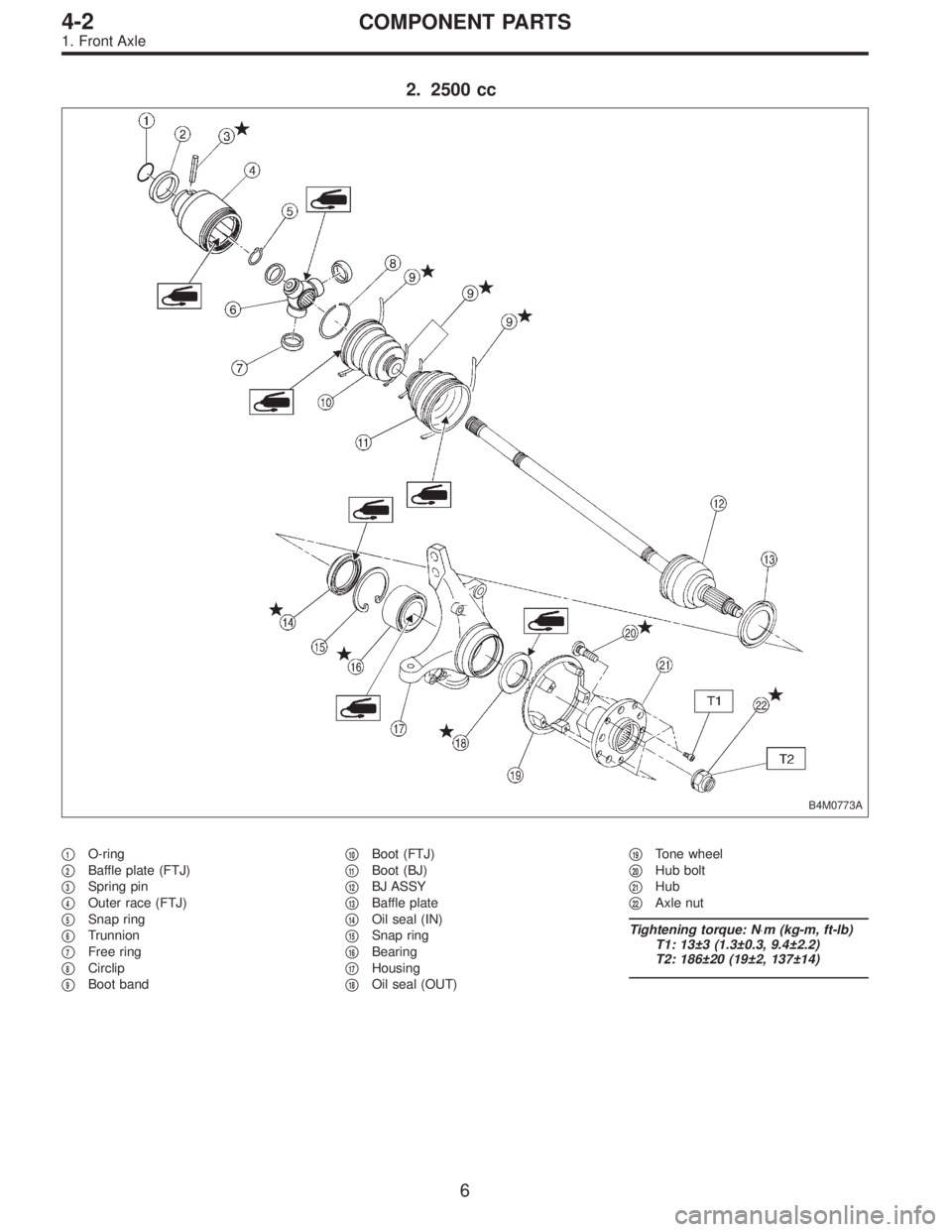
2. 2500 cc
B4M0773A
�1O-ring
�
2Baffle plate (FTJ)
�
3Spring pin
�
4Outer race (FTJ)
�
5Snap ring
�
6Trunnion
�
7Free ring
�
8Circlip
�
9Boot band�
10Boot (FTJ)
�
11Boot (BJ)
�
12BJ ASSY
�
13Baffle plate
�
14Oil seal (IN)
�
15Snap ring
�
16Bearing
�
17Housing
�
18Oil seal (OUT)�
19Tone wheel
�
20Hub bolt
�
21Hub
�
22Axle nut
Tightening torque: N⋅m (kg-m, ft-lb)
T1: 13±3 (1.3±0.3, 9.4±2.2)
T2: 186±20 (19±2, 137±14)
6
4-2COMPONENT PARTS
1. Front Axle
Page 1132 of 3342
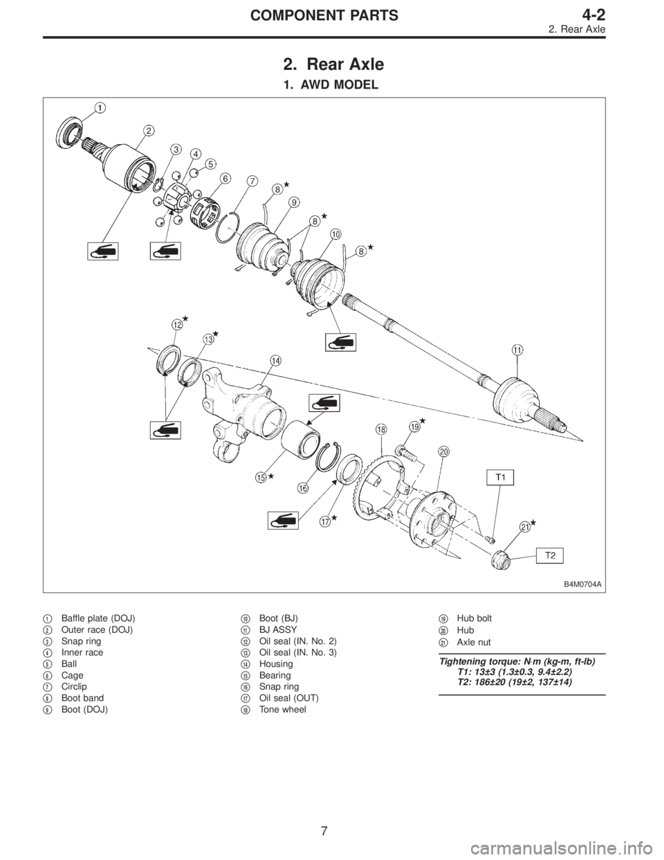
2. Rear Axle
1. AWD MODEL
B4M0704A
�1Baffle plate (DOJ)
�
2Outer race (DOJ)
�
3Snap ring
�
4Inner race
�
5Ball
�
6Cage
�
7Circlip
�
8Boot band
�
9Boot (DOJ)�
10Boot (BJ)
�
11BJ ASSY
�
12Oil seal (IN. No. 2)
�
13Oil seal (IN. No. 3)
�
14Housing
�
15Bearing
�
16Snap ring
�
17Oil seal (OUT)
�
18Tone wheel�
19Hub bolt
�
20Hub
�
21Axle nut
Tightening torque: N⋅m (kg-m, ft-lb)
T1: 13±3 (1.3±0.3, 9.4±2.2)
T2: 186±20 (19±2, 137±14)
7
4-2COMPONENT PARTS
2. Rear Axle
Page 1157 of 3342
 Remove axl")
G4M0995
CAUTION:
Be careful not to damage side bearing retainer. Always
use bolt as shown in figure, as supporting point for ST
during removal.
ST 28099PA100 DRIVE SHAFT REMOVER
G4M0247
10) Remove axle nut and drive shaft. If it is hard to
remove, use ST1 and ST2.
ST1 926470000 AXLE SHAFT PULLER
ST2 927140000 PLATE
CAUTION:
�Be careful not to damage oil seal lip when removing
rear drive shaft.
�When rear drive shaft is to be replaced, also replace
inner oil seal with a new one.
G4M0281
B: DISASSEMBLY
1. AWD MODEL
1) Straighten bent claw of larger end of DOJ boot.
2) Loosen band by means of screwdriver or pliers with
care of not damaging boot.
3) Remove boot band on the small end of DOJ boot in the
same manner.
4) Remove the larger end of DOJ boot from DOJ outer
race.
G4M0282
5) Pry and remove round circlip located at the neck of DOJ
outer race with a screwdriver.
B4M0227A
6) Take out DOJ outer race from shaft assembly.
7) Wipe off grease and take out balls.
CAUTION:
The grease is a special grease (grease for constant
velocity joint). Do not confuse with other greases.
NOTE:
Disassemble exercising care not to lose balls (6 pcs).
�
1Outer race
�
2Grease
30
4-2SERVICE PROCEDURE
4. Front and Rear Drive Shafts
![SUBARU LEGACY 1997 Service Repair Manual B3M0010
E: INSTALLATION
1) Put into gearshift lever from passenger compartment.
2) Mount boot plate on the body.
3) Install console box and gearshift knob. <Ref. to 5-4
[W1B0].>
G3M0684
4) Mount cushi](/manual-img/17/57434/w960_57434-1032.png "SUBARU LEGACY 1997 Service Repair Manual B3M0010
E: INSTALLATION
1) Put into gearshift lever from passenger compartment.
2) Mount boot plate on the body.
3) Install console box and gearshift knob. <Ref. to 5-4
[W1B0].>
G3M0684
4) Mount cushi")