Page 2406 of 3342
1. Supplemental Restraint System
“Airbag”
Airbag system wiring harness is routed near the transmis-
sion control module (TCM).
�All Airbag system wiring harness and connectors
are colored yellow. Do not use electrical test equip-
ment on these circuit.
�Be careful not to damage Airbag system wiring har-
ness when performing diagnostics and servicing the
TCM.
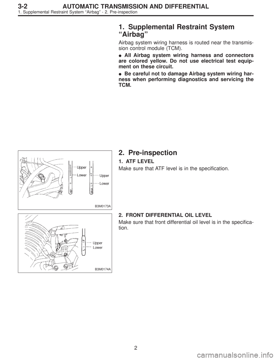
B3M0173A
2. Pre-inspection
1. ATF LEVEL
Make sure that ATF level is in the specification.
B3M0174A
2. FRONT DIFFERENTIAL OIL LEVEL
Make sure that front differential oil level is in the specifica-
tion.
2
3-2AUTOMATIC TRANSMISSION AND DIFFERENTIAL
1. Supplemental Restraint System“Airbag”- 2. Pre-inspection
Page 2407 of 3342
G3M0717
3. OPERATION OF SHIFT SELECTOR LEVER
WARNING:
Stop the engine while checking operation of selector
lever.
1) Check that selector lever does not move from“N”to“R”
without pushing the button.
2) Check that selector lever does not move from“R”to“P”
without pushing the button.
3) Check that selector lever does not move from“P”to“R”
without pushing the button.
4) Check that selector lever does not move from“3”to“2”
without pushing the button.
3
3-2AUTOMATIC TRANSMISSION AND DIFFERENTIAL
2. Pre-inspection
Page 2408 of 3342
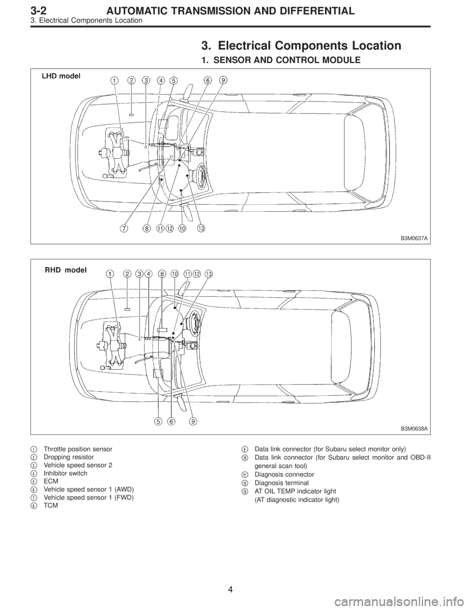
3. Electrical Components Location
1. SENSOR AND CONTROL MODULE
B3M0637A
B3M0638A
�1Throttle position sensor
�
2Dropping resistor
�
3Vehicle speed sensor 2
�
4Inhibitor switch
�
5ECM
�
6Vehicle speed sensor 1 (AWD)
�
7Vehicle speed sensor 1 (FWD)
�
8TCM�
9Data link connector (for Subaru select monitor only)
�
10Data link connector (for Subaru select monitor and OBD-II
general scan tool)
�
11Diagnosis connector
�
12Diagnosis terminal
�
13AT OIL TEMP indicator light
(AT diagnostic indicator light)
4
3-2AUTOMATIC TRANSMISSION AND DIFFERENTIAL
3. Electrical Components Location
Page 2409 of 3342
B2M0155AOBD0046A
B2M0211A
B3M0182C
B3M0183AB2M1043C
B3M0184AB3M0185A
5
3-2AUTOMATIC TRANSMISSION AND DIFFERENTIAL
3. Electrical Components Location
Page 2410 of 3342
B3M0443GB3M0445C
OBD0005COBD0006A
H3M1161AOBD0008D
6
3-2AUTOMATIC TRANSMISSION AND DIFFERENTIAL
3. Electrical Components Location
Page 2411 of 3342
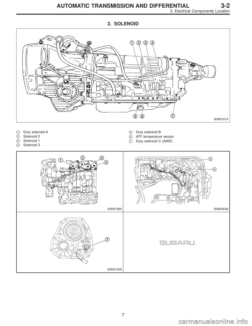
2. SOLENOID
B3M0187A
�1Duty solenoid A
�
2Solenoid 2
�
3Solenoid 1
�
4Solenoid 3�
5Duty solenoid B
�
6ATF temperature sensor
�
7Duty solenoid C (AWD)
B3M0188AB2M0464B
B3M0190A
7
3-2AUTOMATIC TRANSMISSION AND DIFFERENTIAL
3. Electrical Components Location
Page 2412 of 3342
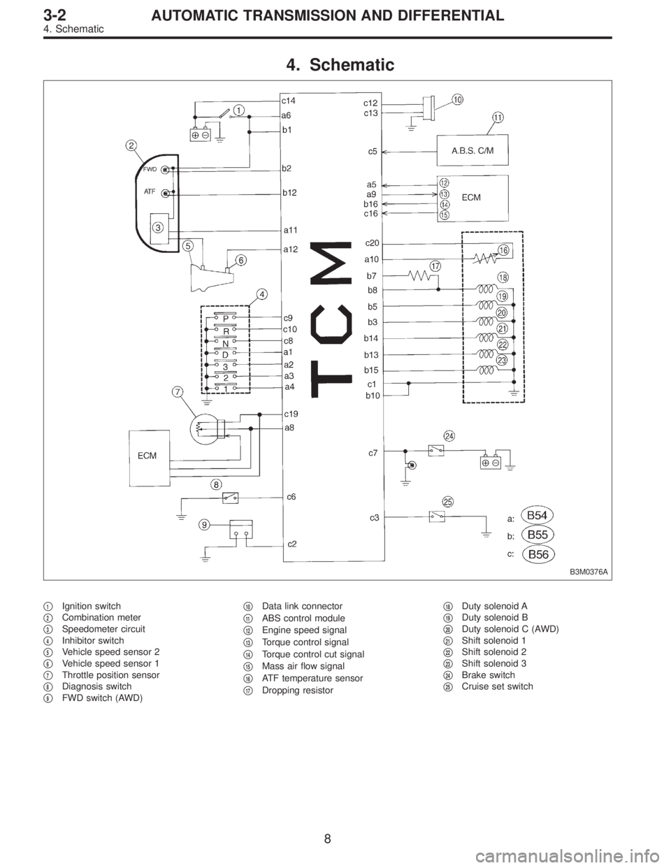
4. Schematic
B3M0376A
�1Ignition switch
�
2Combination meter
�
3Speedometer circuit
�
4Inhibitor switch
�
5Vehicle speed sensor 2
�
6Vehicle speed sensor 1
�
7Throttle position sensor
�
8Diagnosis switch
�
9FWD switch (AWD)�
10Data link connector
�
11ABS control module
�
12Engine speed signal
�
13Torque control signal
�
14Torque control cut signal
�
15Mass air flow signal
�
16ATF temperature sensor
�
17Dropping resistor�
18Duty solenoid A
�
19Duty solenoid B
�
20Duty solenoid C (AWD)
�
21Shift solenoid 1
�
22Shift solenoid 2
�
23Shift solenoid 3
�
24Brake switch
�
25Cruise set switch
8
3-2AUTOMATIC TRANSMISSION AND DIFFERENTIAL
4. Schematic
Page 2413 of 3342

I/O Signal
OBD0093A
Check with ignition switch ON.
ContentConnector
No.Terminal
No.Measuring conditions Voltage (V)
Back-up power supply B56 14 Ignition switch OFF")
5. Transmission Control Module (TCM)
I/O Signal
OBD0093A
Check with ignition switch ON.
ContentConnector
No.Terminal
No.Measuring conditions Voltage (V)
Back-up power supply B56 14 Ignition switch OFF 10—16
Ignition power supplyB54 6
Ignition switch ON (with engine OFF) 10—16
B55 1
Inhibitor switch“P”range switch B56 9Select lever in“P”range Less than 1
Select lever in any other than“P”
range (except“N”range)More than 8
“N”range switch B56 8Select lever in“N”range Less than 1
Select lever in any other than“N”
range (except“P”range)More than 8
“R”range switch B56 10Select lever in“R”range Less than 1
Select lever in any other than“R”
rangeMore than 6
“D”range switch B54 1Select lever in“D”range Less than 1
Select lever in any other than“D”
rangeMore than 6
“3”range switch B54 2Select lever in“3”range Less than 1
Select lever in any other than“3”
rangeMore than 6
“2”range switch B54 3Select lever in“2”range Less than 1
Select lever in any other than“2”
rangeMore than 6
“1”range switch B54 4Select lever in“1”range Less than 1
Select lever in any other than“1”
rangeMore than 6
Diagnosis switch B56 6Diagnosis connector connected Less than 1
Diagnosis connector disconnected More than 6
Brake switch B56 7Brake pedal depressed. More than 10.5
Brake pedal released. Less than 1
ABS signal B56 5ABS switch ON Less than 1
ABS switch OFF More than 6.5
AT diagnostic signal B55 12Ignition switch ON (With engine OFF) Less than 1
Ignition switch ON (With engine ON) More than 10
9
3-2AUTOMATIC TRANSMISSION AND DIFFERENTIAL
5. Transmission Control Module (TCM) I/O Signal
 Check that selector lever does not move from“N”to“R”
without pushing the bu")