Page 1172 of 3342
 Align DOJ and differential splines.
7) Push housing to insert DOJ into differential.
NOTE:
Make sure DOJ is inserted properly.
8) Connect crossmember reinforcement lower to cross-
member (4")
G3M0050
6) Align DOJ and differential splines.
7) Push housing to insert DOJ into differential.
NOTE:
Make sure DOJ is inserted properly.
8) Connect crossmember reinforcement lower to cross-
member (4 door model only).
9) Connect rear housing assembly to trailing link
assembly, and tighten self-locking nut.
Tightening torque:
113±15 N⋅m (11.5±1.5 kg-m, 83±11 ft-lb)
10) Connect rear housing assembly to lateral link
assembly, and tighten self-locking nut.
Tightening torque:
137±20 N⋅m (14±2 kg-m, 101±14 ft-lb)
11) Install stabilizer bracket.
12) While depressing brake pedal, tighten axle nut using
a socket wrench.
Tightening torque:
186±20 N⋅m (19±2 kg-m, 137±14 ft-lb)
CAUTION:
�Use a new axle nut.
�Always tighten axle nut before installing wheel on
vehicle. If wheel is installed and comes in contact with
ground when axle nut is loose, wheel bearings may be
damaged.
�Be sure to tighten axle nut to specified torque. Do
not overtighten it as this may damage wheel bearing.
13) After tightening axle nut, lock it securely.
45
4-2SERVICE PROCEDURE
4. Front and Rear Drive Shafts
Page 1174 of 3342
6. Replacement of Rear DOJ and BJ
Boots
A: REMOVAL
1) Disconnect ground cable from battery.
2) Lift-up vehicle, and remove rear wheel cap and wheels.
NOTE:
Axle nut need not be removed.
3) Remove A.B.S. sensor clamps and parking brake cable
bracket.
4) Disconnect stabilizer link from lateral link.
5) Remove bolts which secure lateral link assembly to rear
housing.
6) Remove bolts which secure trailing link assembly to
rear housing.
7) Remove crossmember reinforcement lower from cross-
member (4 door model only).
G4M0994
8) Remove DOJ from rear differential using ST.
ST 28099PA100 DRIVE SHAFT REMOVER
NOTE:
The side spline shaft circlip comes out together with the
shaft.
G4M0995
CAUTION:
Be careful not to damage side bearing retainer. Always
use bolt as shown in figure, as supporting point for ST
during removal.
ST 28099PA100 DRIVE SHAFT REMOVER
B: INSTALLATION
1) Install DOJ and BJ boots to drive shaft.
47
4-2SERVICE PROCEDURE
6. Replacement of Rear DOJ and BJ Boots
Page 1175 of 3342
B4M0549A
2) Using ST, install DOJ into differential.
ST 28099PA090 SIDE OIL SEAL PROTECTOR
B4M0550A
3) Insert DOJ spline end into bore of side oil seal, and
remove ST.
CAUTION:
Do not allow DOJ splines to damage side oil seal.
ST 28099PA090 SIDE OIL SEAL PROTECTOR
G3M0050
4) Align DOJ and differential splines.
5) Push housing to insert DOJ into differential.
NOTE:
Make sure DOJ is inserted properly.
CAUTION:
Discard old self-locking nut. Replace with a new one.
6) Connect rear housing assembly to trailing link
assembly, and tighten self-locking nut.
7) Connect rear housing assembly to lateral link assembly,
and tighten self-locking nut.
8) Connect stabilizer link to lateral link.
9) Install crossmember reinforcement lower to crossmem-
ber (4 door model only).
10) Install A.B.S. sensor clamps and parking brake cable
bracket.
48
4-2SERVICE PROCEDURE
6. Replacement of Rear DOJ and BJ Boots
Page 1936 of 3342
A: BASIC CHECK ITEMS FOR AT
When trouble code about automatic transmission is shown
on display, carry out the following basic check. After that,
carry out the replacement or repair work.
1) ATF level check
2) Differential gear oil level check
3) ATF leak check
4) Differential gear oil leak check
5) Brake band adjustment
6) Stall test
7) Line pressure test
8) Transfer clutch pressure test
9) Time lag test
10) Road test
11) Shift characteristics
NOTE:
As for the method, refer to 3-2 [W2A0], [W2B1], [W300].
85
2-7ON-BOARD DIAGNOSTICS II SYSTEM
6. Basic Diagnostic Procedure
Page 1977 of 3342

One-way clutch (3-")
Overrunning clutch
Drive pinion
Crown gear
Axle shaft
Differential gear
Final gear
Seal pipe
Oil pump
High clutch
Band brake
Low & reverse clutch
Reverse clutch
One-way clutch (1-2)
One-way clutch (3-4)
Double oil seal
Input shaft
Output shaft
Planetary gear
Reduction gear
Drive plate
Torque converter one-way clutch
Lock-up facing
Lock-up damper
ATF deterioration
ATF level too high or too low
Differential gear oil level too high or too low
Engine performance
Engine speed signal
Parking brake mechanism
Problem parts
30 31 32 33 34 35 36 37 38 39 40 41 42 43 44 45 46 47 48 49 50 51 52 53 54 55 56 57 58 Symptom
Starter does not rotate when select lever is
in“P”or“N.”; starter rotates when select
lever is“R”,“D”,“3”or“2.”
���Abnormal noise when select lever is in“P”or
“N.”
�Hissing noise occurs during standing starts.
����Noise occurs while driving in“D
1”range.
����Noise occurs while driving in“D
2”range.
���Noise occurs while driving in“D
3”range.
����Noise occurs while driving in“D
4”range.
��Engine stalls while shifting from one range to
another.
Vehicle moves when select lever is in“N.”
�Shock occurs when select lever is moved
from“N”to“D.”
Excessive time lag occurs when select lever
is moved from“N”to“D.”
�Shock occurs when select lever is moved
from“N”to“R.”
��Excessive time lag occurs when select lever
is moved from“N”to“R.”
���� � ��� � �Vehicle does not start in any shift range
(engine revving up).
�Vehicle does not start in any shift range
(engine stall).
��Vehicle does not start in“R”range only
(engine revving up).
��Vehicle does not start in“R”range only
(engine stall).
�Vehicle does not start in“D”or“3”range
(engine revving up).
Vehicle does not start in“D”,“3”or“2”range
(engine revving up).
�Vehicle does not start in“D”,“3”or“2”range
(engine stall).
Vehicle starts in“R”range only (engine rev-
ving up).
��Acceleration during standing starts is poor
(high stall rpm).
���Acceleration during standing starts is poor
(low stall rpm).
�� �Acceleration is poor when select lever is in
“D”,“3”or“2”range (normal stall rpm).
����Acceleration is poor when select lever is in
“R”(normal stall rpm).
�No shift occurs from 1st to 2nd gear.
��No shift occurs from 2nd to 3rd gear.
�No shift occurs from 3rd to 4th gear.
No“kick-down”shifts occur.
Engine brake is not effected when select
lever is in“3”range.
30 31 32 33 34 35 36 37 38 39 40 41 42 43 44 45 46 47 48 49 50 51 52 53 54 55 56 57 58
126
2-7ON-BOARD DIAGNOSTICS II SYSTEM
9. General Diagnostic Table
Page 1978 of 3342

Problem parts
Inhibitor switch
Control module
Vehicle speed sensor 1
Vehicle speed sensor 2
Select cable
Select lever
FWD switch
Starter motor and harness
Throttle position sensor
Hold switch
Accumulator (“N”—“D”)
Accumulator (2A)
Accumulator (4A)
Accumulator (3R)
ATF temperature sensor
Strainer
Duty solenoid A
Duty solenoid B
Shift solenoid 1
Shift solenoid 2
Shift solenoid 3
Control valve
Detent spring
Manual plate
Transfer clutch
Transfer valve
Transfer pipe
Duty solenoid C
Forward clutch
Symptom1234567891011121314151617181920212223242526272829
Engine brake is not effected when select
lever is in“3”or“2”range.
Engine brake is not effected when select
lever is in“1”range.�
Shift characteristics are erroneous.���� � �
No lock-up occurs.����
Vehicle cannot be set in“D”range power
mode.��
“D”range power mode cannot be released.���
Parking brake is not effected.��
Shift lever cannot be moved or is hard to
move from“P”range.��
Select lever is hard to move.�� ��
Select lever is too light to move (unreason-
able resistance).��
ATF spurts out.
Differential oil spurts out.
Differential oil level changes excessively.
Odor is produced from oil supply pipe.��
Shock occurs when select lever is moved
from“1”to“2”range.� ���� �
Slippage occurs when select lever is moved
from“1”to“2”range.� ���� �
Shock occurs when select lever is moved
from“2”to“3”range.������
Slippage occurs when select lever is moved
from“2”to“3”range.������
Shock occurs when select lever is moved
from“3”to“4”range.� � ��� �
Slippage occurs when select lever is moved
from“3”to“4”range.� � ��� �
Shock occurs when select lever is moved
from“3”to“2”range.�����
Shock occurs when select lever is moved
from“D”to“1”range.�����
Shock occurs when select lever is moved
from“2”to“1”range.�����
Shock occurs when accelerator pedal is
released at medium speeds.�����
Vibration occurs during straight-forward
operation.��
Select lever slips out of position during
acceleration or while driving on rough terrain.�� ��
Vibration occurs during turns (tight corner
“braking”phenomenon).��� �� � �� �
Front wheel slippage occurs during standing
starts.� � � �� � � ����
Vehicle is not set in FWD mode.�� ���
1234567891011121314151617181920212223242526272829
127
2-7ON-BOARD DIAGNOSTICS II SYSTEM
9. General Diagnostic Table
Page 1979 of 3342

One-way clutch (3-")
Overrunning clutch
Drive pinion
Crown gear
Axle shaft
Differential gear
Final gear
Seal pipe
Oil pump
High clutch
Band brake
Low & reverse clutch
Reverse clutch
One-way clutch (1-2)
One-way clutch (3-4)
Double oil seal
Input shaft
Output shaft
Planetary gear
Reduction gear
Drive plate
Torque converter one-way clutch
Lock-up facing
Lock-up damper
ATF deterioration
ATF level too high or too low
Differential gear oil level too high or too low
Engine performance
Engine speed signal
Parking brake mechanism
Problem parts
30 31 32 33 34 35 36 37 38 39 40 41 42 43 44 45 46 47 48 49 50 51 52 53 54 55 56 57 58 Symptom
�Engine brake is not effected when select
lever is in“3”or“2”range.
�Engine brake is not effected when select
lever is in“1”range.
Shift characteristics are erroneous.
��No lock-up occurs.
Vehicle cannot be set in“D”range power
mode.
“D”range power mode cannot be released.
�Parking brake is not effected.
�Shift lever cannot be moved or is hard to
move from“P”range.
Select lever is hard to move.
Select lever is too light to move (unreason-
able resistance).
�ATF spurts out.
�Differential oil spurts out.
��Differential oil level changes excessively.
� ���� � �Odor is produced from oil supply pipe.
���Shock occurs when select lever is moved
from“1”to“2”range.
�Slippage occurs when select lever is moved
from“1”to“2”range.
�� � �Shock occurs when select lever is moved
from“2”to“3”range.
��Slippage occurs when select lever is moved
from“2”to“3”range.
�� ��Shock occurs when select lever is moved
from“3”to“4”range.
�Slippage occurs when select lever is moved
from“3”to“4”range.
�� �Shock occurs when select lever is moved
from“3”to“2”range.
�Shock occurs when select lever is moved
from“D”to“1”range.
��Shock occurs when select lever is moved
from“2”to“1”range.
��Shock occurs when accelerator pedal is
released at medium speeds.
��Vibration occurs during straight-forward
operation.
Select lever slips out of position during
acceleration or while driving on rough terrain.
�Vibration occurs during turns (tight corner
“braking”phenomenon).
Front wheel slippage occurs during standing
starts.
Vehicle is not set in FWD mode.
30 31 32 33 34 35 36 37 38 39 40 41 42 43 44 45 46 47 48 49 50 51 52 53 54 55 56 57 58
128
2-7ON-BOARD DIAGNOSTICS II SYSTEM
9. General Diagnostic Table
Page 2405 of 3342
1. Supplemental Restraint System
“Airbag”
Airbag system wiring harness is routed near the transmis-
sion control module (TCM).
�All Airbag system wiring harness and connectors
are colored yellow. Do not use electrical test equip-
ment on these circuit.
�Be careful not to damage Airbag system wiring har-
ness when performing diagnostics and servicing the
TCM.
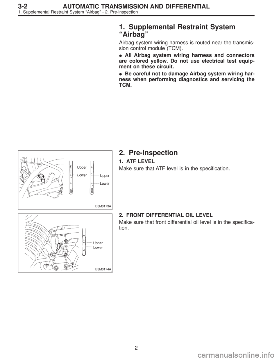
B3M0173A
2. Pre-inspection
1. ATF LEVEL
Make sure that ATF level is in the specification.
B3M0174A
2. FRONT DIFFERENTIAL OIL LEVEL
Make sure that front differential oil level is in the specifica-
tion.
2
3-2AUTOMATIC TRANSMISSION AND DIFFERENTIAL
1. Supplemental Restraint System“Airbag”- 2. Pre-inspection
 Disconnect ground cable from battery.
2) Lift-up vehicle, and remove rear wheel cap and wheels.
NOTE:
Axle nut need not be removed.
3) Remove A.B.")
 Using ST, install DOJ into differential.
ST 28099PA090 SIDE OIL SEAL PROTECTOR
B4M0550A
3) Insert DOJ spline end into bore of side oil seal, and
remove ST.
CAUTION:
Do not allow DOJ spline")
 ATF level")