Page 1529 of 3342
5. TRUNK LID AND REAR GATE
B5M0255A
Unit: mm (in)
20
5-1SERVICE DATA
3. Datum Dimensions
Page 1530 of 3342
6. COMPARTMENT
B5M0256A
Unit: mm (in)
21
5-1SERVICE DATA
3. Datum Dimensions
Page 1531 of 3342
4. Datum Points and Dimensions
Concerning On-Board Aiming
Adjustment
If headlight aiming is misaligned due to damaged body
panel, repair headlight mating surface using body and
headlight datum points as a guide.
NOTE:
It is recommended to conduct On-Board Aiming Adjust-
ment with headlights turned off.
If turned on during the adjustment, the duration should be
within two minutes.
B5M0364
Unit: mm (in)
22
5-1SERVICE DATA
4. Datum Points and Dimensions Concerning On-Board Aiming Adjustment
Page 1542 of 3342

1. Hood
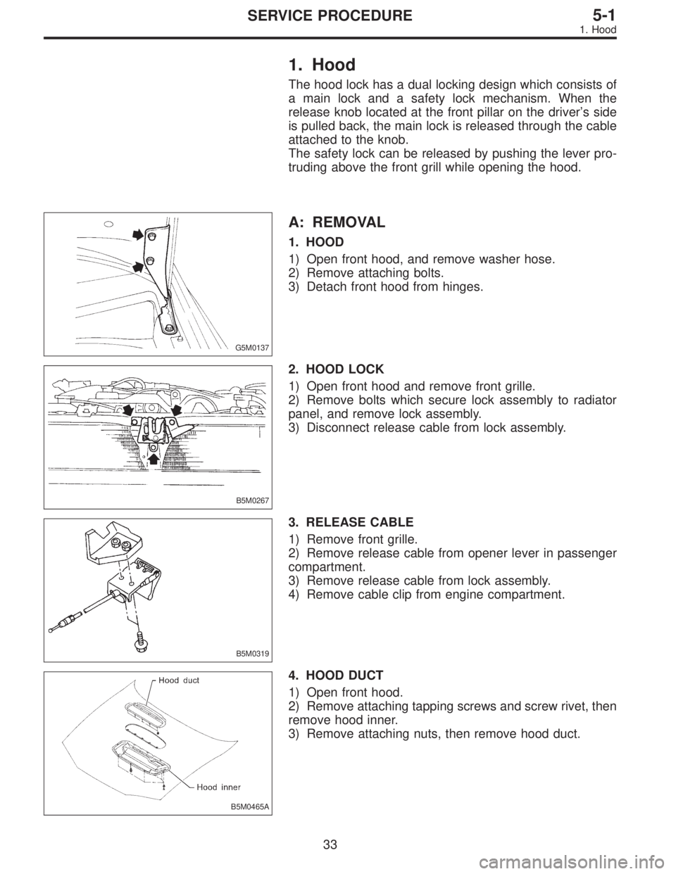
The hood lock has a dual locking design which consists of
a main lock and a safety lock mechanism. When the
release knob located at the front pillar on the driver’s side
is pulled back, the main lock is released through the cable
attached to the knob.
The safety lock can be released by pushing the lever pro-
truding above the front grill while opening the hood.
G5M0137
A: REMOVAL
1. HOOD
1) Open front hood, and remove washer hose.
2) Remove attaching bolts.
3) Detach front hood from hinges.
B5M0267
2. HOOD LOCK
1) Open front hood and remove front grille.
2) Remove bolts which secure lock assembly to radiator
panel, and remove lock assembly.
3) Disconnect release cable from lock assembly.
B5M0319
3. RELEASE CABLE
1) Remove front grille.
2) Remove release cable from opener lever in passenger
compartment.
3) Remove release cable from lock assembly.
4) Remove cable clip from engine compartment.
B5M0465A
4. HOOD DUCT
1) Open front hood.
2) Remove attaching tapping screws and screw rivet, then
remove hood inner.
3) Remove attaching nuts, then remove hood duct.
33
5-1SERVICE PROCEDURE
1. Hood
Page 1543 of 3342

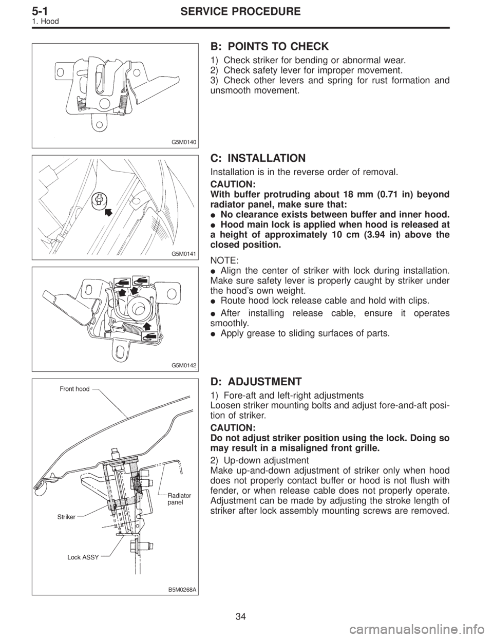
G5M0140
B: POINTS TO CHECK
1) Check striker for bending or abnormal wear.
2) Check safety lever for improper movement.
3) Check other levers and spring for rust formation and
unsmooth movement.
G5M0141
C: INSTALLATION
Installation is in the reverse order of removal.
CAUTION:
With buffer protruding about 18 mm (0.71 in) beyond
radiator panel, make sure that:
�No clearance exists between buffer and inner hood.
�Hood main lock is applied when hood is released at
a height of approximately 10 cm (3.94 in) above the
closed position.
G5M0142
NOTE:
�Align the center of striker with lock during installation.
Make sure safety lever is properly caught by striker under
the hood’s own weight.
�Route hood lock release cable and hold with clips.
�After installing release cable, ensure it operates
smoothly.
�Apply grease to sliding surfaces of parts.
B5M0268A
D: ADJUSTMENT
1) Fore-aft and left-right adjustments
Loosen striker mounting bolts and adjust fore-and-aft posi-
tion of striker.
CAUTION:
Do not adjust striker position using the lock. Doing so
may result in a misaligned front grille.
2) Up-down adjustment
Make up-and-down adjustment of striker only when hood
does not properly contact buffer or hood is not flush with
fender, or when release cable does not properly operate.
Adjustment can be made by adjusting the stroke length of
striker after lock assembly mounting screws are removed.
34
5-1SERVICE PROCEDURE
1. Hood
Page 1544 of 3342
G5M0144
2. Trunk Lid
A: REMOVAL
1. TRUNK LID
1) Open trunk lid.
2) Remove trunk lid mounting bolts and detach trunk lid
from hinges.
G5M0145
2. TORSION BAR
1) Open trunk lid. Remove torsion bars from hinge links
using ST.
ST 927780000 REMOVER
CAUTION:
Be careful because torsion bar quickly swings back
when released.
2) Remove the left and right torsion bars.
WARNING:
Be careful because trunk lid drops under its own
weight when torsion bars are removed.
G5M0146
3. TRUNK LID LOCK ASSEMBLY AND KEY
CYLINDER
1) Remove rod of lock assembly from rod holder of key
lock assembly.
2) Remove nuts which hold lock assembly and remove
lock assembly.
NOTE:
�Always remove rear skirt trim panel beforehand, if so
equipped.
�Be careful not to bend opener cable.
B5M0269A
3) Remove rod holder and detach key cylinder from trunk
lid.
35
5-1SERVICE PROCEDURE
2. Trunk Lid
Page 1545 of 3342

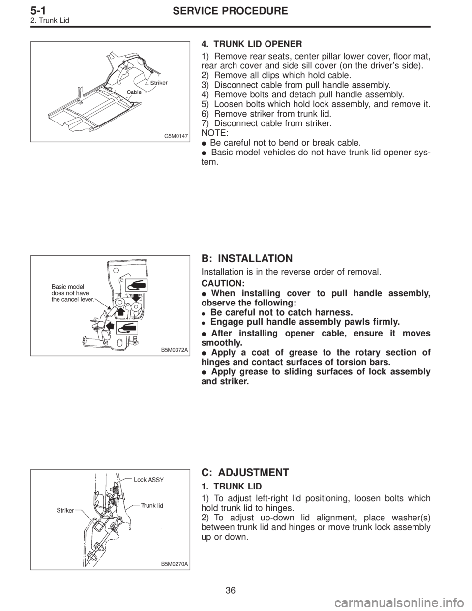
G5M0147
4. TRUNK LID OPENER
1) Remove rear seats, center pillar lower cover, floor mat,
rear arch cover and side sill cover (on the driver’s side).
2) Remove all clips which hold cable.
3) Disconnect cable from pull handle assembly.
4) Remove bolts and detach pull handle assembly.
5) Loosen bolts which hold lock assembly, and remove it.
6) Remove striker from trunk lid.
7) Disconnect cable from striker.
NOTE:
�Be careful not to bend or break cable.
�Basic model vehicles do not have trunk lid opener sys-
tem.
B5M0372A
B: INSTALLATION
Installation is in the reverse order of removal.
CAUTION:
�When installing cover to pull handle assembly,
observe the following:
�Be careful not to catch harness.
�Engage pull handle assembly pawls firmly.
�After installing opener cable, ensure it moves
smoothly.
�Apply a coat of grease to the rotary section of
hinges and contact surfaces of torsion bars.
�Apply grease to sliding surfaces of lock assembly
and striker.
B5M0270A
C: ADJUSTMENT
1. TRUNK LID
1) To adjust left-right lid positioning, loosen bolts which
hold trunk lid to hinges.
2) To adjust up-down lid alignment, place washer(s)
between trunk lid and hinges or move trunk lock assembly
up or down.
36
5-1SERVICE PROCEDURE
2. Trunk Lid
Page 1546 of 3342
B5M0373
3. Fuel Flap
A: REMOVAL
1. FUEL FLAP
Remove bolts which hold hinge to fuel flap, and detach fuel
flap.
B5M0374A
2. FUEL FLAP OPENER
1) Remove rear seats, center pillar lower cover, floor mat,
rear arch cover/rear quarter trim (Wagon), and side sill
cover (on the driver’s side).
2) Remove all clips which hold cable.
3) Disconnect cable from pull handle.
4) Detach pull handle by removing bolts.
5) Detach fuel lock holder by turning it.
B: INSTALLATION
Installation is in the reverse order of removal.
CAUTION:
�When installing cover to pull handle assembly,
observe the following:
�Be careful not to catch harness.
�Engage pull handle assembly pawls firmly.
�Make sure the clearance between fuel flap and
vehicle body is equal at all points.
�After installing opener cable, ensure it moves
smoothly.
37
5-1SERVICE PROCEDURE
3. Fuel Flap