Page 1494 of 3342

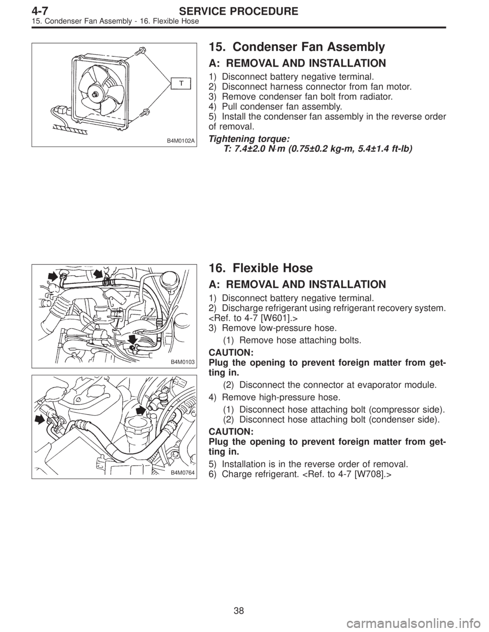
B4M0102A
15. Condenser Fan Assembly
A: REMOVAL AND INSTALLATION
1) Disconnect battery negative terminal.
2) Disconnect harness connector from fan motor.
3) Remove condenser fan bolt from radiator.
4) Pull condenser fan assembly.
5) Install the condenser fan assembly in the reverse order
of removal.
Tightening torque:
T: 7.4±2.0 N⋅m (0.75±0.2 kg-m, 5.4±1.4 ft-lb)
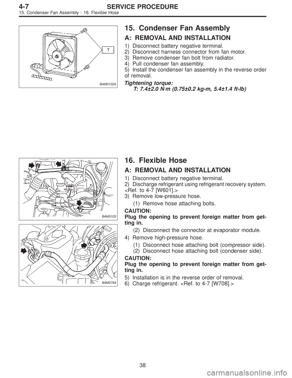
B4M0103
B4M0764
16. Flexible Hose
A: REMOVAL AND INSTALLATION
1) Disconnect battery negative terminal.
2) Discharge refrigerant using refrigerant recovery system.
3) Remove low-pressure hose.
(1) Remove hose attaching bolts.
CAUTION:
Plug the opening to prevent foreign matter from get-
ting in.
(2) Disconnect the connector at evaporator module.
4) Remove high-pressure hose.
(1) Disconnect hose attaching bolt (compressor side).
(2) Disconnect hose attaching bolt (condenser side).
CAUTION:
Plug the opening to prevent foreign matter from get-
ting in.
5) Installation is in the reverse order of removal.
6) Charge refrigerant.
38
4-7SERVICE PROCEDURE
15. Condenser Fan Assembly - 16. Flexible Hose
Page 1495 of 3342

B4M0102A
15. Condenser Fan Assembly
A: REMOVAL AND INSTALLATION
1) Disconnect battery negative terminal.
2) Disconnect harness connector from fan motor.
3) Remove condenser fan bolt from radiator.
4) Pull condenser fan assembly.
5) Install the condenser fan assembly in the reverse order
of removal.
Tightening torque:
T: 7.4±2.0 N⋅m (0.75±0.2 kg-m, 5.4±1.4 ft-lb)
B4M0103
B4M0764
16. Flexible Hose
A: REMOVAL AND INSTALLATION
1) Disconnect battery negative terminal.
2) Discharge refrigerant using refrigerant recovery system.
3) Remove low-pressure hose.
(1) Remove hose attaching bolts.
CAUTION:
Plug the opening to prevent foreign matter from get-
ting in.
(2) Disconnect the connector at evaporator module.
4) Remove high-pressure hose.
(1) Disconnect hose attaching bolt (compressor side).
(2) Disconnect hose attaching bolt (condenser side).
CAUTION:
Plug the opening to prevent foreign matter from get-
ting in.
5) Installation is in the reverse order of removal.
6) Charge refrigerant.
38
4-7SERVICE PROCEDURE
15. Condenser Fan Assembly - 16. Flexible Hose
Page 1496 of 3342
G4M0649
17. Relay and Fuse
A: LOCATION
Relays used with A/C system are located as shown in fig-
ure.
1) A/C relay
2) Main fan (radiator fan) relay
3) Sub fan (condenser fan) relay
4) Sub fan (condenser fan) water temperature relay
5) Fuses (10 A and 20 A)
G4M0651
B: INSPECTION
1) Check conduction with a circuit tester (ohm range)
according to the following table in figure.
B4M0105A
2) Replace relays which do not meet specifications.
39
4-7SERVICE PROCEDURE
17. Relay and Fuse
Page 1497 of 3342
G4M0654
18. Pressure Switch (Dual Switch)
Pressure switch is attached to receiver dryer.
A: INSPECTION
1) Remove cap from high-pressure line service valve, and
connect gauge manifold to service valve.
2) Disconnect pressure switch harness connector, and
check pressure switch for proper ON-OFF operation. Use
a circuit tester.
Terminal OperationHigh-pressure side line pressure
kPa (kg/cm2, psi)
High and low pressure
switch�
1—�2
Turns OFF.Increasing to
2,648±196 (27±2, 384±28)
Decreasing to
177±20 (1.8±0.2, 26±3)
Turns ON.Increasing to
186±29 (1.9±0.3, 27±4)
Decreasing to
1,471
+196
�98(15+2
�1, 213+28
�14)
40
4-7SERVICE PROCEDURE
18. Pressure Switch (Dual Switch)
Page 1509 of 3342
1. Supplemental Restraint System
“Airbag”
Airbag system wiring harness is routed on and along body
panels.
CAUTION:
�All Airbag system wiring harness and connectors
are colored yellow. Do not use electrical test equip-
ment on these circuits.
�Be careful not to damage Airbag system wiring har-
ness when repairing the body panel.
2. Body Datum Points
Various master repair locations are established as datum
points used during body repairs. In addition, guide holes,
locators and indents are provided to facilitate panel
replacement and achieve alignment accuracy.
NOTE:
Left and right datum points are all symmetrical to each
other.
2
5-1SERVICE DATA
1. Supplemental Restraint System“Airbag”- 2. Body Datum Points
Page 1510 of 3342
1. Supplemental Restraint System
“Airbag”
Airbag system wiring harness is routed on and along body
panels.
CAUTION:
�All Airbag system wiring harness and connectors
are colored yellow. Do not use electrical test equip-
ment on these circuits.
�Be careful not to damage Airbag system wiring har-
ness when repairing the body panel.
2. Body Datum Points
Various master repair locations are established as datum
points used during body repairs. In addition, guide holes,
locators and indents are provided to facilitate panel
replacement and achieve alignment accuracy.
NOTE:
Left and right datum points are all symmetrical to each
other.
2
5-1SERVICE DATA
1. Supplemental Restraint System“Airbag”- 2. Body Datum Points
Page 1511 of 3342

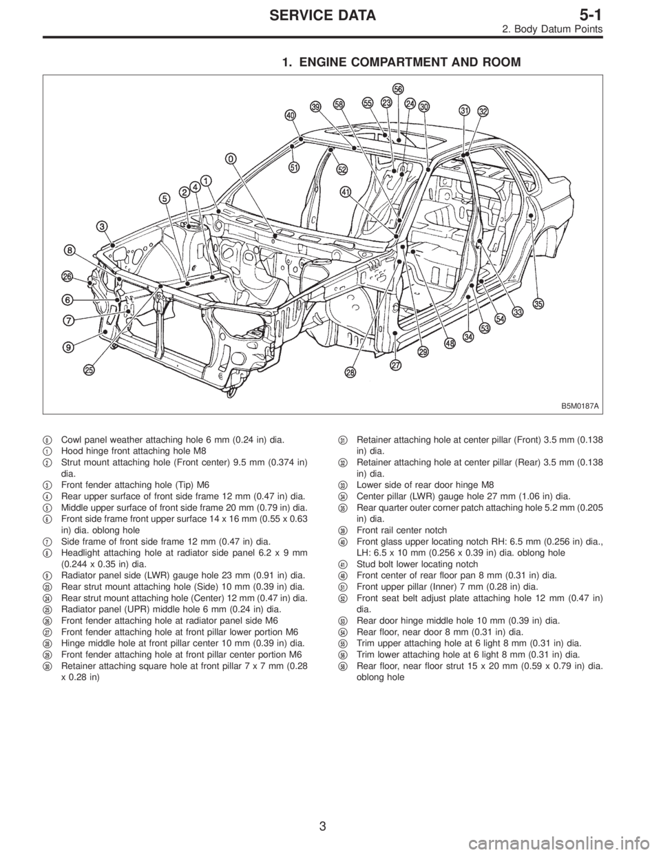
1. ENGINE COMPARTMENT AND ROOM
B5M0187A
�0Cowl panel weather attaching hole 6 mm (0.24 in) dia.
�
1Hood hinge front attaching hole M8
�
2Strut mount attaching hole (Front center) 9.5 mm (0.374 in)
dia.
�
3Front fender attaching hole (Tip) M6
�
4Rear upper surface of front side frame 12 mm (0.47 in) dia.
�
5Middle upper surface of front side frame 20 mm (0.79 in) dia.
�
6Front side frame front upper surface 14 x 16 mm (0.55 x 0.63
in) dia. oblong hole
�
7Side frame of front side frame 12 mm (0.47 in) dia.
�
8Headlight attaching hole at radiator side panel 6.2x9mm
(0.244 x 0.35 in) dia.
�
9Radiator panel side (LWR) gauge hole 23 mm (0.91 in) dia.
�
23Rear strut mount attaching hole (Side) 10 mm (0.39 in) dia.
�
24Rear strut mount attaching hole (Center) 12 mm (0.47 in) dia.
�
25Radiator panel (UPR) middle hole 6 mm (0.24 in) dia.
�
26Front fender attaching hole at radiator panel side M6
�
27Front fender attaching hole at front pillar lower portion M6
�
28Hinge middle hole at front pillar center 10 mm (0.39 in) dia.
�
29Front fender attaching hole at front pillar center portion M6
�
30Retainer attaching square hole at front pillar7x7mm(0.28
x 0.28 in)�
31Retainer attaching hole at center pillar (Front) 3.5 mm (0.138
in) dia.
�
32Retainer attaching hole at center pillar (Rear) 3.5 mm (0.138
in) dia.
�
33Lower side of rear door hinge M8
�
34Center pillar (LWR) gauge hole 27 mm (1.06 in) dia.
�
35Rear quarter outer corner patch attaching hole 5.2 mm (0.205
in) dia.
�
39Front rail center notch
�
40Front glass upper locating notch RH: 6.5 mm (0.256 in) dia.,
LH: 6.5 x 10 mm (0.256 x 0.39 in) dia. oblong hole
�
41Stud bolt lower locating notch
�
48Front center of rear floor pan 8 mm (0.31 in) dia.
�
51Front upper pillar (Inner) 7 mm (0.28 in) dia.
�
52Front seat belt adjust plate attaching hole 12 mm (0.47 in)
dia.
�
53Rear door hinge middle hole 10 mm (0.39 in) dia.
�
54Rear floor, near door 8 mm (0.31 in) dia.
�
55Trim upper attaching hole at 6 light 8 mm (0.31 in) dia.
�
56Trim lower attaching hole at 6 light 8 mm (0.31 in) dia.
�
58Rear floor, near floor strut 15 x 20 mm (0.59 x 0.79 in) dia.
oblong hole
3
5-1SERVICE DATA
2. Body Datum Points
Page 1512 of 3342
2. LUGGAGE COMPARTMENT AND ROOM (SEDAN)
B5M0188A
�366 light upper retainer attaching square hole7x7mm(0.28 x 0.28 in)
�
42Rear rail center notch
�
43Rear glass upper locating hole RH: 6.5 mm (0.256 in) dia., LH: 6.5 x 10 mm (0.256 x 0.39 in) dia. oblong hole
�
44Rear glass molding attaching square hole8x8mm(0.31 x 0.31 in)
�
45Rear panel drain locater concave part
�
46Front panel gauge hole 10 mm (0.39 in) dia.
�
47Tunnel center M8
�
59Rear bumper attaching hole 45 mm (1.77 in) dia.
�
65Rear wiper attaching hole M6
�
66Trim attaching hole at rear skirt (UPR) 7 mm (0.28 in) dia.
�
67Rear bumper side attaching hole 6 mm (0.24 in) dia.
�
68Rear combination light mounting hole 8 mm (0.31 in) dia.
�
69Rear bumper beam attaching hole RH: 8 mm (0.31 in) dia., LH:8x12mm(0.31 x 0.47 in) dia. oblong hole
4
5-1SERVICE DATA
2. Body Datum Points