Page 1478 of 3342

G4M0615
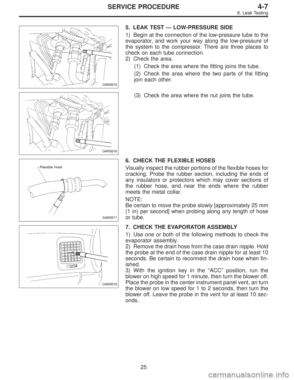
5. LEAK TEST—LOW-PRESSURE SIDE
1) Begin at the connection of the low-pressure tube to the
evaporator, and work your way along the low-pressure of
the system to the compressor. There are three places to
check on each tube connection.
2) Check the area.
(1) Check the area where the fitting joins the tube.
(2) Check the area where the two parts of the fitting
join each other.
G4M0616
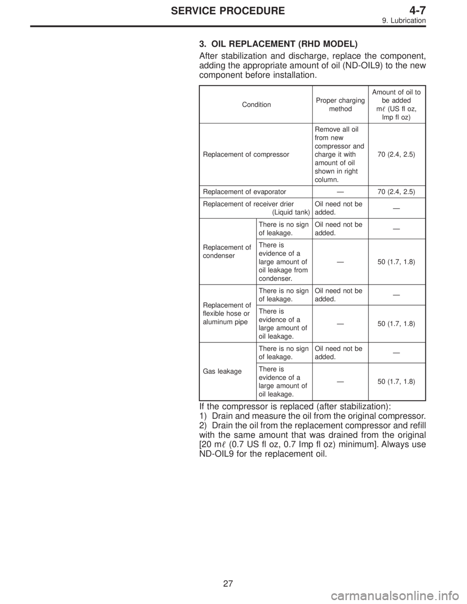
(3) Check the area where the nut joins the tube.
G4M0617
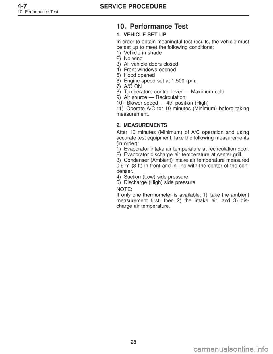
6. CHECK THE FLEXIBLE HOSES
Visually inspect the rubber portions of the flexible hoses for
cracking. Probe the rubber section, including the ends of
any insulators or protectors which may cover sections of
the rubber hose, and near the ends where the rubber
meets the metal collar.
NOTE:
Be certain to move the probe slowly [approximately 25 mm
(1 in) per second] when probing along any length of hose
or tube.
G4M0618
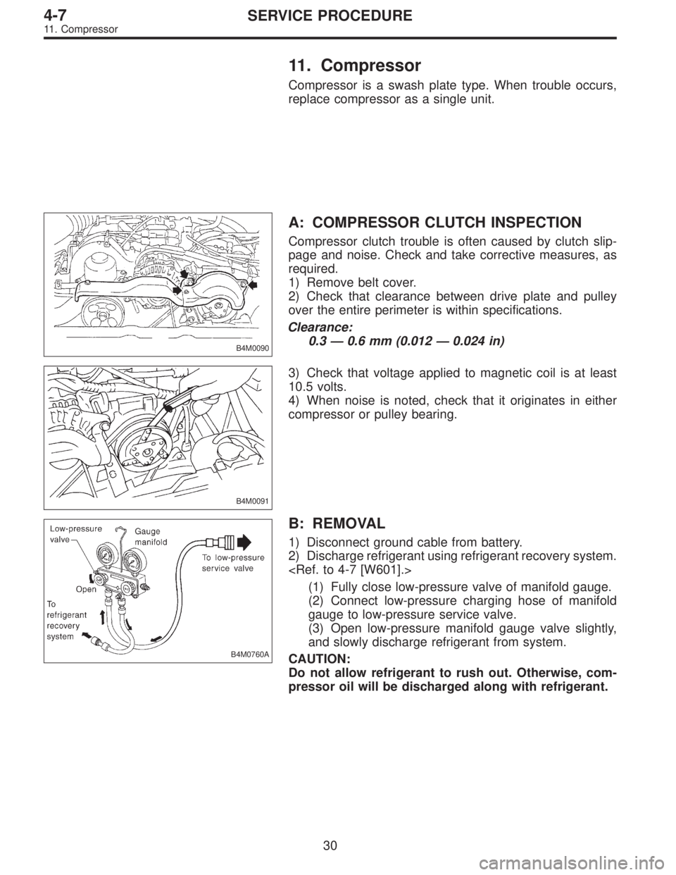
7. CHECK THE EVAPORATOR ASSEMBLY
1) Use one or both of the following methods to check the
evaporator assembly.
2) Remove the drain hose from the case drain nipple. Hold
the probe at the end of the case drain nipple for at least 10
seconds. Be certain to reconnect the drain hose when fin-
ished.
3) With the ignition key in the“ACC”position, run the
blower on high speed for 1 minute, then turn the blower off.
Place the probe in the center instrument panel vent, an turn
the blower on low speed for 1 to 2 seconds, then turn the
blower off. Leave the probe in the vent for at least 10 sec-
onds.
25
4-7SERVICE PROCEDURE
8. Leak Testing
Page 1479 of 3342
G4M0619
8. CHECK THE SERVICE PORT CAPS
Visually inspect the inside of the service port caps. Make
sure the rubber seal is in place on the inside of the caps.
Disconnect the gauges from the vehicle and install the
service port caps.
9. Lubrication
1. SYSTEM OIL STABILIZATION
Prior to opening the refrigerant system for repairs (except
compressor seizure) the system must be stabilized for cor-
rect oil replenishment.
Follow these procedures:
1) Engine speed set to 1,500 rpm
2) A/C“ON”
3) Air source to recirculate
4) Blower in 4th or high speed position
�Make sure the air entering the evaporator is above
26.7°C (80°F).
�The discharge (high) side pressure must be above
588 kPa (6 kg/cm
2, 85 psi).
5) Operate the A/C for 10 minutes.
2. SYSTEM DISCHARGE
Slowly, discharge the system starting with the high- pres-
sure side until the pressure drops below 345 kPa (3.52
kg/cm
2, 50 psi), then open the low-pressure side.
26
4-7SERVICE PROCEDURE
8. Leak Testing - 9. Lubrication
Page 1480 of 3342
G4M0619
8. CHECK THE SERVICE PORT CAPS
Visually inspect the inside of the service port caps. Make
sure the rubber seal is in place on the inside of the caps.
Disconnect the gauges from the vehicle and install the
service port caps.
9. Lubrication
1. SYSTEM OIL STABILIZATION
Prior to opening the refrigerant system for repairs (except
compressor seizure) the system must be stabilized for cor-
rect oil replenishment.
Follow these procedures:
1) Engine speed set to 1,500 rpm
2) A/C“ON”
3) Air source to recirculate
4) Blower in 4th or high speed position
�Make sure the air entering the evaporator is above
26.7°C (80°F).
�The discharge (high) side pressure must be above
588 kPa (6 kg/cm
2, 85 psi).
5) Operate the A/C for 10 minutes.
2. SYSTEM DISCHARGE
Slowly, discharge the system starting with the high- pres-
sure side until the pressure drops below 345 kPa (3.52
kg/cm
2, 50 psi), then open the low-pressure side.
26
4-7SERVICE PROCEDURE
8. Leak Testing - 9. Lubrication
Page 1481 of 3342

3. OIL REPLACEMENT (RHD MODEL)
After stabilization and discharge, replace the component,
adding the appropriate amount of oil (ND-OIL9) to the new
component before installation.
ConditionProper charging
methodAmount of oil to
be added
m�(US fl oz,
lmp fl oz)
Replacement of compressorRemove all oil
from new
compressor and
charge it with
amount of oil
shown in right
column.70 (2.4, 2.5)
Replacement of evaporator—70 (2.4, 2.5)
Replacement of receiver drier
(Liquid tank)Oil need not be
added.—
Replacement of
condenserThere is no sign
of leakage.Oil need not be
added.—
There is
evidence of a
large amount of
oil leakage from
condenser.—50 (1.7, 1.8)
Replacement of
flexible hose or
aluminum pipeThere is no sign
of leakage.Oil need not be
added.—
There is
evidence of a
large amount of
oil leakage.—50 (1.7, 1.8)
Gas leakageThere is no sign
of leakage.Oil need not be
added.—
There is
evidence of a
large amount of
oil leakage.—50 (1.7, 1.8)
If the compressor is replaced (after stabilization):
1) Drain and measure the oil from the original compressor.
2) Drain the oil from the replacement compressor and refill
with the same amount that was drained from the original
[20 m�(0.7 US fl oz, 0.7 Imp fl oz) minimum]. Always use
ND-OIL9 for the replacement oil.
27
4-7SERVICE PROCEDURE
9. Lubrication
Page 1482 of 3342

10. Performance Test
1. VEHICLE SET UP
In order to obtain meaningful test results, the vehicle must
be set up to meet the following conditions:
1) Vehicle in shade
2) No wind
3) All vehicle doors closed
4) Front windows opened
5) Hood opened
6) Engine speed set at 1,500 rpm.
7) A/C ON
8) Temperature control lever—Maximum cold
9) Air source—Recirculation
10) Blower speed—4th position (High)
11) Operate A/C for 10 minutes (Minimum) before taking
measurement.
2. MEASUREMENTS
After 10 minutes (Minimum) of A/C operation and using
accurate test equipment, take the following measurements
(in order):
1) Evaporator intake air temperature at recirculation door.
2) Evaporator discharge air temperature at center grill.
3) Condenser (Ambient) intake air temperature measured
0.9 m (3 ft) in front and in line with the center of the con-
denser.
4) Suction (Low) side pressure
5) Discharge (High) side pressure
NOTE:
If only one thermometer is available; 1) take the ambient
measurement first; then 2) the intake air; and 3) dis-
charge air temperature.
28
4-7SERVICE PROCEDURE
10. Performance Test
Page 1483 of 3342
3. MEASUREMENT STANDARD BY VERSES
Compare temperature and pressure measurements with
the established standards shown in the following charts.
B4M0371A
29
4-7SERVICE PROCEDURE
10. Performance Test
Page 1484 of 3342

11. Compressor
Compressor is a swash plate type. When trouble occurs,
replace compressor as a single unit.
B4M0090
A: COMPRESSOR CLUTCH INSPECTION
Compressor clutch trouble is often caused by clutch slip-
page and noise. Check and take corrective measures, as
required.
1) Remove belt cover.
2) Check that clearance between drive plate and pulley
over the entire perimeter is within specifications.
Clearance:
0.3 — 0.6 mm (0.012 — 0.024 in)
B4M0091
3) Check that voltage applied to magnetic coil is at least
10.5 volts.
4) When noise is noted, check that it originates in either
compressor or pulley bearing.
B4M0760A
B: REMOVAL
1) Disconnect ground cable from battery.
2) Discharge refrigerant using refrigerant recovery system.
(1) Fully close low-pressure valve of manifold gauge.
(2) Connect low-pressure charging hose of manifold
gauge to low-pressure service valve.
(3) Open low-pressure manifold gauge valve slightly,
and slowly discharge refrigerant from system.
CAUTION:
Do not allow refrigerant to rush out. Otherwise, com-
pressor oil will be discharged along with refrigerant.
30
4-7SERVICE PROCEDURE
11. Compressor
Page 1485 of 3342
B4M0761A
3) Remove low-pressure hose�1(Flexible hose Ps) and
high-pressure hose�
2(Flexible hose Pd).
CAUTION:
�Be careful not to lose O-ring of low-pressure hose.
�Plug the opening to prevent foreign matter from
entering.
G4M0624
4) Remove compressor belt cover and alternator belt
cover.
Remove bolts which secure belt covers.
G4M0625
5) Remove alternator V-belt.
Loosen lock bolt on alternator bracket. Turn adjusting bolt
and remove V-belt.
G4M0626
6) Remove compressor V-belt.
Loosen lock nut on idler pulley. Turn adjusting bolt and
remove V-belt.
G4M0627
7) Disconnect alternator harness.
31
4-7SERVICE PROCEDURE
11. Compressor