Page 1434 of 3342
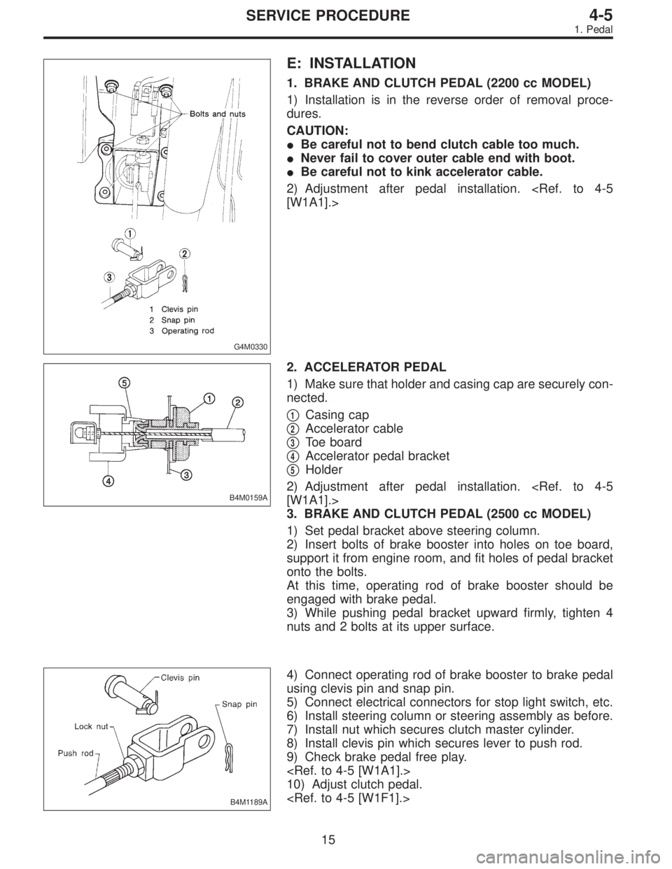
G4M0330
E: INSTALLATION
1. BRAKE AND CLUTCH PEDAL (2200 cc MODEL)
1) Installation is in the reverse order of removal proce-
dures.
CAUTION:
�Be careful not to bend clutch cable too much.
�Never fail to cover outer cable end with boot.
�Be careful not to kink accelerator cable.
2) Adjustment after pedal installation.
[W1A1].>
B4M0159A
2. ACCELERATOR PEDAL
1) Make sure that holder and casing cap are securely con-
nected.
�
1Casing cap
�
2Accelerator cable
�
3Toe board
�
4Accelerator pedal bracket
�
5Holder
2) Adjustment after pedal installation.
[W1A1].>
3. BRAKE AND CLUTCH PEDAL (2500 cc MODEL)
1) Set pedal bracket above steering column.
2) Insert bolts of brake booster into holes on toe board,
support it from engine room, and fit holes of pedal bracket
onto the bolts.
At this time, operating rod of brake booster should be
engaged with brake pedal.
3) While pushing pedal bracket upward firmly, tighten 4
nuts and 2 bolts at its upper surface.
B4M1189A
4) Connect operating rod of brake booster to brake pedal
using clevis pin and snap pin.
5) Connect electrical connectors for stop light switch, etc.
6) Install steering column or steering assembly as before.
7) Install nut which secures clutch master cylinder.
8) Install clevis pin which secures lever to push rod.
9) Check brake pedal free play.
10) Adjust clutch pedal.
15
4-5SERVICE PROCEDURE
1. Pedal
Page 1435 of 3342
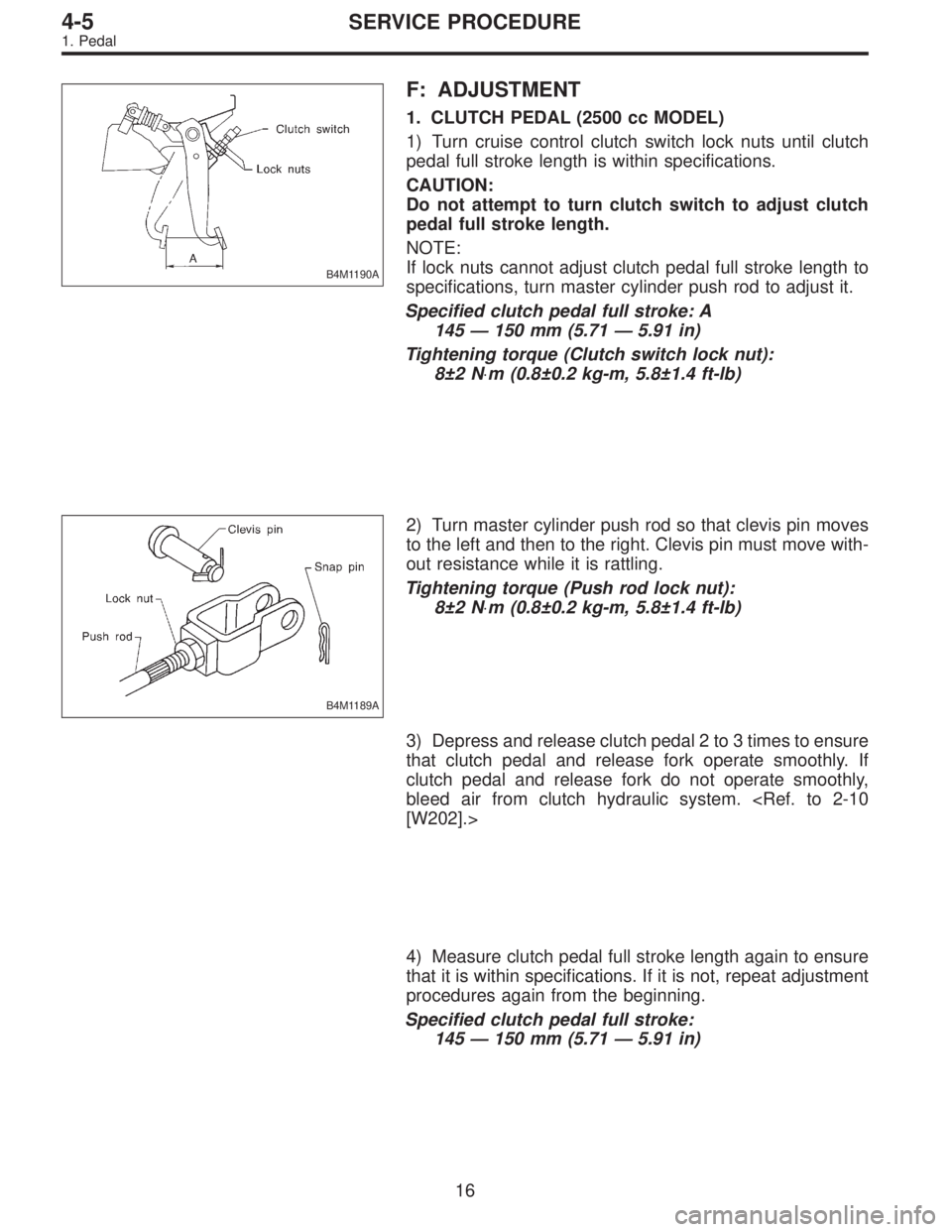
B4M1190A
F: ADJUSTMENT
1. CLUTCH PEDAL (2500 cc MODEL)
1) Turn cruise control clutch switch lock nuts until clutch
pedal full stroke length is within specifications.
CAUTION:
Do not attempt to turn clutch switch to adjust clutch
pedal full stroke length.
NOTE:
If lock nuts cannot adjust clutch pedal full stroke length to
specifications, turn master cylinder push rod to adjust it.
Specified clutch pedal full stroke: A
145—150 mm (5.71—5.91 in)
Tightening torque (Clutch switch lock nut):
8±2 N⋅m (0.8±0.2 kg-m, 5.8±1.4 ft-lb)
B4M1189A
2) Turn master cylinder push rod so that clevis pin moves
to the left and then to the right. Clevis pin must move with-
out resistance while it is rattling.
Tightening torque (Push rod lock nut):
8±2 N⋅m (0.8±0.2 kg-m, 5.8±1.4 ft-lb)
3) Depress and release clutch pedal 2 to 3 times to ensure
that clutch pedal and release fork operate smoothly. If
clutch pedal and release fork do not operate smoothly,
bleed air from clutch hydraulic system.
[W202].>
4) Measure clutch pedal full stroke length again to ensure
that it is within specifications. If it is not, repeat adjustment
procedures again from the beginning.
Specified clutch pedal full stroke:
145—150 mm (5.71—5.91 in)
16
4-5SERVICE PROCEDURE
1. Pedal
Page 1436 of 3342
5) Move clevis pin to the left and then to the right. It should
move without resistance while it is rattling. If resistance is
felt, repeat adjustment procedures again from the begin-
ning.
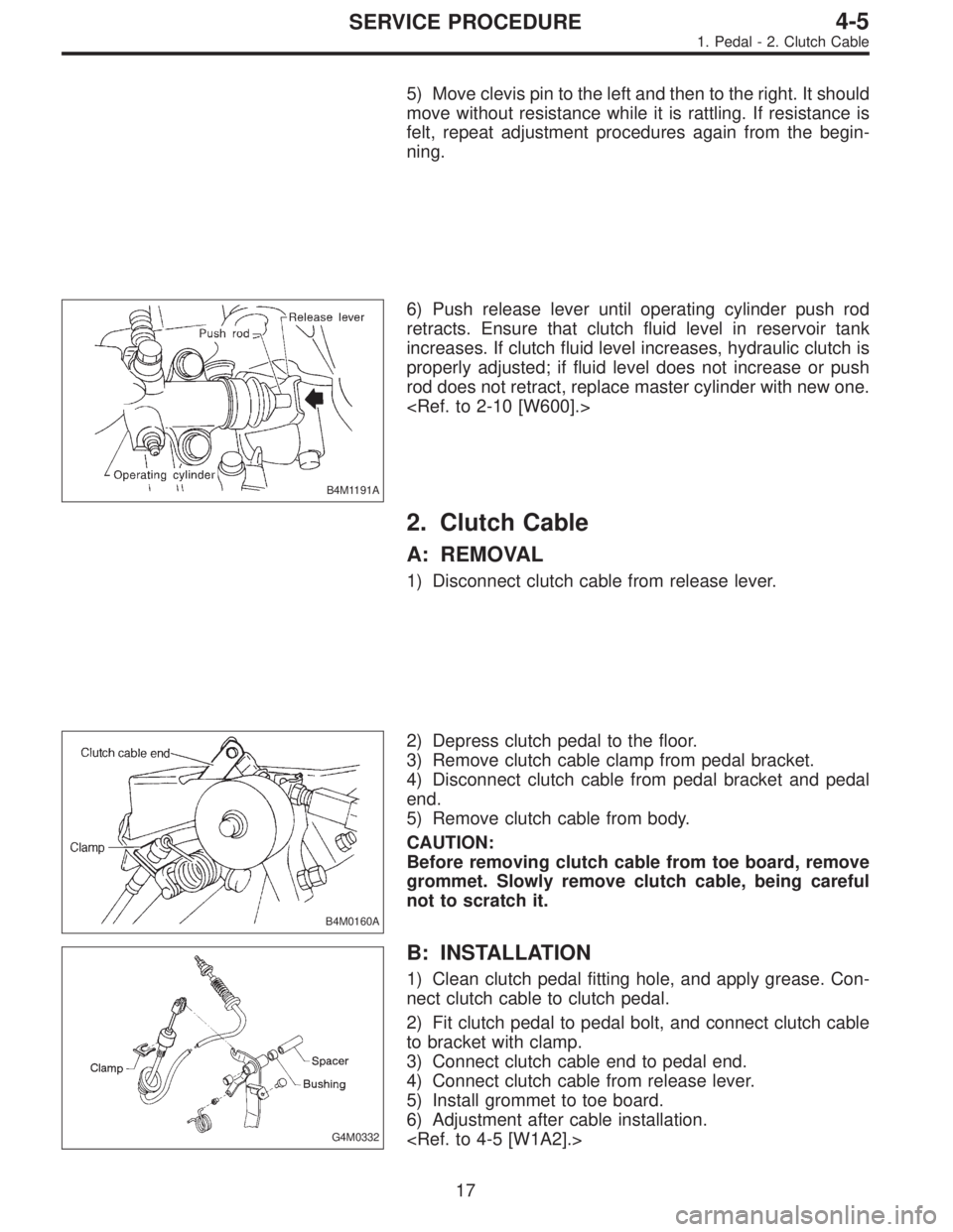
B4M1191A
6) Push release lever until operating cylinder push rod
retracts. Ensure that clutch fluid level in reservoir tank
increases. If clutch fluid level increases, hydraulic clutch is
properly adjusted; if fluid level does not increase or push
rod does not retract, replace master cylinder with new one.
2. Clutch Cable
A: REMOVAL
1) Disconnect clutch cable from release lever.
B4M0160A
2) Depress clutch pedal to the floor.
3) Remove clutch cable clamp from pedal bracket.
4) Disconnect clutch cable from pedal bracket and pedal
end.
5) Remove clutch cable from body.
CAUTION:
Before removing clutch cable from toe board, remove
grommet. Slowly remove clutch cable, being careful
not to scratch it.
G4M0332
B: INSTALLATION
1) Clean clutch pedal fitting hole, and apply grease. Con-
nect clutch cable to clutch pedal.
2) Fit clutch pedal to pedal bolt, and connect clutch cable
to bracket with clamp.
3) Connect clutch cable end to pedal end.
4) Connect clutch cable from release lever.
5) Install grommet to toe board.
6) Adjustment after cable installation.
17
4-5SERVICE PROCEDURE
1. Pedal - 2. Clutch Cable
Page 1437 of 3342
5) Move clevis pin to the left and then to the right. It should
move without resistance while it is rattling. If resistance is
felt, repeat adjustment procedures again from the begin-
ning.
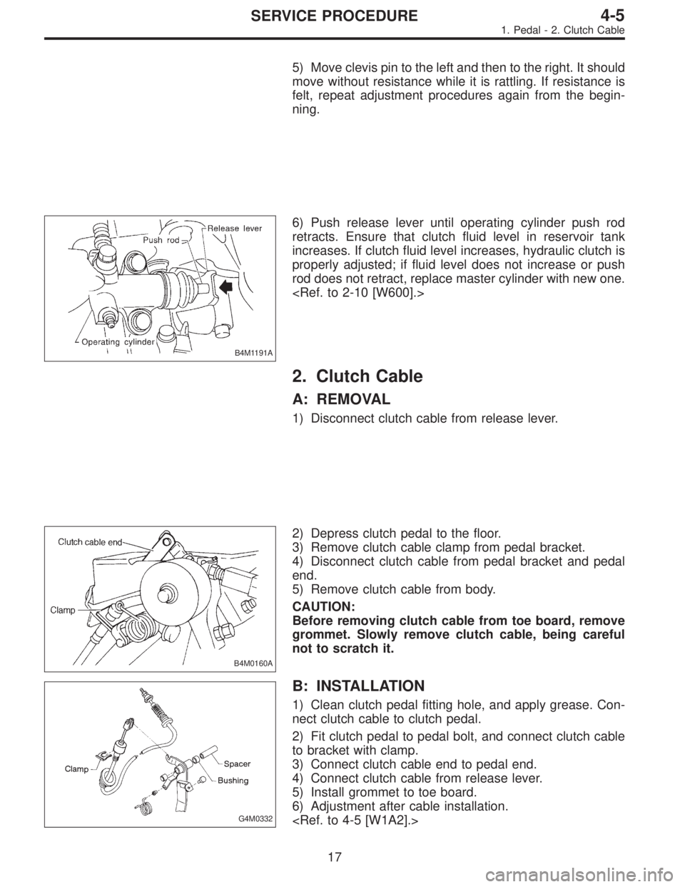
B4M1191A
6) Push release lever until operating cylinder push rod
retracts. Ensure that clutch fluid level in reservoir tank
increases. If clutch fluid level increases, hydraulic clutch is
properly adjusted; if fluid level does not increase or push
rod does not retract, replace master cylinder with new one.
2. Clutch Cable
A: REMOVAL
1) Disconnect clutch cable from release lever.
B4M0160A
2) Depress clutch pedal to the floor.
3) Remove clutch cable clamp from pedal bracket.
4) Disconnect clutch cable from pedal bracket and pedal
end.
5) Remove clutch cable from body.
CAUTION:
Before removing clutch cable from toe board, remove
grommet. Slowly remove clutch cable, being careful
not to scratch it.
G4M0332
B: INSTALLATION
1) Clean clutch pedal fitting hole, and apply grease. Con-
nect clutch cable to clutch pedal.
2) Fit clutch pedal to pedal bolt, and connect clutch cable
to bracket with clamp.
3) Connect clutch cable end to pedal end.
4) Connect clutch cable from release lever.
5) Install grommet to toe board.
6) Adjustment after cable installation.
17
4-5SERVICE PROCEDURE
1. Pedal - 2. Clutch Cable
Page 1438 of 3342
3. Accelerator Cable
1. LHD MODEL
B4M0768A
2. RHD MODEL
B4M1157A
18
4-5SERVICE PROCEDURE
3. Accelerator Cable
Page 1439 of 3342
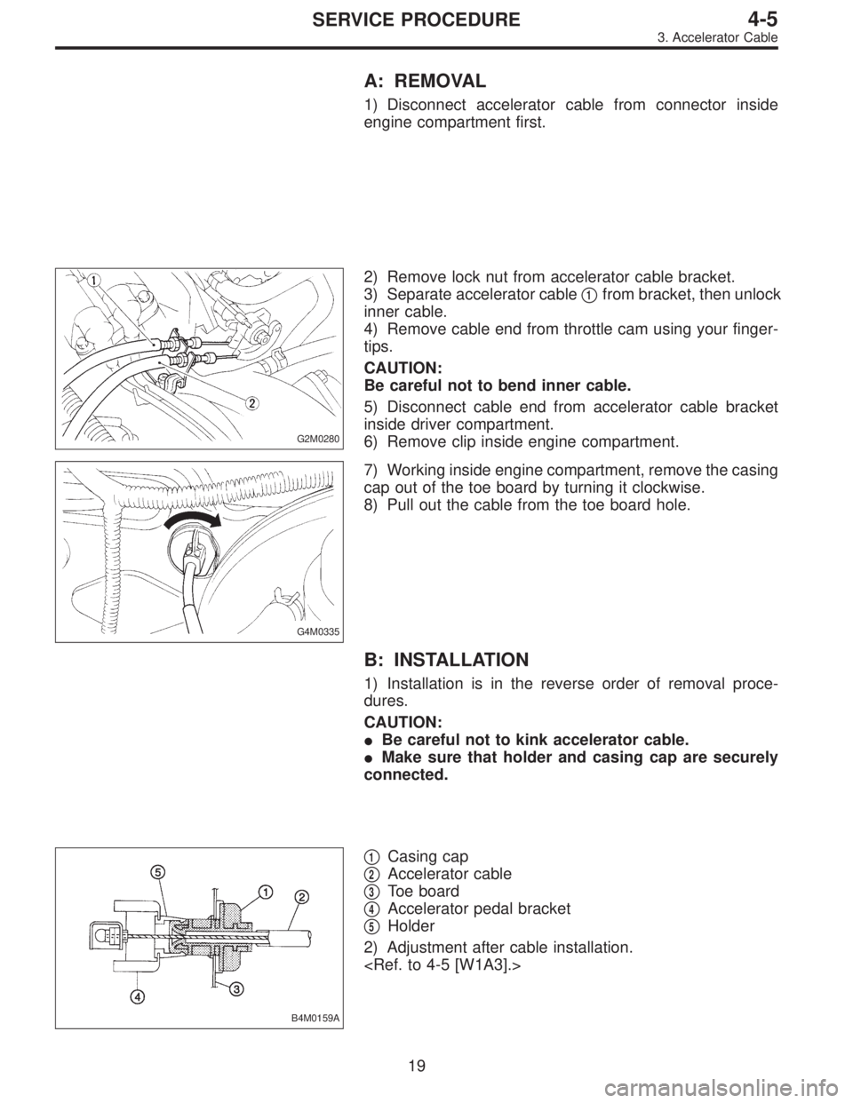
A: REMOVAL
1) Disconnect accelerator cable from connector inside
engine compartment first.
G2M0280
2) Remove lock nut from accelerator cable bracket.
3) Separate accelerator cable�
1from bracket, then unlock
inner cable.
4) Remove cable end from throttle cam using your finger-
tips.
CAUTION:
Be careful not to bend inner cable.
5) Disconnect cable end from accelerator cable bracket
inside driver compartment.
6) Remove clip inside engine compartment.
G4M0335
7) Working inside engine compartment, remove the casing
cap out of the toe board by turning it clockwise.
8) Pull out the cable from the toe board hole.
B: INSTALLATION
1) Installation is in the reverse order of removal proce-
dures.
CAUTION:
�Be careful not to kink accelerator cable.
�Make sure that holder and casing cap are securely
connected.
B4M0159A
�1Casing cap
�
2Accelerator cable
�
3Toe board
�
4Accelerator pedal bracket
�
5Holder
2) Adjustment after cable installation.
19
4-5SERVICE PROCEDURE
3. Accelerator Cable
Page 1441 of 3342
1. Heater System
A: SPECIFICATIONS
Item Specifications Condition
Heating capacity4.652 kW (4,000 kcal/h, 15,872 BTU/h) or more ...
When 300 m
3(10,593 cu ft)/h�Mode
selector
switch: HEAT
�Te m p .
control lever: FULL HOT
�Temperature
difference
between hot
water and
inlet air:65°C (149°F)
�Hot water
flow rate: 360�(95.1
US gal, 79.2
Imp gal)/h
Air flow rate 300 m
3(10,593 cu ft)/hHeat mode (FRESH), FULL
HOT at 12.5 V
Max air flow rate 510 m
3(18,008 cu ft)/h�Temperature
control lever: FULL COLD
�Blower fan
speed: 4th position
�RECIRC
switch
position: RECIRC
Heater core size
(height x length x width x
thickness)193.5 x 152.0 x 25.0 x 0.9 mm
(7.62 x 5.98 x 0.984 x 0.035 in)—
Blower
motorType Magnet motor 230 W or less at 12 V
Fan type and size
(diameter x width)Sirocco fan type
150 x 75 mm (5.91 x 2.95 in)—
2
4-6SPECIFICATIONS AND SERVICE DATA
1. Heater System
Page 1446 of 3342
1. Supplemental Restraint System
“Airbag”
Airbag system wiring harness is routed near the instrument
panel, heater unit, blower motor and control unit.
CAUTION:
�All Airbag system wiring harness and connectors
are colored yellow. Do not use electrical test equip-
ment on these circuit.
�Be careful not to damage Airbag system wiring har-
ness when servicing the instrument panel, heater unit,
blower motor and control unit.
2. Heater Unit
A: REMOVAL AND INSTALLATION
1) Disconnect GND cable from battery.
2) Remove heater hoses (inlet, outlet) in engine compart-
ment.
NOTE:
Drain as much coolant from heater unit as possible, and
plug disconnected hose with cloth.
3) Remove instrument panel.
4) Remove steering support beam.
5) Remove evaporator. (With A/C model)
G4M0554
6) Remove heater unit.
7
4-6SERVICE PROCEDURE
1. Supplemental Restraint System“Airbag”- 2. Heater Unit