Page 1403 of 3342
B4M0628
G: INSTALLATION
1) Install hydraulic unit and bracket.
Tightening torque:
32±7 N⋅m (3.3±0.7 kg-m, 23.9±5.1 ft-lb)
2) Connect brake pipes to their correct hydraulic unit con-
nections.
3) Connect connector to hydraulic unit.
4) Install canister.
5) Install air cleaner case.
6) Install air intake duct.
7) Connect ground cable to battery.
CAUTION:
Cover relay securely with rubber boot.
21. ABS/TCS Control Module
A: REMOVAL
1) Disconnect ground cable from battery.
2) Remove floor mat located under lower right side of front
seat.
B4M0643A
3) Remove screw which secure ABS/TCS control module
from the body.
4) Disconnect connector from ABS/TCS control module.
B: INSPECTION
Check that connector is connected correctly and that con-
nector terminal sliding resistance is correct.
11 9
4-4SERVICE PROCEDURE
20. Hydraulic Unit for ABS/TCS System - 21. ABS/TCS Control Module
Page 1404 of 3342
B4M0628
G: INSTALLATION
1) Install hydraulic unit and bracket.
Tightening torque:
32±7 N⋅m (3.3±0.7 kg-m, 23.9±5.1 ft-lb)
2) Connect brake pipes to their correct hydraulic unit con-
nections.
3) Connect connector to hydraulic unit.
4) Install canister.
5) Install air cleaner case.
6) Install air intake duct.
7) Connect ground cable to battery.
CAUTION:
Cover relay securely with rubber boot.
21. ABS/TCS Control Module
A: REMOVAL
1) Disconnect ground cable from battery.
2) Remove floor mat located under lower right side of front
seat.
B4M0643A
3) Remove screw which secure ABS/TCS control module
from the body.
4) Disconnect connector from ABS/TCS control module.
B: INSPECTION
Check that connector is connected correctly and that con-
nector terminal sliding resistance is correct.
11 9
4-4SERVICE PROCEDURE
20. Hydraulic Unit for ABS/TCS System - 21. ABS/TCS Control Module
Page 1405 of 3342
C: INSTALLATION
1) Connect connector to ABS/TCS control module.
2) Install ABS/TCS control module on the body.
CAUTION:
�When installing seat rail, be careful no to have the
harness caught in the rail.
�Cover the connector completely with rubber boot.
120
4-4SERVICE PROCEDURE
21. ABS/TCS Control Module
Page 1406 of 3342
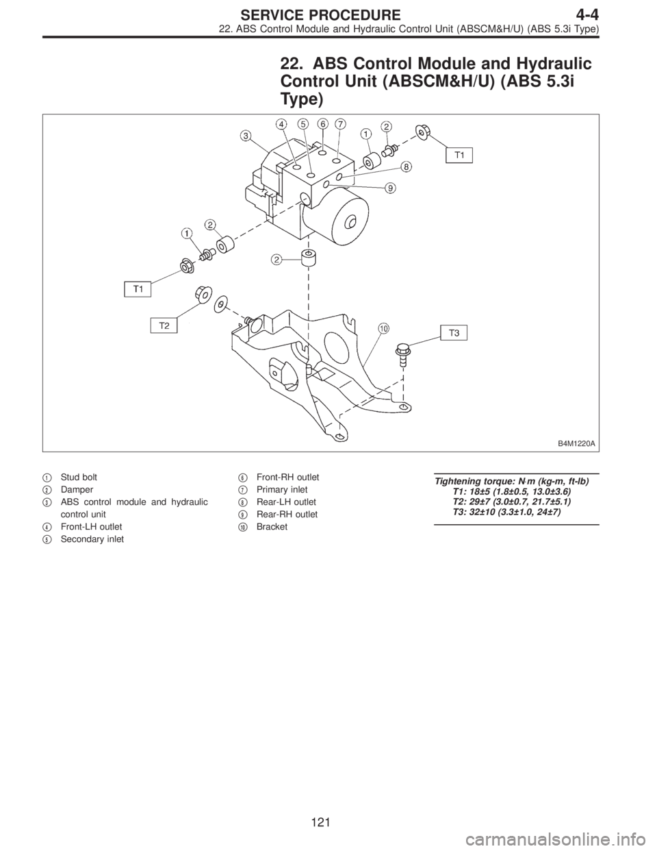
22. ABS Control Module and Hydraulic
Control Unit (ABSCM&H/U) (ABS 5.3i
Type)
B4M1220A
�1Stud bolt
�
2Damper
�
3ABS control module and hydraulic
control unit
�
4Front-LH outlet
�
5Secondary inlet�
6Front-RH outlet
�
7Primary inlet
�
8Rear-LH outlet
�
9Rear-RH outlet
�
10Bracket
Tightening torque: N⋅m (kg-m, ft-lb)
T1: 18±5 (1.8±0.5, 13.0±3.6)
T2: 29±7 (3.0±0.7, 21.7±5.1)
T3: 32±10 (3.3±1.0, 24±7)
121
4-4SERVICE PROCEDURE
22. ABS Control Module and Hydraulic Control Unit (ABSCM&H/U) (ABS 5.3i Type)
Page 1407 of 3342
 Disconnect ground cable from battery.
2) Remove air intake duct from engine compartment to
facilitate removal of ABSCM&H/U.
3) Use an air-gun to get rid of water around the
ABSCM&H/U.
CA")
A: REMOVAL
1) Disconnect ground cable from battery.
2) Remove air intake duct from engine compartment to
facilitate removal of ABSCM&H/U.
3) Use an air-gun to get rid of water around the
ABSCM&H/U.
CAUTION:
The contact will be insufficient if the terminal gets wet.
B4M1224A
4) Pull on the lock of the ABSCM&H/U connector to
remove it.
5) Disconnect connector from ABSCM&H/U.
CAUTION:
Be careful not to let water or other foreign matter con-
tact the ABSCM&H/U terminal.
6) Unlock cable clip.
7) Disconnect brake pipes from ABSCM&H/U.
CAUTION:
Wrap brake pipes with vinyl bag to avoid spilling brake
fluid on vehicle body.
B4M1222
8) Remove ABSCM&H/U from engine compartment.
CAUTION:
�ABSCM&H/U cannot be disassembled. Do not
attempt to loosen bolts and nuts.
�Do not drop or bump ABSCM&H/U.
�Do not turn the ABSCM&H/U upside down or place
it on its side.
�Be careful to prevent foreign particles from getting
into ABSCM&H/U.
�Apply a coat of rust-preventive wax (Nippeco LT or
GB) to bracket attaching bolt after tightening.
�Do not pull harness disconnecting harness connec-
tor.
122
4-4SERVICE PROCEDURE
22. ABS Control Module and Hydraulic Control Unit (ABSCM&H/U) (ABS 5.3i Type)
Page 1408 of 3342
B: INSPECTION
1) Check connected and fixed condition of connector.
B4M1248A
2) Check specifications of the mark with ABSCM&H/U.
Mark Model
C3 AWD AT
C4 AWD MT
C: CHECKING THE HYDRAULIC UNIT ABS
OPERATION
1. CHECKING THE HYDRAULIC UNIT ABS
OPERATION BY PRESSURE GAUGE
1) Lift-up vehicle and remove wheels.
2) Disconnect the air bleeder screws from the FL and FR
caliper bodies.
B4M0633A
3) Connect two pressure gauges to the FL and FR caliper
bodies.
CAUTION:
�Pressure gauges used exclusively for brake fluid
must be used.
�Do not employ pressure gauge previously used for
transmission since the piston seal is expanded which
may lead to malfunction of the brake.
NOTE:
Wrap sealing tape around the pressure gauge.
123
4-4SERVICE PROCEDURE
22. ABS Control Module and Hydraulic Control Unit (ABSCM&H/U) (ABS 5.3i Type)
Page 1409 of 3342
![SUBARU LEGACY 1997 Service Repair Manual 4) Bleed air from the pressure gauges.
5) Perform ABS sequence control.
<Ref. to 4-4 [W22D0].>
6) When the hydraulic unit begins to work, and first the FL
side performs decompression, holding, and com](/manual-img/17/57434/w960_57434-1408.png "SUBARU LEGACY 1997 Service Repair Manual 4) Bleed air from the pressure gauges.
5) Perform ABS sequence control.
<Ref. to 4-4 [W22D0].>
6) When the hydraulic unit begins to work, and first the FL
side performs decompression, holding, and com")
4) Bleed air from the pressure gauges.
5) Perform ABS sequence control.
6) When the hydraulic unit begins to work, and first the FL
side performs decompression, holding, and compression,
and then the FR side performs decompression, holding,
and compression.
7) Read values indicated on the pressure gauge and
check if the fluctuation of the values between decompres-
sion and compression meets the standard values. Also
check if any irregular brake pedal tightness is felt.
Initial value When decompressed When compressed
Front wheel 3,432 kPa (35 kg/cm
2, 498 psi)490 kPa (5 kg/cm2, 71 psi)
or less3,432 kPa (35 kg/cm2, 498 psi)
or more
Rear wheel 3,432 kPa (35 kg/cm
2, 498 psi)490 kPa (5 kg/cm2, 71 psi)
or less3,432 kPa (35 kg/cm2, 498 psi)
or more
8) Remove pressure gauges from FL and FR caliper bod-
ies.
9) Remove air bleeder screws from the RL and RR caliper
bodies.
10) Connect the air bleeder screws to the FL and FR cali-
per bodies.
11) Connect two pressure gauges to the RL and RR cali-
per bodies.
12) Bleed air from the pressure gauges and the FL and FR
caliper bodies.
13) Perform ABS sequence control.
14) When the hydraulic unit begins to work, at first the RR
side performs decompression, holding, and compression,
and then the RL side performs decompression, holding,
and compression.
15) Read values indicated on the pressure gauges and
check if they meet the standard value.
16) After checking, remove the pressure gauges from cali-
per bodies.
17) Connect the air bleeder screws to RL and RR caliper
bodies.
18) Bleed air from brake line.
124
4-4SERVICE PROCEDURE
22. ABS Control Module and Hydraulic Control Unit (ABSCM&H/U) (ABS 5.3i Type)
Page 1410 of 3342
 In the case of AWD AT vehicles, install a spare fuse with
the FWD connector in the engine compartment to simulate
FWD vehicles")
G4M0462
2. CHECKING THE HYDRAULIC UNIT ABS
OPERATION WITH BRAKE TESTER
1) In the case of AWD AT vehicles, install a spare fuse with
the FWD connector in the engine compartment to simulate
FWD vehicles.
2) Prepare for operating ABS sequence control.
4-4 [W22D1] or 4-4 [W22D2].>
G4M0464
3) Set the front wheels or rear wheels on the brake tester
and set the select lever’s position at“neutral”.
4) Operate the brake tester.
5) Perform ABS sequence control.
step 1 or 4-4 [W22D2] step 1.>
6) Hydraulic unit begins to work; and check the following
working sequence.
(1) The FL wheel performs decompression, holding,
and compression in sequence, and subsequently the
FR wheel repeats the cycle.
(2) The RR wheel performs decompression, holding,
and compression in sequence, and subsequently the
RL wheel repeats the cycle.
7) Read values indicated on the brake tester and check if
the fluctuation of values, when decompressed and
compressed, meet the standard values.
Unit: N (kg, lb)
Initial value When decompressed When compressed
Front wheel 981 (100, 221) 490 (50, 110) or less 981 (100, 221) or more
Rear wheel 981 (100, 221) 490 (50, 110) or less 981 (100, 221) or more
8) After checking, also check if any irregular brake pedal
tightness is felt.
125
4-4SERVICE PROCEDURE
22. ABS Control Module and Hydraulic Control Unit (ABSCM&H/U) (ABS 5.3i Type)
 Install hydraulic unit and bracket.
Tightening torque:
32±7 N⋅m (3.3±0.7 kg-m, 23.9±5.1 ft-lb)
2) Connect brake pipes to their correct hydraulic unit con-
nections. <Re")
 Install hydraulic unit and bracket.
Tightening torque:
32±7 N⋅m (3.3±0.7 kg-m, 23.9±5.1 ft-lb)
2) Connect brake pipes to their correct hydraulic unit con-
nections. <Re")
 Check connected and fixed condition of connector.
B4M1248A
2) Check specifications of the mark with ABSCM&H/U.
Mark Model
C3 AWD AT
C4 AWD MT
C: CHECKING THE HYDRAULIC UNIT ABS
OPERAT")