Page 2415 of 3342
6. Diagnostic Chart for On-board
Diagnostic System
A: BASIC DIAGNOSTICS PROCEDURE
TROUBLE OCCURS.
INTERVIEW
1. Oil level check
[W2A1], [W2A2].>
2. Oil leak check
[W2A3].>
3. Brake band adjustment
3-2 [W2B1].>
4. Stall test
5. Line pressure test
[W3C0].>
6. Transfer clutch pressure test
7. Time lag test
[W3B0].>
8. Road test
�BASIC CHECKS
TROUBLE INDICATION (AT OIL
TEMP INDICATOR)
Not indicated.
�Indicated.
ON-BOARD
DIAGNOSTICS
Trouble code Inspection using General Diagnostic
Table 3-2 [T900].
�OK
Inspection using Diagnostic Chart
with Select Monitor 3-2 [T800]
Not OK
�No trouble code
�Repair.�Check in
accordance
trouble code 3-2
[T700].
�
CLEAR MEMORY�
Confirmation test
(ON-BOARD DIAGNOSTICS)
No trouble codeTrouble code
End
�
�
�
�
��
�
�
�
11
3-2AUTOMATIC TRANSMISSION AND DIFFERENTIAL
6. Diagnostic Chart for On-board Diagnostic System
Page 2416 of 3342
B: ABNORMAL DISPLAY ON AT OIL TEMP
INDICATOR
When any on-board diagnostic item is malfunctioning, the
display on the AT OIL TEMP indicator blinks immediately
after the engine starts.
The malfunctioning part or unit can be determined by a
trouble code during on-board diagnostic operation. Prob-
lems which occurred previously can also be identified
through the memory function.
If the AT OIL TEMP indicator does not show a problem
(although a problem is occurring), the problem can be
determined by checking the performance characteristics of
each sensor using the select monitor.
Indicator signal is as shown in the figure.
WARNING:
Warning can be noticed only when the engine is ini-
tially started.
B3M0410A
12
3-2AUTOMATIC TRANSMISSION AND DIFFERENTIAL
6. Diagnostic Chart for On-board Diagnostic System
Page 2417 of 3342
C: ON-BOARD DIAGNOSTICS
* : Blinks every 0.125 (1/8) seconds (until ignition switch is turned OFF).
** : Blinks every 0.25 (1/4) seconds (until ignition switch is turned OFF).
*** : Plug in diagnosis terminal to diagnosis connector No. 5 located below instrument lower cover.
13
3-2AUTOMATIC TRANSMISSION AND DIFFERENTIAL
6. Diagnostic Chart for On-board Diagnostic System
Page 2418 of 3342

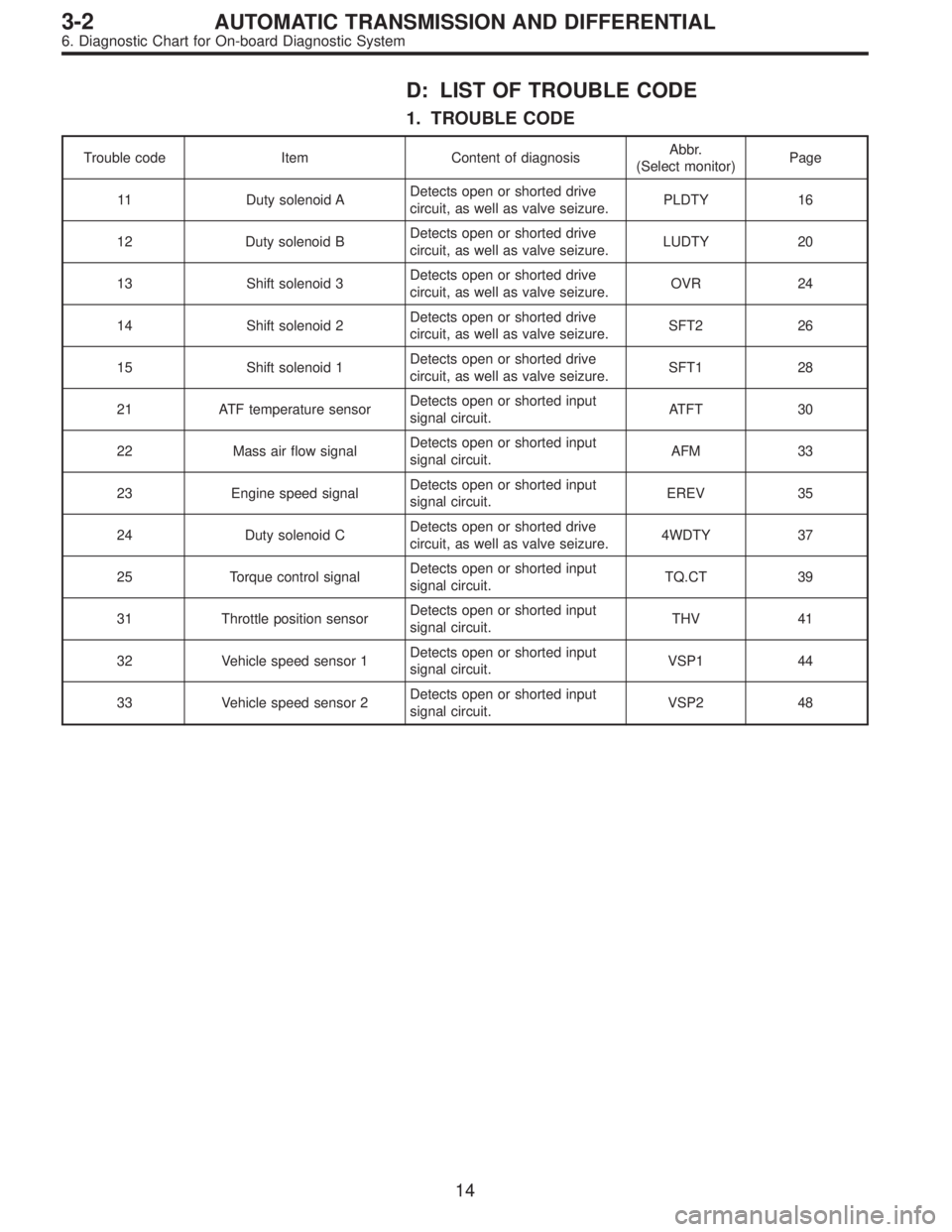
D: LIST OF TROUBLE CODE
1. TROUBLE CODE
Trouble code Item Content of diagnosisAbbr.
(Select monitor)Page
11 Duty solenoid ADetects open or shorted drive
circuit, as well as valve seizure.PLDTY 16
12 Duty solenoid BDetects open or shorted drive
circuit, as well as valve seizure.LUDTY 20
13 Shift solenoid 3Detects open or shorted drive
circuit, as well as valve seizure.OVR 24
14 Shift solenoid 2Detects open or shorted drive
circuit, as well as valve seizure.SFT2 26
15 Shift solenoid 1Detects open or shorted drive
circuit, as well as valve seizure.SFT1 28
21 ATF temperature sensorDetects open or shorted input
signal circuit.ATFT 30
22 Mass air flow signalDetects open or shorted input
signal circuit.AFM 33
23 Engine speed signalDetects open or shorted input
signal circuit.EREV 35
24 Duty solenoid CDetects open or shorted drive
circuit, as well as valve seizure.4WDTY 37
25 Torque control signalDetects open or shorted input
signal circuit.TQ.CT 39
31 Throttle position sensorDetects open or shorted input
signal circuit.THV 41
32 Vehicle speed sensor 1Detects open or shorted input
signal circuit.VSP1 44
33 Vehicle speed sensor 2Detects open or shorted input
signal circuit.VSP2 48
14
3-2AUTOMATIC TRANSMISSION AND DIFFERENTIAL
6. Diagnostic Chart for On-board Diagnostic System
Page 2419 of 3342

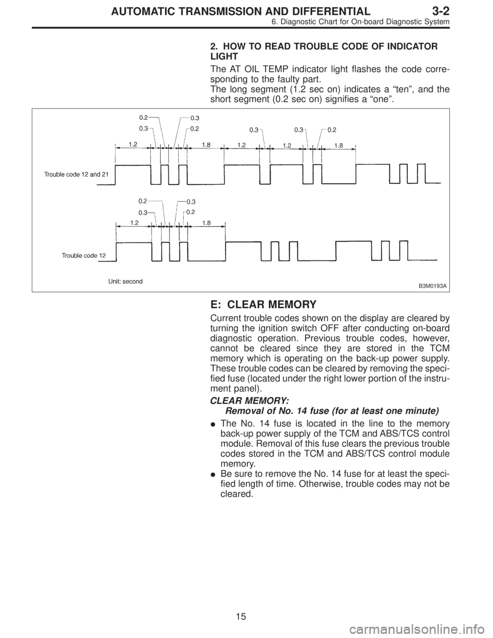
2. HOW TO READ TROUBLE CODE OF INDICATOR
LIGHT
The AT OIL TEMP indicator light flashes the code corre-
sponding to the faulty part.
The long segment (1.2 sec on) indicates a“ten”, and the
short segment (0.2 sec on) signifies a“one”.
B3M0193A
E: CLEAR MEMORY
Current trouble codes shown on the display are cleared by
turning the ignition switch OFF after conducting on-board
diagnostic operation. Previous trouble codes, however,
cannot be cleared since they are stored in the TCM
memory which is operating on the back-up power supply.
These trouble codes can be cleared by removing the speci-
fied fuse (located under the right lower portion of the instru-
ment panel).
CLEAR MEMORY:
Removal of No. 14 fuse (for at least one minute)
�The No. 14 fuse is located in the line to the memory
back-up power supply of the TCM and ABS/TCS control
module. Removal of this fuse clears the previous trouble
codes stored in the TCM and ABS/TCS control module
memory.
�Be sure to remove the No. 14 fuse for at least the speci-
fied length of time. Otherwise, trouble codes may not be
cleared.
15
3-2AUTOMATIC TRANSMISSION AND DIFFERENTIAL
6. Diagnostic Chart for On-board Diagnostic System
Page 2420 of 3342
7. Diagnostic Chart with Trouble Code
A: TROUBLE CODE 11
—DUTY SOLENOID A—
DIAGNOSIS:
Output signal circuit of duty solenoid A or resistor is open
or shorted.
TROUBLE SYMPTOM:
Excessive shift shock
1. Check harnesses and connectors between
TCM and duty solenoid A and between
resistor.
OK
�Not OK
Repair or replace harness connectors.
2. Check duty solenoid A’s ground line.
OK
�Not OK
Repair ground line.
3. Check resistor.
OK
�Not OK
Check and replace resistor if necessary.
4. Check duty solenoid A.
OK
�Not OK
Replace duty solenoid A.
5. Check output signal emitted from TCM.
OK
�Not OK
�Repair TCM connector terminal poor contact.
�Replace TCM.
�Repair TCM connector terminal poor contact.
OBD0424
�
�
�
�
�
16
3-2AUTOMATIC TRANSMISSION AND DIFFERENTIAL
7. Diagnostic Chart with Trouble Code
Page 2421 of 3342

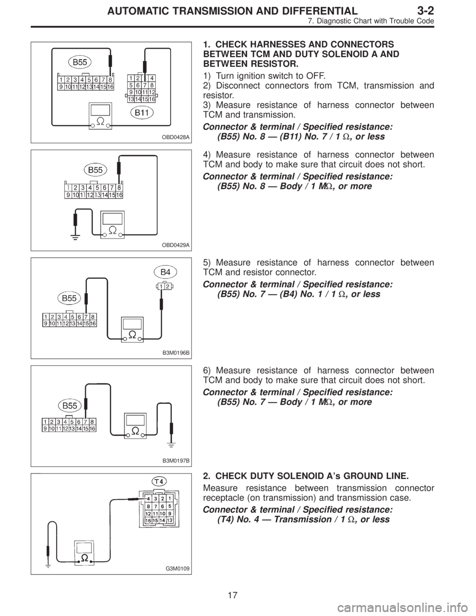
OBD0428A
1. CHECK HARNESSES AND CONNECTORS
BETWEEN TCM AND DUTY SOLENOID A AND
BETWEEN RESISTOR.
1) Turn ignition switch to OFF.
2) Disconnect connectors from TCM, transmission and
resistor.
3) Measure resistance of harness connector between
TCM and transmission.
Connector & terminal / Specified resistance:
(B55) No. 8 — (B11) No.7/1Ω, or less
OBD0429A
4) Measure resistance of harness connector between
TCM and body to make sure that circuit does not short.
Connector & terminal / Specified resistance:
(B55) No. 8 — Body/1MΩ, or more
B3M0196B
5) Measure resistance of harness connector between
TCM and resistor connector.
Connector & terminal / Specified resistance:
(B55) No. 7 — (B4) No.1/1Ω, or less
B3M0197B
6) Measure resistance of harness connector between
TCM and body to make sure that circuit does not short.
Connector & terminal / Specified resistance:
(B55) No. 7 — Body/1MΩ, or more
G3M0109
2. CHECK DUTY SOLENOID A’s GROUND LINE.
Measure resistance between transmission connector
receptacle (on transmission) and transmission case.
Connector & terminal / Specified resistance:
(T4) No. 4 — Transmission / 1Ω, or less
17
3-2AUTOMATIC TRANSMISSION AND DIFFERENTIAL
7. Diagnostic Chart with Trouble Code
Page 2422 of 3342

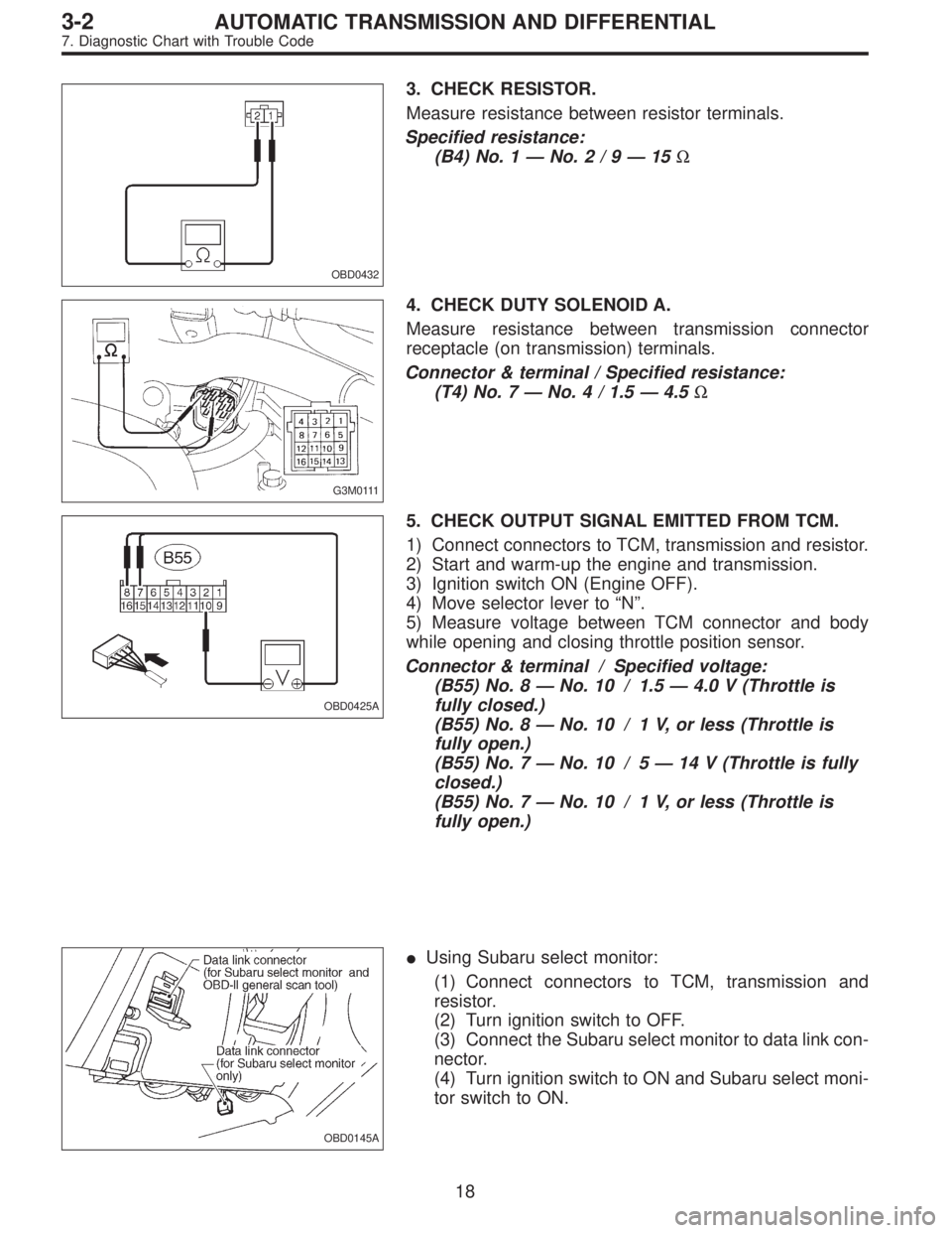
OBD0432
3. CHECK RESISTOR.
Measure resistance between resistor terminals.
Specified resistance:
(B4) No. 1—No.2/9—15Ω
G3M0111
4. CHECK DUTY SOLENOID A.
Measure resistance between transmission connector
receptacle (on transmission) terminals.
Connector & terminal / Specified resistance:
(T4) No. 7—No. 4 / 1.5—4.5Ω
OBD0425A
5. CHECK OUTPUT SIGNAL EMITTED FROM TCM.
1) Connect connectors to TCM, transmission and resistor.
2) Start and warm-up the engine and transmission.
3) Ignition switch ON (Engine OFF).
4) Move selector lever to“N”.
5) Measure voltage between TCM connector and body
while opening and closing throttle position sensor.
Connector & terminal / Specified voltage:
(B55) No. 8—No. 10 / 1.5—4.0 V (Throttle is
fully closed.)
(B55) No. 8—No. 10 / 1 V, or less (Throttle is
fully open.)
(B55) No. 7—No. 10 / 5—14 V (Throttle is fully
closed.)
(B55) No. 7—No. 10 / 1 V, or less (Throttle is
fully open.)
OBD0145A
�Using Subaru select monitor:
(1) Connect connectors to TCM, transmission and
resistor.
(2) Turn ignition switch to OFF.
(3) Connect the Subaru select monitor to data link con-
nector.
(4) Turn ignition switch to ON and Subaru select moni-
tor switch to ON.
18
3-2AUTOMATIC TRANSMISSION AND DIFFERENTIAL
7. Diagnostic Chart with Trouble Code