Page 1982 of 3342
![SUBARU LEGACY 1997 Service Repair Manual DTC
No.Abbreviation
(Subaru Select Monitor)Item Page
P1120 ST
—SWON Starter switch circuit high input 348
P1121 N
—SWON Neutral position switch circuit low input [AT vehicles] 350
P1122 BR
—HI P](/manual-img/17/57434/w960_57434-1981.png "SUBARU LEGACY 1997 Service Repair Manual DTC
No.Abbreviation
(Subaru Select Monitor)Item Page
P1120 ST
—SWON Starter switch circuit high input 348
P1121 N
—SWON Neutral position switch circuit low input [AT vehicles] 350
P1122 BR
—HI P")
DTC
No.Abbreviation
(Subaru Select Monitor)Item Page
P1120 ST
—SWON Starter switch circuit high input 348
P1121 N
—SWON Neutral position switch circuit low input [AT vehicles] 350
P1122 BR
—HI Pressure sources switching solenoid valve circuit high input 354
P1124 TCS
—HI TCS signal circuit high input 357
P1141 QA
—RHI Mass air flow sensor circuit range/performance problem (high input) 360
P1142 TH
—RLOW Throttle position sensor circuit range/performance problem (low input) 362
P1143 PS
—RLOW Pressure sensor circuit range/performance problem (low input) 364
P1144 PS
—RHI Pressure sensor circuit range/performance problem (high input) 368
P1400 PCVSOL
—LO Fuel tank pressure control solenoid valve circuit low input 370
P1420 PCVSOL
—HI Fuel tank pressure control solenoid valve circuit high input 374
P1421 EGRSOL
—HI Exhaust gas recirculation circuit high input 377
P1422 CPC
—HI Evaporative emission control system purge control valve circuit high input 380
P1423 VCMSOL
—HI Evaporative emission control system vent control high input 383
P1440 PCV
—FLOW Fuel tank pressure control system function problem (low input) 386
P1441 PCV
—FHI Fuel tank pressure control system function problem (high input) 390
P1442 FLVL
—R2 Fuel level sensor circuit range/performance problem 2 393
P1500 FAN
—1 Radiator fan relay 1 circuit low input 395
P1502 FAN
—F Radiator fan function problem 401
P1507 ISC
—SHI Idle control system malfunction (fail-safe) 403
P1520 FAN
—1HI Radiator fan relay 1 circuit high input 405
P1540 VSP
—S Vehicle speed sensor malfunction 2 407
P1700 ATTH Throttle position sensor circuit malfunction for automatic transmission 409
P1701 ATCRS Cruise control set signal circuit malfunction for automatic transmission 411
P1702 ATDIAG
—LO Automatic transmission diagnosis input signal circuit low input 413
P1722 ATDIAG
—HI Automatic transmission diagnosis input signal circuit high input 416
P1742 ATDIAG
—2 Automatic transmission diagnosis input signal circuit malfunction 419
131
2-7ON-BOARD DIAGNOSTICS II SYSTEM
10. Diagnostic Chart with Trouble Code for LHD Vehicles
Page 2167 of 3342
![SUBARU LEGACY 1997 Service Repair Manual 10BP2CHECK THROTTLE POSITION SENSOR
CIRCUIT.
Check throttle position sensor circuit. <Ref. to 3-2 [T7K0].>
: Is there any trouble in throttle position sen-
sor circuit?
: Repair or replace throttle po](/manual-img/17/57434/w960_57434-2166.png "SUBARU LEGACY 1997 Service Repair Manual 10BP2CHECK THROTTLE POSITION SENSOR
CIRCUIT.
Check throttle position sensor circuit. <Ref. to 3-2 [T7K0].>
: Is there any trouble in throttle position sen-
sor circuit?
: Repair or replace throttle po")
10BP2CHECK THROTTLE POSITION SENSOR
CIRCUIT.
Check throttle position sensor circuit.
: Is there any trouble in throttle position sen-
sor circuit?
: Repair or replace throttle position sensor circuit.
: Go to step10BP3.
10BP3CHECK VEHICLE SPEED SENSOR 1 CIR-
CUIT.
Check vehicle speed sensor 1 circuit.
: Is there any trouble in vehicle speed sensor
1 circuit?
: Repair or replace vehicle speed sensor 1 circuit.
: Go to step10BP4.
10BP4CHECK VEHICLE SPEED SENSOR 2 CIR-
CUIT.
Check vehicle speed sensor 2 circuit.
: Is there any trouble in vehicle speed sensor
2 circuit?
: Repair or replace vehicle speed sensor 2 circuit.
: Go to step10BP5.
10BP5
CHECK ENGINE SPEED INPUT CIRCUIT.
Check engine speed input circuit.
: Is there any trouble in engine speed input
circuit?
: Repair or replace engine speed input circuit.
: Go to next.
: Is there poor contact in TCM connector?
: Repair poor contact in TCM connector.
: Go to next.
: Is there any mechanical trouble in automatic
transmission?
: Repair or replace automatic transmission.
: Replace TCM.
316
2-7ON-BOARD DIAGNOSTICS II SYSTEM
10. Diagnostic Chart with Trouble Code for LHD Vehicles
Page 2171 of 3342
10BQ9CHECK ATF TEMPERATURE SENSOR
CIRCUIT.
Check ATF temperature sensor circuit.
[T7F0].>
: Is there any trouble in ATF temperature sen-
sor circuit?
: Repair or replace ATF temperature sensor circuit.
: Go to next.
: Is there poor contact in TCM connector?
: Repair poor contact in TCM connector.
: Go to next.
: Is there any mechanical trouble in automatic
transmission?
: Repair or replace automatic transmission.
: Replace TCM.
320
2-7ON-BOARD DIAGNOSTICS II SYSTEM
10. Diagnostic Chart with Trouble Code for LHD Vehicles
Page 2178 of 3342

: Is there any mechanical trouble in automatic
transmission?
: Repair or replace automatic transmission.
: Replace TCM.
10BV4
CHECK SHIFT SOLENOID 1 CIRCUIT.
Check shift solenoid 1 circuit.
: Is there any trouble in shift solenoid 1 cir-
cuit?
: Repair or replace shift solenoid 1 circuit.
: Go to step10BV5.
10BV5
CHECK SHIFT SOLENOID 2 CIRCUIT.
Check shift solenoid 2 circuit.
: Is there any trouble in shift solenoid 2 cir-
cuit?
: Repair or replace shift solenoid 2 circuit.
: Go to step10BV6.
10BV6
CHECK SHIFT SOLENOID 3 CIRCUIT.
Check shift solenoid 3 circuit.
: Is there any trouble in shift solenoid 3 cir-
cuit?
: Repair or replace shift solenoid 3 circuit.
: Go to next.
: Is there poor contact in TCM connector?
: Repair poor contact in TCM connector.
: Go to next.
: Is there any mechanical trouble in automatic
transmission?
: Repair or replace automatic transmission.
: Replace TCM.
327
2-7ON-BOARD DIAGNOSTICS II SYSTEM
10. Diagnostic Chart with Trouble Code for LHD Vehicles
Page 2260 of 3342
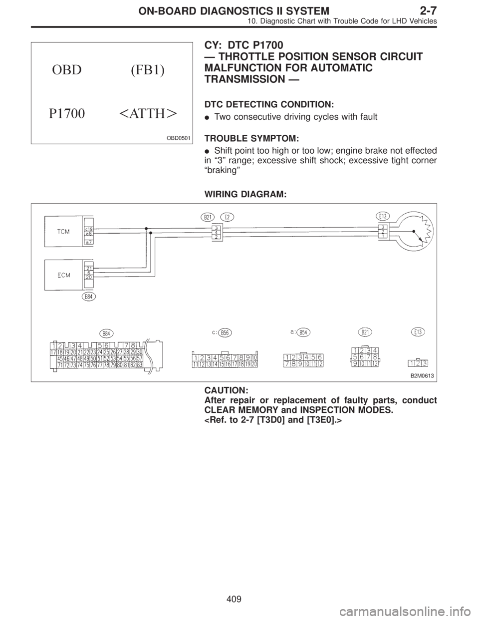
OBD0501
CY: DTC P1700
—THROTTLE POSITION SENSOR CIRCUIT
MALFUNCTION FOR AUTOMATIC
TRANSMISSION—
DTC DETECTING CONDITION:
�Two consecutive driving cycles with fault
TROUBLE SYMPTOM:
�Shift point too high or too low; engine brake not effected
in“3”range; excessive shift shock; excessive tight corner
“braking”
WIRING DIAGRAM:
B2M0613
CAUTION:
After repair or replacement of faulty parts, conduct
CLEAR MEMORY and INSPECTION MODES.
409
2-7ON-BOARD DIAGNOSTICS II SYSTEM
10. Diagnostic Chart with Trouble Code for LHD Vehicles
Page 2262 of 3342
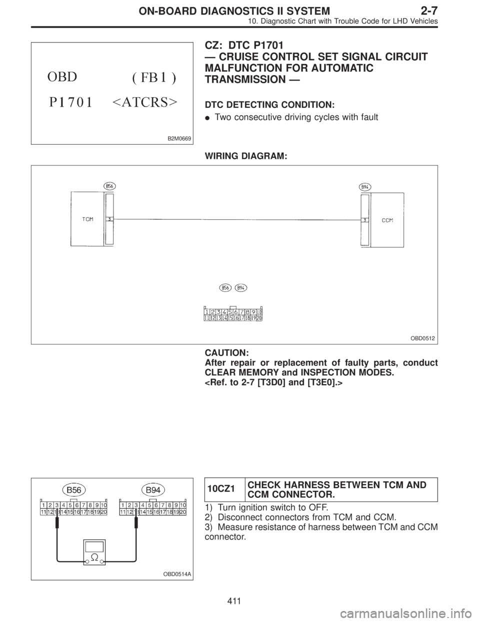
B2M0669
CZ: DTC P1701
—CRUISE CONTROL SET SIGNAL CIRCUIT
MALFUNCTION FOR AUTOMATIC
TRANSMISSION—
DTC DETECTING CONDITION:
�Two consecutive driving cycles with fault
WIRING DIAGRAM:
OBD0512
CAUTION:
After repair or replacement of faulty parts, conduct
CLEAR MEMORY and INSPECTION MODES.
OBD0514A
10CZ1CHECK HARNESS BETWEEN TCM AND
CCM CONNECTOR.
1) Turn ignition switch to OFF.
2) Disconnect connectors from TCM and CCM.
3) Measure resistance of harness between TCM and CCM
connector.
411
2-7ON-BOARD DIAGNOSTICS II SYSTEM
10. Diagnostic Chart with Trouble Code for LHD Vehicles
Page 2264 of 3342
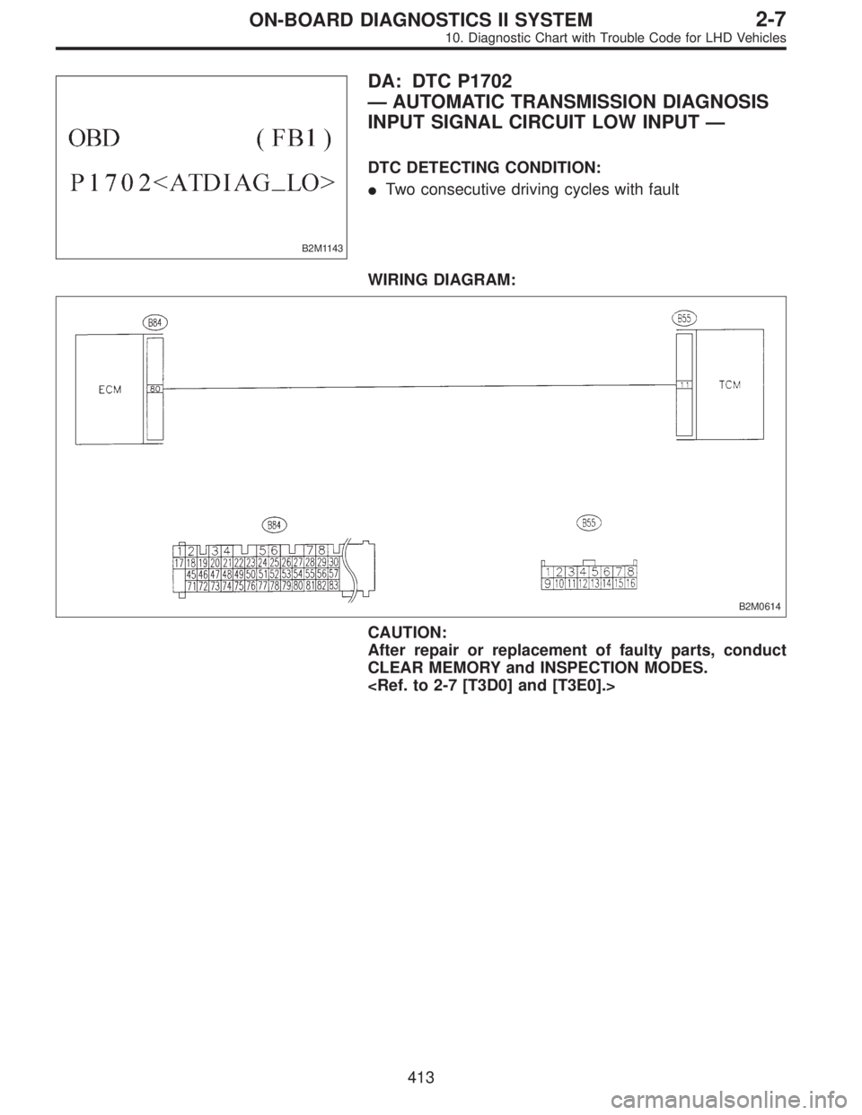
B2M1143
DA: DTC P1702
—AUTOMATIC TRANSMISSION DIAGNOSIS
INPUT SIGNAL CIRCUIT LOW INPUT—
DTC DETECTING CONDITION:
�Two consecutive driving cycles with fault
WIRING DIAGRAM:
B2M0614
CAUTION:
After repair or replacement of faulty parts, conduct
CLEAR MEMORY and INSPECTION MODES.
413
2-7ON-BOARD DIAGNOSTICS II SYSTEM
10. Diagnostic Chart with Trouble Code for LHD Vehicles
Page 2267 of 3342
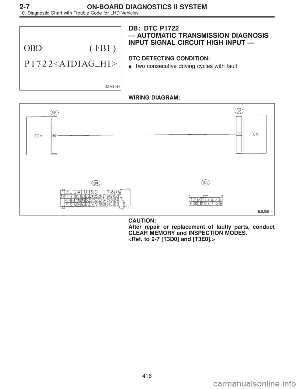
B2M1144
DB: DTC P1722
—AUTOMATIC TRANSMISSION DIAGNOSIS
INPUT SIGNAL CIRCUIT HIGH INPUT—
DTC DETECTING CONDITION:
�Two consecutive driving cycles with fault
WIRING DIAGRAM:
B2M0614
CAUTION:
After repair or replacement of faulty parts, conduct
CLEAR MEMORY and INSPECTION MODES.
416
2-7ON-BOARD DIAGNOSTICS II SYSTEM
10. Diagnostic Chart with Trouble Code for LHD Vehicles
![SUBARU LEGACY 1997 Service Repair Manual 10BQ9CHECK ATF TEMPERATURE SENSOR
CIRCUIT.
Check ATF temperature sensor circuit. <Ref. to 3-2
[T7F0].>
: Is there any trouble in ATF temperature sen-
sor circuit?
: Repair or replace ATF temperature s](/manual-img/17/57434/w960_57434-2170.png "SUBARU LEGACY 1997 Service Repair Manual 10BQ9CHECK ATF TEMPERATURE SENSOR
CIRCUIT.
Check ATF temperature sensor circuit. <Ref. to 3-2
[T7F0].>
: Is there any trouble in ATF temperature sen-
sor circuit?
: Repair or replace ATF temperature s")