Page 2270 of 3342
B2M1147
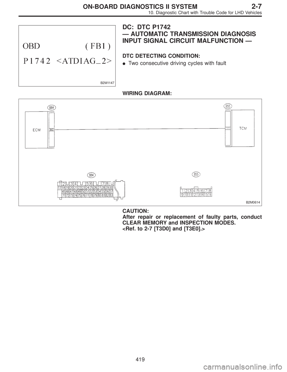
DC: DTC P1742
—AUTOMATIC TRANSMISSION DIAGNOSIS
INPUT SIGNAL CIRCUIT MALFUNCTION—
DTC DETECTING CONDITION:
�Two consecutive driving cycles with fault
WIRING DIAGRAM:
B2M0614
CAUTION:
After repair or replacement of faulty parts, conduct
CLEAR MEMORY and INSPECTION MODES.
419
2-7ON-BOARD DIAGNOSTICS II SYSTEM
10. Diagnostic Chart with Trouble Code for LHD Vehicles
Page 2276 of 3342
Item Page
P1122 BR
—HI Pressure sources switching solenoid valve circuit high input 523
P1141 QA
—RHI Mass air flow sensor circuit range/performance prob")
DTC
No.Abbreviation
(Subaru Select Monitor)Item Page
P1122 BR
—HI Pressure sources switching solenoid valve circuit high input 523
P1141 QA
—RHI Mass air flow sensor circuit range/performance problem (high input) 524
P1142 TH
—RLOW Throttle position sensor circuit range/performance problem (low input) 525
P1143 PS
—RLOW Pressure sensor circuit range/performance problem (low input) 526
P1144 PS
—RHI Pressure sensor circuit range/performance problem (high input) 527
P1400 PCVSOL
—LO Fuel tank pressure control solenoid valve circuit low input 528
P1420 PCVSOL
—HI Fuel tank pressure control solenoid valve circuit high input 532
P1421 EGRSOL
—HI Exhaust gas recirculation circuit high input 535
P1422 CPC
—HI Evaporative emission control system purge control valve circuit high input 536
P1423 VCMSOL
—HI Evaporative emission control system vent control high input 537
P1440 PCV
—FLOW Fuel tank pressure control system function problem (low input) 540
P1441 PCV
—FHI Fuel tank pressure control system function problem (high input) 541
P1442 FLVL
—R2 Fuel level sensor circuit range/performance problem 2 542
P1500 FAN
—1 Radiator fan relay 1 circuit low input 544
P1502 FAN
—F Radiator fan function problem 545
P1507 ISC
—SHI Idle control system malfunction (fail-safe) 546
P1520 FAN
—1HI Radiator fan relay 1 circuit high input 547
P1540 VSP
—S Vehicle speed sensor malfunction 2 548
P1700 ATTH Throttle position sensor circuit malfunction for automatic transmission 549
P1701 ATCRS Cruise control set signal circuit malfunction for automatic transmission 550
P1702 ATDIAG
—LO Automatic transmission diagnosis input signal circuit low input 551
P1722 ATDIAG
—HI Automatic transmission diagnosis input signal circuit high input 552
P1742 ATDIAG
—2 Automatic transmission diagnosis input signal circuit malfunction 553
425
2-7ON-BOARD DIAGNOSTICS II SYSTEM
11. Diagnostic Chart with Trouble Code for RHD Vehicles
Page 2356 of 3342
OBD0380
BJ: DTC P0710
—TRANSMISSION FLUID TEMPERATURE
SENSOR CIRCUIT MALFUNCTION—
WIRING DIAGRAM:
OBD0383
NOTE:
Check automatic transmission fluid temperature sensor cir-
cuit.
505
2-7ON-BOARD DIAGNOSTICS II SYSTEM
11. Diagnostic Chart with Trouble Code for RHD Vehicles
Page 2402 of 3342
B2M1143
CX: DTC P1702
—AUTOMATIC TRANSMISSION DIAGNOSIS
INPUT SIGNAL CIRCUIT LOW INPUT—
WIRING DIAGRAM:
B2M0614
NOTE:
Check automatic transmission diagnosis input signal cir-
cuit.
551
2-7ON-BOARD DIAGNOSTICS II SYSTEM
11. Diagnostic Chart with Trouble Code for RHD Vehicles
Page 2403 of 3342
B2M1144
CY: DTC P1722
—AUTOMATIC TRANSMISSION DIAGNOSIS
INPUT SIGNAL CIRCUIT HIGH INPUT—
WIRING DIAGRAM:
B2M0614
NOTE:
Check automatic transmission diagnosis input signal cir-
cuit.
552
2-7ON-BOARD DIAGNOSTICS II SYSTEM
11. Diagnostic Chart with Trouble Code for RHD Vehicles
Page 2404 of 3342
B2M1147
CZ: DTC P1742
—AUTOMATIC TRANSMISSION DIAGNOSIS
INPUT SIGNAL CIRCUIT MALFUNCTION—
WIRING DIAGRAM:
B2M0614
NOTE:
Check automatic transmission diagnosis input signal cir-
cuit.
553
2-7ON-BOARD DIAGNOSTICS II SYSTEM
11. Diagnostic Chart with Trouble Code for RHD Vehicles
Page 2405 of 3342
1. Supplemental Restraint System
“Airbag”
Airbag system wiring harness is routed near the transmis-
sion control module (TCM).
�All Airbag system wiring harness and connectors
are colored yellow. Do not use electrical test equip-
ment on these circuit.
�Be careful not to damage Airbag system wiring har-
ness when performing diagnostics and servicing the
TCM.
B3M0173A
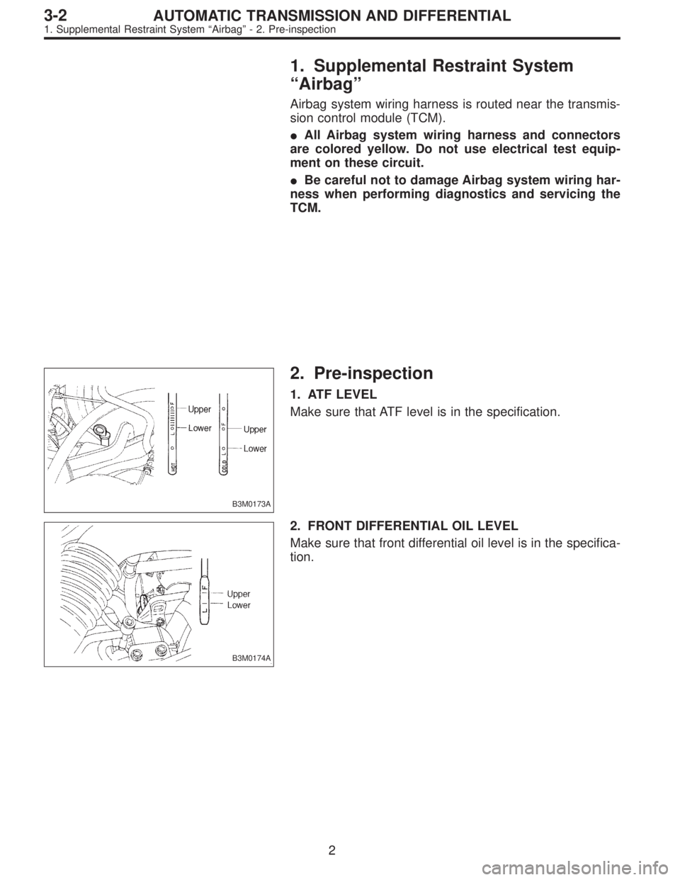
2. Pre-inspection
1. ATF LEVEL
Make sure that ATF level is in the specification.
B3M0174A
2. FRONT DIFFERENTIAL OIL LEVEL
Make sure that front differential oil level is in the specifica-
tion.
2
3-2AUTOMATIC TRANSMISSION AND DIFFERENTIAL
1. Supplemental Restraint System“Airbag”- 2. Pre-inspection
Page 2406 of 3342
1. Supplemental Restraint System
“Airbag”
Airbag system wiring harness is routed near the transmis-
sion control module (TCM).
�All Airbag system wiring harness and connectors
are colored yellow. Do not use electrical test equip-
ment on these circuit.
�Be careful not to damage Airbag system wiring har-
ness when performing diagnostics and servicing the
TCM.
B3M0173A
2. Pre-inspection
1. ATF LEVEL
Make sure that ATF level is in the specification.
B3M0174A
2. FRONT DIFFERENTIAL OIL LEVEL
Make sure that front differential oil level is in the specifica-
tion.
2
3-2AUTOMATIC TRANSMISSION AND DIFFERENTIAL
1. Supplemental Restraint System“Airbag”- 2. Pre-inspection