1997 SSANGYONG KORANDO wheel torque
[x] Cancel search: wheel torquePage 1488 of 2053
SSANGYONG MY2002
6E-2 POWER STEERING AND COLUMN
GENERAL DESCRIPTION
Caution: To ensure the energy-absorbing action of
the steering column, it is important to use only the
specified screws, bolts, and nuts, tightened to the
specified torque.
In addition to the steering function, the steering column
provides safety and security.
The energy-absorbing column is designed to compress
in a front-end collision to lessen the chance of driver
injury.
The ignition switch and the lock are mounted on the
column, allowing the ignition and steering operations
to be locked to inhibit theft of the car.
The column levers trigger the turn signals, the headlight
beams, and the windshield washer and wipers.
A tilt steering column uses a spherical joint to allow
the steering wheel to tilt up and down. This enables
the driver to adjust the steering wheel to a comfortable
position.
Notice: Apply a thin coat of lithium grease to all friction
points when reassembling.
The column may be disassembled and reassembled
easily.
DESCRIPTION AND OPERATION
IGNITION SWITCH KEYHOLE LAMP
For description and lamp replacement information, Re-
fer to Section 9B, Lighting Systems.
IGNITION KEY REMINDER
The ignition key reminder alerts the driver that the key
is still in the ignition when the driver attempts to exit
the vehicle.
An internal switch in the ignition lock cylinder supplies
battery voltage to the reminder chime module when all
of the following conditions are true:
•The key is in the ignition switch.
The ignition is OFF.
The driver’s door is open.
For information on removal and installation of the re-
minder chime module, Refer to Section 9E, Instrumen-
tation/Driver Information.
Page 1496 of 2053
SSANGYONG MY2002
6E-10 POWER STEERING AND COLUMN
KAA6E060
KAA6E080
KAA6E070
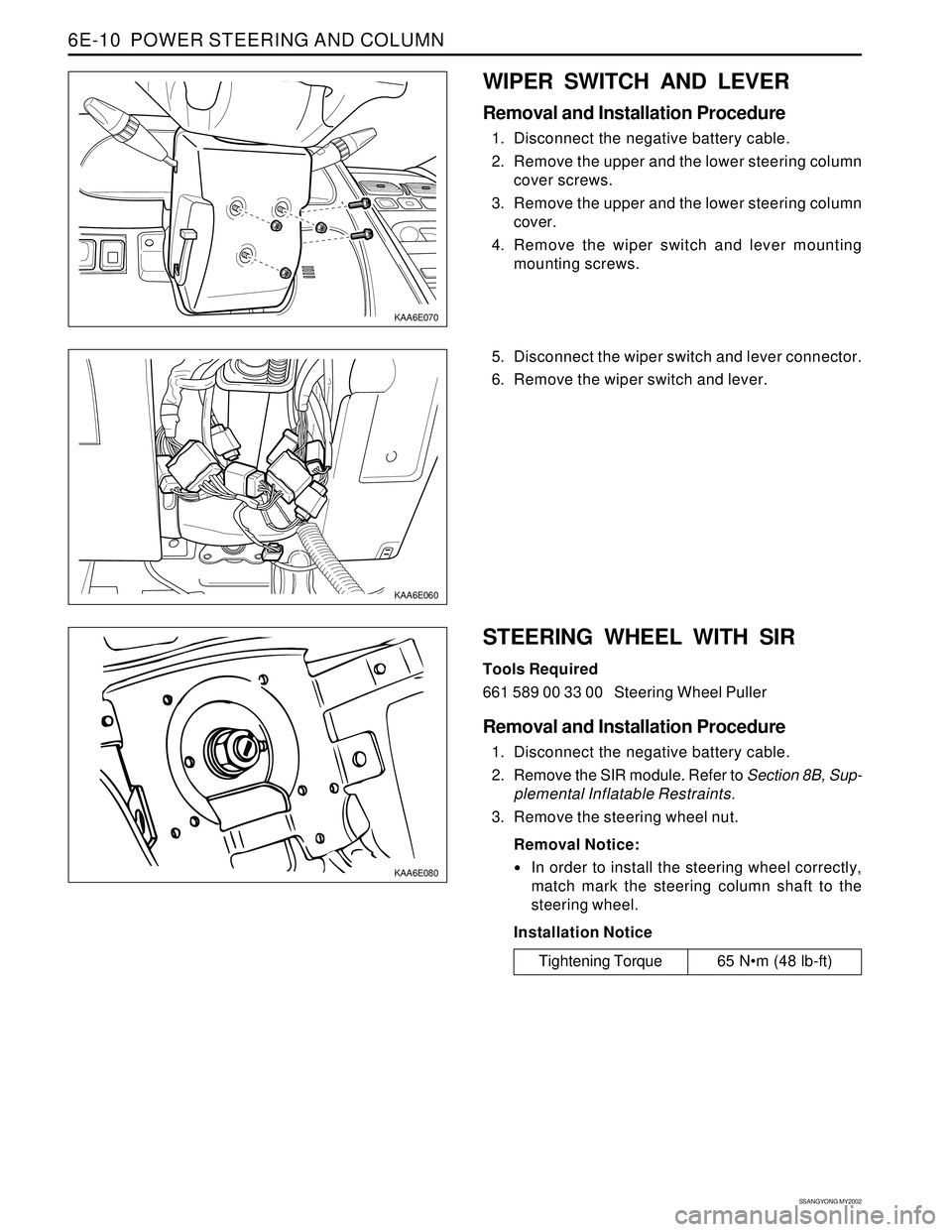
WIPER SWITCH AND LEVER
Removal and Installation Procedure
1. Disconnect the negative battery cable.
2. Remove the upper and the lower steering column
cover screws.
3. Remove the upper and the lower steering column
cover.
4. Remove the wiper switch and lever mounting
mounting screws.
Tightening Torque 65 Nm (48 lb-ft) 5. Disconnect the wiper switch and lever connector.
6. Remove the wiper switch and lever.
STEERING WHEEL WITH SIR
Tools Required
661 589 00 33 00 Steering Wheel Puller
Removal and Installation Procedure
1. Disconnect the negative battery cable.
2. Remove the SIR module. Refer to Section 8B, Sup-
plemental Inflatable Restraints.
3. Remove the steering wheel nut.
Removal Notice:
In order to install the steering wheel correctly,
match mark the steering column shaft to the
steering wheel.
Installation Notice
Page 1498 of 2053
SSANGYONG MY2002
6E-12 POWER STEERING AND COLUMN
KAA6E040
KAA6E120
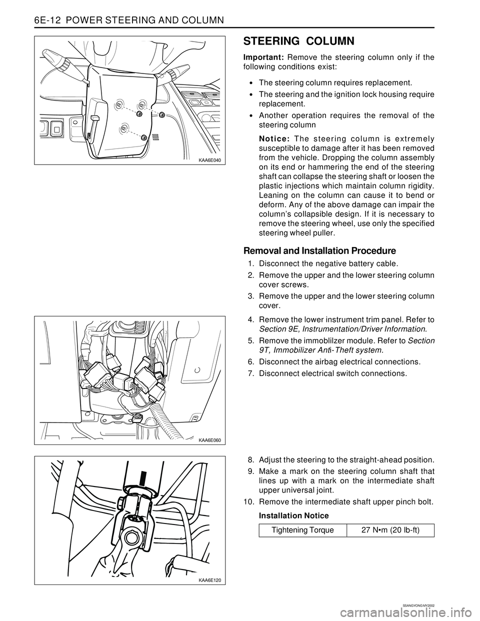
STEERING COLUMN
Important: Remove the steering column only if the
following conditions exist:
The steering column requires replacement.
The steering and the ignition lock housing require
replacement.
Another operation requires the removal of the
steering column
Notice: The steering column is extremely
susceptible to damage after it has been removed
from the vehicle. Dropping the column assembly
on its end or hammering the end of the steering
shaft can collapse the steering shaft or loosen the
plastic injections which maintain column rigidity.
Leaning on the column can cause it to bend or
deform. Any of the above damage can impair the
column’s collapsible design. If it is necessary to
remove the steering wheel, use only the specified
steering wheel puller.
Removal and Installation Procedure
1. Disconnect the negative battery cable.
2. Remove the upper and the lower steering column
cover screws.
3. Remove the upper and the lower steering column
cover.
KAA6E060
4. Remove the lower instrument trim panel. Refer to
Section 9E, Instrumentation/Driver Information.
5. Remove the immoblilzer module. Refer to Section
9T, Immobilizer Anti-Theft system.
6. Disconnect the airbag electrical connections.
7. Disconnect electrical switch connections.
8. Adjust the steering to the straight-ahead position.
9. Make a mark on the steering column shaft that
lines up with a mark on the intermediate shaft
upper universal joint.
10. Remove the intermediate shaft upper pinch bolt.
Installation Notice
Tightening Torque 27 Nm (20 lb-ft)
Page 1642 of 2053

SSANGYONG MY2002
8B-60 SUPPLEMENTAL RESTRAINTS SYSTEM
KAA8B140
DRIVER AIRBAG MODULE
Removal and installation Procedure
1. Disconnect the negative battery cable.
Caution: The SDM can maintain sufficient
voltage to deploy the airbags for 0.15 seconds
after the Ignition is OFF and the airbag fuse has
been removed. If the airbags are not
disconnected, service cannot begin until one
minute has passed after disconnecting power
to the SDM. If the airbags are disconnected,
service can begin immediately without waiting
for one-minute time period to expire. Failure to
temporarily disable the SRS during service
result in unexpected deployment, personal
injury, and otherwise unneeded SRS repair.
2. Disable the supplemental restraint system (SRS).
Refer to “Disabling the SRS” in this section.
3. Position the steering wheel straight ahead.
4. Remove the driver airbag module mounting bolts.
Installation Notice
Caution: When handling an airbag module,
always keeps the top of the unit facing upward.
This leaves room for the airbag to expand if the
module unexpectedly deploys. Without room
for expansion, a module suddenly propelled
toward a person or object can cause injury or
vehicle damage.
5. Remove the connector from the horn terminal and
the driver airbag module.
6. Remove the driver airbag module.
7. Installation should follow the removal procedure
in the reverse order.
Tightening Torque 8 Nm (71 lb-in)
Page 1643 of 2053
SUPPLEMENTAL RESTRAINTS SYSTEM 8B-61
SSANGYONG MY2002
KAA8B050
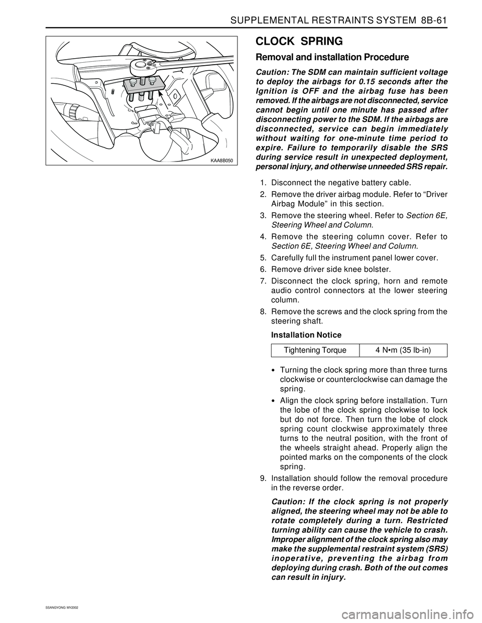
CLOCK SPRING
Removal and installation Procedure
Caution: The SDM can maintain sufficient voltage
to deploy the airbags for 0.15 seconds after the
Ignition is OFF and the airbag fuse has been
removed. If the airbags are not disconnected, service
cannot begin until one minute has passed after
disconnecting power to the SDM. If the airbags are
disconnected, service can begin immediately
without waiting for one-minute time period to
expire. Failure to temporarily disable the SRS
during service result in unexpected deployment,
personal injury, and otherwise unneeded SRS repair.
1. Disconnect the negative battery cable.
2. Remove the driver airbag module. Refer to “Driver
Airbag Module” in this section.
3. Remove the steering wheel. Refer to Section 6E,
Steering Wheel and Column.
4. Remove the steering column cover. Refer to
Section 6E, Steering Wheel and Column.
5. Carefully full the instrument panel lower cover.
6. Remove driver side knee bolster.
7. Disconnect the clock spring, horn and remote
audio control connectors at the lower steering
column.
8. Remove the screws and the clock spring from the
steering shaft.
Installation Notice
Turning the clock spring more than three turns
clockwise or counterclockwise can damage the
spring.
Align the clock spring before installation. Turn
the lobe of the clock spring clockwise to lock
but do not force. Then turn the lobe of clock
spring count clockwise approximately three
turns to the neutral position, with the front of
the wheels straight ahead. Properly align the
pointed marks on the components of the clock
spring.
9. Installation should follow the removal procedure
in the reverse order.
Caution: If the clock spring is not properly
aligned, the steering wheel may not be able to
rotate completely during a turn. Restricted
turning ability can cause the vehicle to crash.
Improper alignment of the clock spring also may
make the supplemental restraint system (SRS)
inoperative, preventing the airbag from
deploying during crash. Both of the out comes
can result in injury.
Tightening Torque 4 Nm (35 lb-in)
Page 1714 of 2053
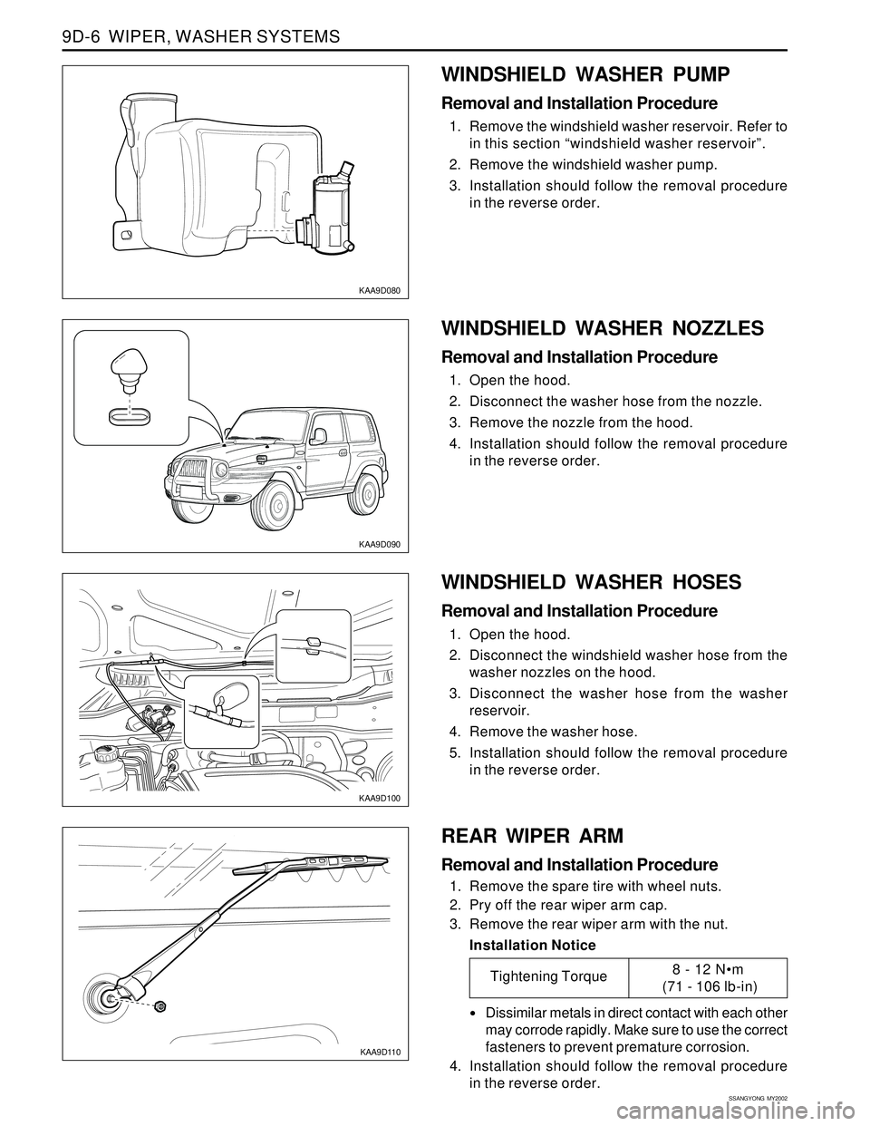
SSANGYONG MY2002
9D-6 WIPER, WASHER SYSTEMS
KAA9D080
KAA9D090
KAA9D100
WINDSHIELD WASHER PUMP
Removal and Installation Procedure
1. Remove the windshield washer reservoir. Refer to
in this section “windshield washer reservoir”.
2. Remove the windshield washer pump.
3. Installation should follow the removal procedure
in the reverse order.
WINDSHIELD WASHER HOSES
Removal and Installation Procedure
1. Open the hood.
2. Disconnect the windshield washer hose from the
washer nozzles on the hood.
3. Disconnect the washer hose from the washer
reservoir.
4. Remove the washer hose.
5. Installation should follow the removal procedure
in the reverse order.
KAA9D110
REAR WIPER ARM
Removal and Installation Procedure
1. Remove the spare tire with wheel nuts.
2. Pry off the rear wiper arm cap.
3. Remove the rear wiper arm with the nut.
Installation Notice
Dissimilar metals in direct contact with each other
may corrode rapidly. Make sure to use the correct
fasteners to prevent premature corrosion.
4. Installation should follow the removal procedure
in the reverse order.
WINDSHIELD WASHER NOZZLES
Removal and Installation Procedure
1. Open the hood.
2. Disconnect the washer hose from the nozzle.
3. Remove the nozzle from the hood.
4. Installation should follow the removal procedure
in the reverse order.
Tightening Torque8 - 12 Nm
(71 - 106 lb-in)
Page 1897 of 2053

9. 9. 9. 9.
9.
ABS (ANTI-LOCK BRAKE SYSTEM) ABS (ANTI-LOCK BRAKE SYSTEM)ABS (ANTI-LOCK BRAKE SYSTEM) ABS (ANTI-LOCK BRAKE SYSTEM)
ABS (ANTI-LOCK BRAKE SYSTEM)
....................................................................................... .............................................................................................................................................................................. .......................................................................................
.......................................................................................
5-62 5-62 5-62 5-62
5-62
10. 10.10. 10.
10.
ABS/ABD (A ABS/ABD (AABS/ABD (A ABS/ABD (A
ABS/ABD (A
UT UTUT UT
UT
OMA OMAOMA OMA
OMA
TIC BRAKE DIFFERENTIAL LOCK): TIC BRAKE DIFFERENTIAL LOCK):TIC BRAKE DIFFERENTIAL LOCK): TIC BRAKE DIFFERENTIAL LOCK):
TIC BRAKE DIFFERENTIAL LOCK):
DIESEL DIESEL DIESEL DIESEL
DIESEL
...................................... ............................................................................ ......................................
......................................
5-64 5-64 5-64 5-64
5-64
1) INDICATOR, RELAY (ABD, MOTOR, VALVE), HYDRAULIC MODULATOR.................................................... 5-64
2) STOP LAMP SWITCH, ACCELERATION SENSOR, WHEEL SPEED SENSOR, DIAGNOSIS..................... 5-66
11. 11.11. 11.
11.
ABS/ABD (A ABS/ABD (AABS/ABD (A ABS/ABD (A
ABS/ABD (A
UT UTUT UT
UT
OMA OMAOMA OMA
OMA
TIC BRAKE DIFFERENTIAL LOCK): TIC BRAKE DIFFERENTIAL LOCK):TIC BRAKE DIFFERENTIAL LOCK): TIC BRAKE DIFFERENTIAL LOCK):
TIC BRAKE DIFFERENTIAL LOCK):
GASOLINE GASOLINE GASOLINE GASOLINE
GASOLINE
................................ ................................................................ ................................
................................
5-68 5-68 5-68 5-68
5-68
1) INDICATOR, RELAY (ABD, MOTOR, VALVE), HYDRAULIC MODULATOR.................................................... 5-68
2) STOP LAMP SWITCH, ACCELERATION SENSOR, WHEEL SPEED SENSOR, DIAGNOSIS..................... 5-70
12. 12.12. 12.
12.
ABS/ABD (A ABS/ABD (AABS/ABD (A ABS/ABD (A
ABS/ABD (A
UT UTUT UT
UT
OMA OMAOMA OMA
OMA
TIC BRAKE DIFFERENTIAL LOCK): TIC BRAKE DIFFERENTIAL LOCK):TIC BRAKE DIFFERENTIAL LOCK): TIC BRAKE DIFFERENTIAL LOCK):
TIC BRAKE DIFFERENTIAL LOCK):
EUR EUR EUR EUR
EUR
O III O IIIO III O III
O III
.................................... ........................................................................ ....................................
....................................
5-72 5-72 5-72 5-72
5-72
-ATTACHED EBCM-................................................................................................................................................... 5-72
13. 13.13. 13.
13.
TCCU TCCUTCCU TCCU
TCCU
........................................................................................................................................... ........................................................................................................................................... ........................................................................................................................................... ...........................................................................................................................................
...........................................................................................................................................
5-74 5-74 5-74 5-74
5-74
1) INDICATOR, DIAGNOSIS..................................................................................................................................... 5-74
2) 4WD SWITCH, SPEED SENSOR & CLUTCH COIL, SHIFT MOTOR, LOCKING HUB SOLENOID ............ 5-76
14. 14.14. 14.
14.
TOD (TORQUE ON DEMAND) TOD (TORQUE ON DEMAND)TOD (TORQUE ON DEMAND) TOD (TORQUE ON DEMAND)
TOD (TORQUE ON DEMAND)
................................................................................................. .................................................................................................................................................................................................. .................................................................................................
.................................................................................................
5-78 5-78 5-78 5-78
5-78
1) 4WD SWITCH, INDICATOR, DIAGNOSIS, SHIFT MOTOR.............................................................................. 5-78
2) SPEED SENSOR & CLUTCH (COIL, CLUTCH SW(M/T) & NEUTRAL RELAY (A/T)) .................................... 5-80
15. 15.15. 15.
15.
MANUAL AIR CONDITIONING SYSTEM : DIESEL MANUAL AIR CONDITIONING SYSTEM : DIESELMANUAL AIR CONDITIONING SYSTEM : DIESEL MANUAL AIR CONDITIONING SYSTEM : DIESEL
MANUAL AIR CONDITIONING SYSTEM : DIESEL
................................................................. .................................................................................................................................. .................................................................
.................................................................
5-82 5-82 5-82 5-82
5-82
1) CONDNSER FAN MOTOR, THERMO SWITCH, COMPRESOR, THERMO AMP ............................................ 5-82MANUAL AIR CONDITIONING SYSTEM : GASOLINE MANUAL AIR CONDITIONING SYSTEM : GASOLINEMANUAL AIR CONDITIONING SYSTEM : GASOLINE MANUAL AIR CONDITIONING SYSTEM : GASOLINE
MANUAL AIR CONDITIONING SYSTEM : GASOLINE
........................................................... ...................................................................................................................... ...........................................................
...........................................................
5-84 5-84 5-84 5-84
5-841) CONDNSER FAN MOTOR(LH/RH), COMPRESOR, THERMO AMP ................................................................. 5-84
2) BLOWER MOTOR CIRCUIT................................................................................................................................. 5-86
3) CONTROL PANEL, INTAKE ACTUATOR, MODE ACTUATOR......................................................................... 5-88
16. 16.16. 16.
16.
AIR BAG (SDM : SENSING & DIAGNOSIS MODULE) AIR BAG (SDM : SENSING & DIAGNOSIS MODULE)AIR BAG (SDM : SENSING & DIAGNOSIS MODULE) AIR BAG (SDM : SENSING & DIAGNOSIS MODULE)
AIR BAG (SDM : SENSING & DIAGNOSIS MODULE)
........................................................... ...................................................................................................................... ...........................................................
...........................................................
5-90 5-90 5-90 5-90
5-90
17. 17.17. 17.
17.
SEA SEASEA SEA
SEA
T BEL T BELT BEL T BEL
T BEL
T & T & T & T &
T &
TENSION REDUCER TENSION REDUCERTENSION REDUCER TENSION REDUCER
TENSION REDUCER
........................................................................................ ................................................................................................................................................................................ ........................................................................................
........................................................................................
5-92 5-92 5-92 5-92
5-92
18. 18.18. 18.
18.
CLUSTER CLUSTERCLUSTER CLUSTER
CLUSTER
.................................................................................................................................... .................................................................................................................................... .................................................................................................................................... ....................................................................................................................................
....................................................................................................................................
5-94 5-94 5-94 5-94
5-94
1) VSS(VEHICLE SPEED SENSOR), METER(SPEEDO, TACHO) & GAUGE(FUEL, TEMPERATURE)
- DIESEL................................................................................................................................................................. 5-94