1997 SSANGYONG KORANDO wheel torque
[x] Cancel search: wheel torquePage 982 of 2053

SSANGYONG MY2002
4E-22 REAR BRAKES
UNIT REPAIR
WHEEL CYLINDER
Disassembly Procedure
1. Remove the upper brake return spring and remove
the wheel cylinder with pulling the upper lining
outside.
2. Disassembly the wheel cylinder assembly.
Remove the dust boot and do not reuse them
(1).
Remove the piston (2).
Remove the piston cup and do not reuse it (3).
Remove the spring assembly (4).
Remove the bleeder screw (5).
3. Clean all the parts with the denatured alcohol. Dry
the parts with unlubricated compressed air.
Bleeder Screw7 - 10 Nm
(62 - 89 lb-in)
8 - 12 Nm
(71 - 106 lb-in)
Wheel Cylinder
Mounting Bolt
Notice: Lubricate the new seals, the piston, the
piston cup and the wheel cylinder bore with clean
brake fluid before assembly. 4. Installation should follow the removal procedure
in the reverse order.
5. Tighten the bleeder screw and wheel cylinder as
specified torque.
YAD4C460
YAD4C470
YAD4C480
Page 987 of 2053

ABS AND TCS 4F-3
SSANGYONG MY2002
GENERAL DESCRIPTION AND SYSTEM OPERATION
BASIC KNOWLEDGE REQUIRED
Before using this section, it is important that you have
a basic knowledge of the following items. Without this
knowledge, it will be difficult to use the diagnostic
procedures contained in this section.
•Basic Electrical Circuits - You should understand
the basic theory of electricity and know the meaning
of voltage, current (amps), and resistance (ohms).
You should understand what happens in a circuit
with an open or shorted wire. You should be able to
read and understand a wiring diagram.
Use of Circuit Testing Tools - You should know
how to use a test light and how to bypass
components to test circuits using fused jumper
wires. You should be familiar with a digital
multimeter. You should be able to measure voltage,
resistance, and current, and be familiar with the
controls and how to use them correctly.
ABS SYSTEM COMPONENTS
The ABS 5.3 Antilock Braking System (ABS) consists
of a conventional hydraulic brake system plus antilock
components. The conventional brake system includes
a vacuum booster, master cylinder, front disc brakes,
rear disc brakes, interconnecting hydraulic brake pipes
and hoses, brake fluid level switch and the BRAKE
indicator.
The ABS components include a hydraulic unit, an elec-
tronic brake control module (EBCM), two system fuses,
four wheel speed sensors (one at each wheel), intercon-
necting wiring, the ABS indicator, the EBD indicator
and the TCS indicator. See “ABS Component Locator”
in this section for the general layout of this system.
The hydraulic unit with the attached EBCM is located
between the surge tank and the bulkhead on the left
side of the vehicle.
The basic hydraulic unit configuration consists of hy-
draulic check valves, two solenoid valves for each
wheel, a hydraulic pump, and two accumulators. The
hydraulic unit controls hydraulic pressure to the front
calipers and rear calipers by modulating hydraulic
pressure to prevent wheel lockup.
Units equipped with TCS add two more valves for each
drive wheel for the purpose of applying the brake to a
wheel that is slipping. This is done with pressure from
the hydraulic pump in the unit. There is also a TCS
indicator lamp on the instrument panel to alert the driver
to the fact that the TCS system is active. The
components identified in the drawing are those added
to the basic ABS 5.3 system to provide traction control.
Nothing in the hydraulic unit or the EBCM is serviceable.
In the event of any failure, the entire ABS unit withattached EBCM must be replaced. For more
information, refer to “Base Braking Mode” and
“Antilock Braking Mode” in this section.
TRACTION CONTROL SYSTEM
(TCS) DESCRIPTION
General Information
The traction control system (TCS) is a traction system
by means of brake intervention only, available in a low
speed range (< 60kph).
It workes on µ - split roads with sidewise different friction
coefficients.
The spinning driven wheel is braked and the drive
torque can be transferred to the wheel on the high-µ
side. During TCS active, the TCS information lamp is
blinking.
The temperature of the brakes is calculated by a mathe-
matical model and TCS is switched passive if the calcu-
lated temperature is greater than a threshold value (500
°C).
TCS is permitted again, when the calculated tempera-
ture is less than 350 °C.
Control Algorithm
The input signals for the control algorithm are the
filtered wheel speed signals from the ABS speed
processing.
With the speed difference of the driven wheels, the
control deviation is calculated.
If the control deviation exceeds a certain threshold
value, the wheel with the greater slip is braked actively.
The threshold value depends on the vehicle speed:
It is reduced with increasing vehicle speed down to a
constant value.
KAA4F010
Page 1084 of 2053
ABS AND TCS 4F-101
SSANGYONG MY2002
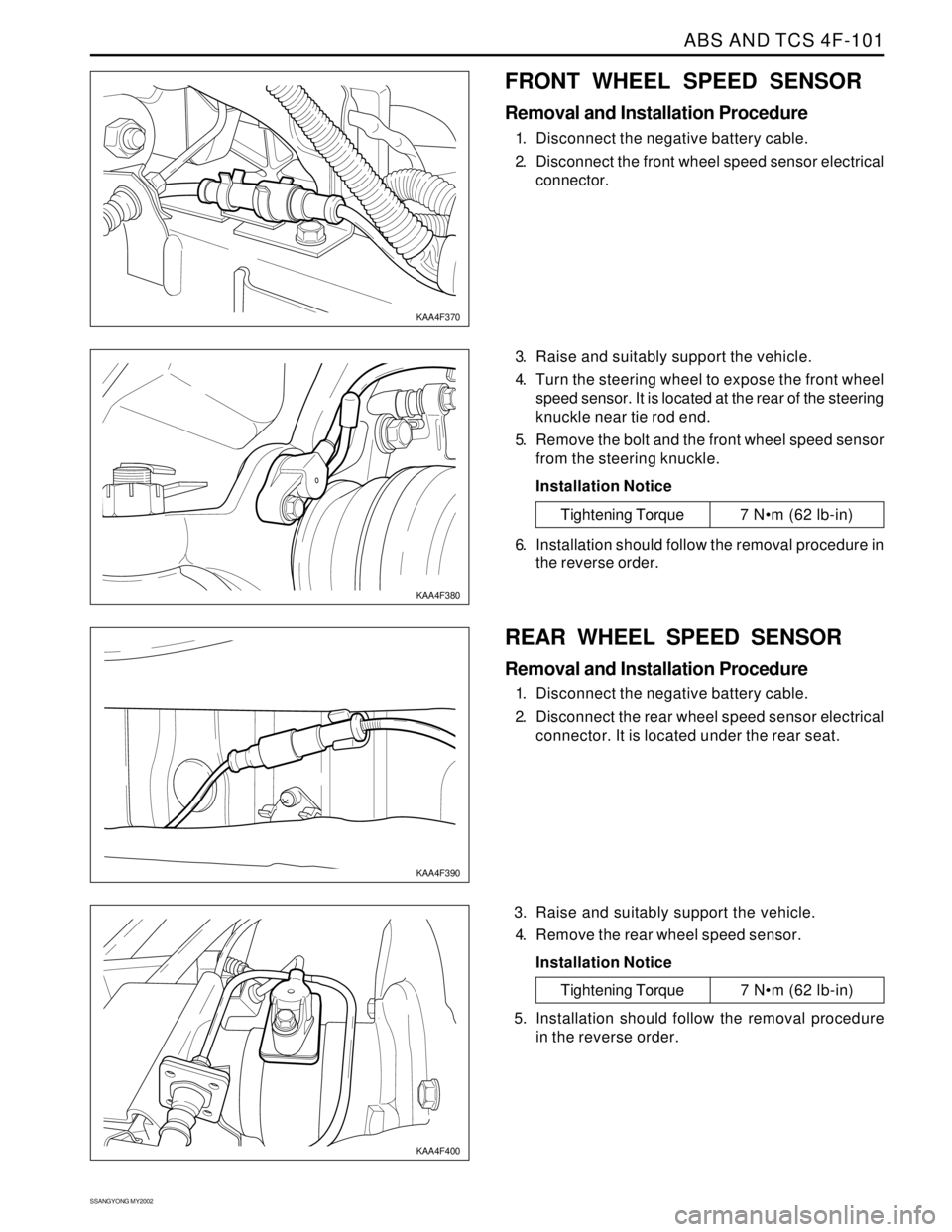
FRONT WHEEL SPEED SENSOR
Removal and Installation Procedure
1. Disconnect the negative battery cable.
2. Disconnect the front wheel speed sensor electrical
connector.
3. Raise and suitably support the vehicle.
4. Turn the steering wheel to expose the front wheel
speed sensor. It is located at the rear of the steering
knuckle near tie rod end.
5. Remove the bolt and the front wheel speed sensor
from the steering knuckle.
Installation Notice
KAA4F370
KAA4F380
Tightening Torque 7 Nm (62 lb-in)
6. Installation should follow the removal procedure in
the reverse order.
REAR WHEEL SPEED SENSOR
Removal and Installation Procedure
1. Disconnect the negative battery cable.
2. Disconnect the rear wheel speed sensor electrical
connector. It is located under the rear seat.
3. Raise and suitably support the vehicle.
4. Remove the rear wheel speed sensor.
Installation Notice
KAA4F390
KAA4F400
Tightening Torque 7 Nm (62 lb-in)
5. Installation should follow the removal procedure
in the reverse order.
Page 1097 of 2053
AUTOMATIC TRANSMISSION 5A-3
SSANGYONG MY2002
N - Neutral allows the engine to be started and oper-
ated while driving the vehicle. The inhibitor switch
allows the engine to be started. There is no power
transferred through the transmission in Neutral. But
the final drive is not locked by the parking pawl, so
thewheels are free to rotate.
D - Overdrive range is used for all normal driving
conditions. 4th gear (overdrive gear) reduces the
fuel consumption and the engine noise. Engine
braking is applied with reduced throttle.
First to second (1 → 2), first to third (1 → 3), second
to third (2 → 3), second to fourth (2 → 4), third to
fourth (3 → 4), fourth to third (4 → 3), fourth to
second (4 → 2), third to second (3 → 2), third to
first (3 → 1) and second to first (2 → 1) shifts are
all available as a function of vehicle speed, throttle
position and the time change rate of the throttle
position.
Downshifts are available for safe passing by
depress-ing the accelerator. Lockup clutch may be
enabled in 3rd and 4th gears depending on vehicle
type.
3 - Manual 3 provides three gear ratios (first through
third) and prevents the transmission from operating
in 4th gear. 3rd gear is used when driving on long
hill roads or in heavy city traffic. Downshifts are
available by depressing the accelerator.
2 - Manual 2 provides two gear ratios (first and
second). It is used to provide more power when
climbing hills or engine braking when driving down
a steep hill or starting off on slippery roads.
1 - Manual 1 is used to provide the maximum engine
braking when driving down the severe gradients.When NORMAL mode is selected upshifts will occur
to maximize fuel economy. When POWER mode is se-
lected, upshifts will occur to give maximum
performance and the POWER mode indicator light is
switched ON.
When WINTER mode is selected, starting in second
gear is facilitated, the WINTER mode indicator light is
switched ON and the POWER mode indicator light is
switched OFF.
Indicator Light
The indicator light is located on the instrument panel.
Auto shift indicator light comes ON when the ignition
switch ON and shows the gear shift control lever
position.
POWER mode indicator light comes ON when the
POWER mode is selected and when the kickdown
switch is depressed.
WINTER mode indicator light comes ON when the
WINTER mode is selected.
CONTROL SYSTEMS
BTRA M74 4WD automatic transmission consists of
two control systems. One is the electronic control
system that monitors vehicle parameters and adjusts
the transmission performance. Another is the hydraulic
control system that implements the commands of the
electronic control system commands.
ELECTRONIC CONTROL SYSTEM
The electronic control system comprises of sensors, a
TCM and seven solenoids. The TCM reads the inputs
and activates the outputs according to values stored
in Read Only Memory (ROM).
The TCM controls the hydraulic control system. This
control is via the hydraulic valve body, which contains
seven electromagnetic solenoids. Six of the seven
solenoids are used to control the line pressure, operate
the shift valves and the torque converter lock-up clutch,
and to turn ON and OFF the two regulator valves that
control the shift feel.
The seventh solenoid is the proportional or Variable
Pressure Solenoid (VPS) which works with the two regu-
lator valves to control shift feel.
Transmission Control Module (TCM)
The TCM is an in-vehicle micro-processor based trans-
mission management system. It is mounted under the
driver’s side front seat in the vehicle cabin.
The TCM contains:
Processing logic circuits which include a central mi-
croprocessor controller and a back-up memory
system.
Input circuits.
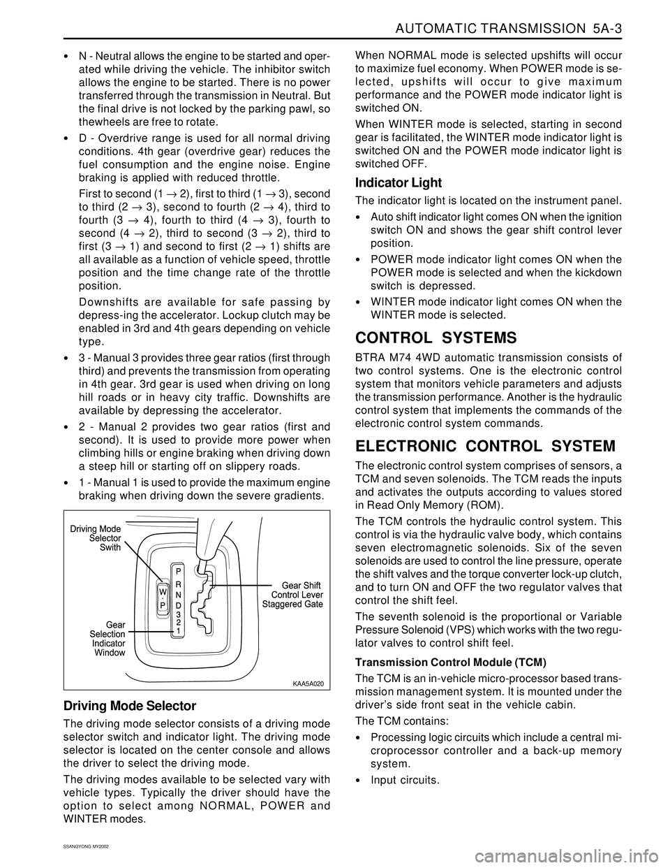
Driving Mode Selector
The driving mode selector consists of a driving mode
selector switch and indicator light. The driving mode
selector is located on the center console and allows
the driver to select the driving mode.
The driving modes available to be selected vary with
vehicle types. Typically the driver should have the
option to select among NORMAL, POWER and
WINTER modes.
KAA5A020
Page 1110 of 2053
5A-16 AUTOMATIC TRANSMISSION
SSANGYONG MY2002
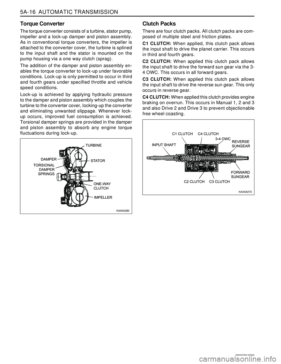
Torque Converter
The torque converter consists of a turbine, stator pump,
impeller and a lock-up damper and piston assembly.
As in conventional torque converters, the impeller is
attached to the converter cover, the turbine is splined
to the input shaft and the stator is mounted on the
pump housing via a one way clutch (sprag).
The addition of the damper and piston assembly en-
ables the torque converter to lock-up under favorable
conditions. Lock-up is only permitted to occur in third
and fourth gears under specified throttle and vehicle
speed conditions.
Lock-up is achieved by applying hydraulic pressure
to the damper and piston assembly which couples the
turbine to the converter cover, locking-up the converter
and eliminating unwanted slippage. Whenever lock-
up occurs, improved fuel consumption is achieved.
Torsional damper springs are provided in the damper
and piston assembly to absorb any engine torque
fluctuations during lock-up.
Clutch Packs
There are four clutch packs. All clutch packs are com-
posed of multiple steel and friction plates.
C1 CLUTCH: When applied, this clutch pack allows
the input shaft to drive the planet carrier. This occurs
in third and fourth gears.
C2 CLUTCH: When applied this clutch pack allows
the input shaft to drive the forward sun gear via the 3-
4 OWC. This occurs in all forward gears.
C3 CLUTCH: When applied this clutch pack allows
the input shaft to drive the reverse sun gear. This only
occurs in reverse gear.
C4 CLUTCH: When applied this clutch provides engine
braking on overrun. This occurs in Manual 1, 2 and 3
and also Drive 2 and Drive 3 to prevent objectionable
free wheel coasting.
KAA5A260
KAA5A270
Page 1330 of 2053
SSANGYONG MY2002
5B-22 MANUAL TRANSMISSION
62 - 93 Nm
(45 - 69 lb-ft)
21 - 35 Nm
(15 - 26 lb-ft)
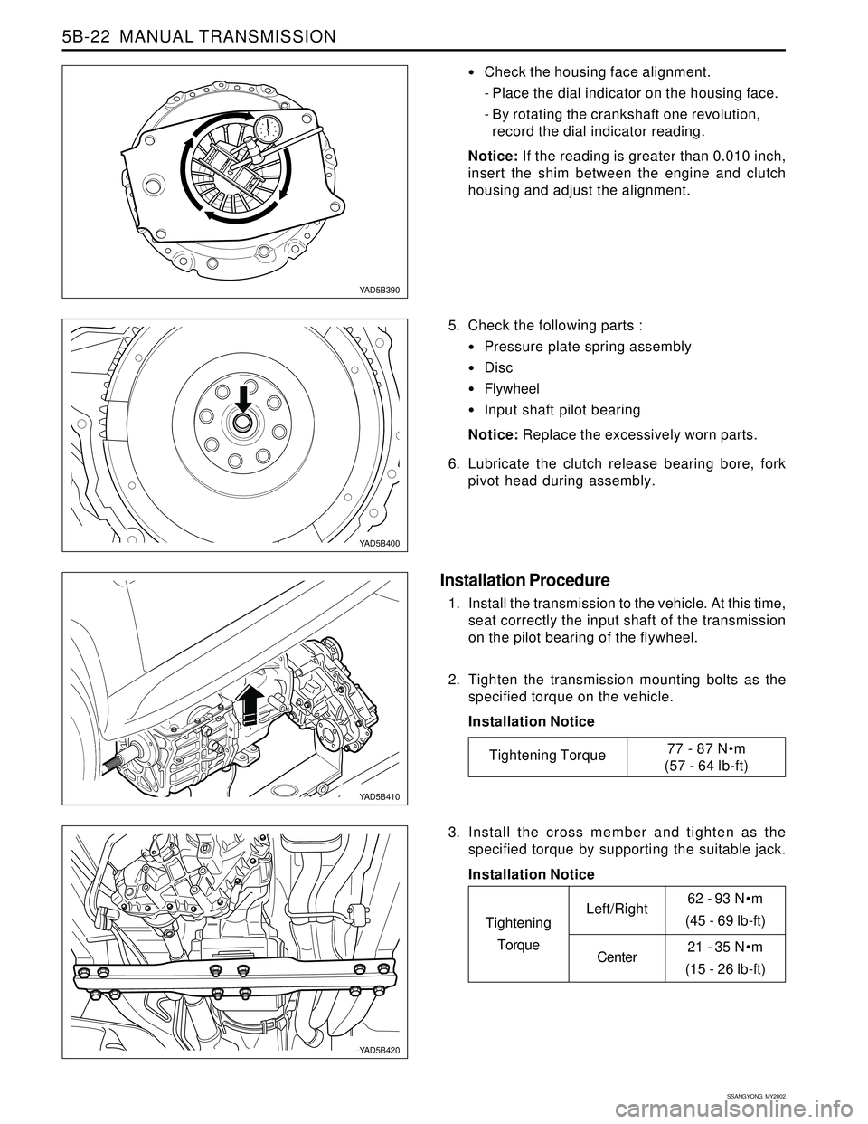
Check the housing face alignment.
- Place the dial indicator on the housing face.
- By rotating the crankshaft one revolution,
record the dial indicator reading.
Notice: If the reading is greater than 0.010 inch,
insert the shim between the engine and clutch
housing and adjust the alignment.
5. Check the following parts :
Pressure plate spring assembly
Disc
Flywheel
Input shaft pilot bearing
Notice: Replace the excessively worn parts.
6. Lubricate the clutch release bearing bore, fork
pivot head during assembly.
Installation Procedure
1. Install the transmission to the vehicle. At this time,
seat correctly the input shaft of the transmission
on the pilot bearing of the flywheel.
2. Tighten the transmission mounting bolts as the
specified torque on the vehicle.
Installation Notice
YAD5B390
YAD5B400
YAD5B410
YAD5B420
Tightening Torque77 - 87 Nm
(57 - 64 lb-ft)
3. Install the cross member and tighten as the
specified torque by supporting the suitable jack.
Installation Notice
Tightening
TorqueLeft/Right
Center
Page 1362 of 2053
CLUTCH 5C-7
SSANGYONG MY2002
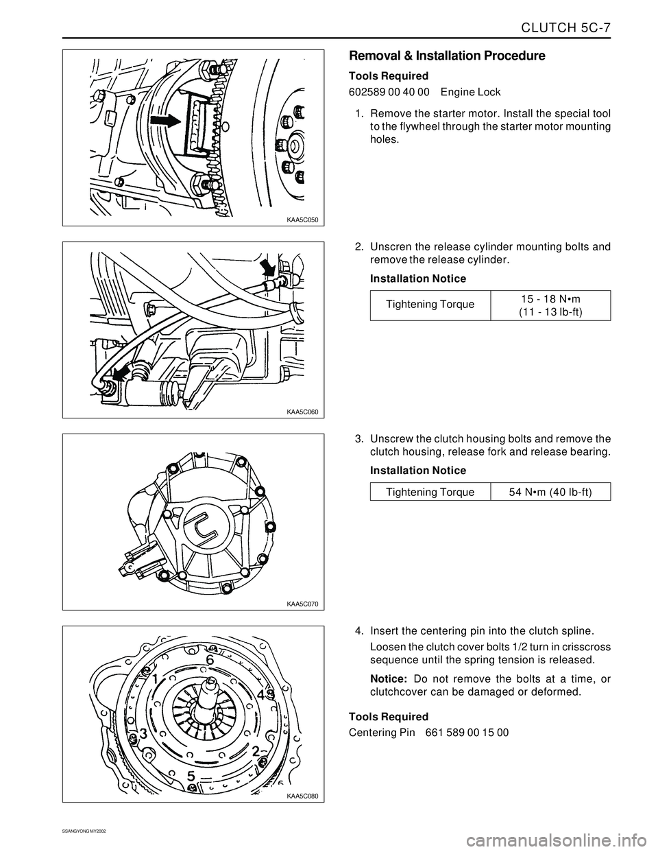
Removal & Installation Procedure
Tools Required
602589 00 40 00 Engine Lock
1. Remove the starter motor. Install the special tool
to the flywheel through the starter motor mounting
holes.
2. Unscren the release cylinder mounting bolts and
remove the release cylinder.
Installation Notice
3. Unscrew the clutch housing bolts and remove the
clutch housing, release fork and release bearing.
Installation Notice
4. Insert the centering pin into the clutch spline.
Loosen the clutch cover bolts 1/2 turn in crisscross
sequence until the spring tension is released.
Notice: Do not remove the bolts at a time, or
clutchcover can be damaged or deformed.
Tools Required
Centering Pin 661 589 00 15 00
KAA5C050
KAA5C060
KAA5C070
KAA5C080
Tightening Torque15 - 18 Nm
(11 - 13 lb-ft)
Tightening Torque 54 Nm (40 lb-ft)
Page 1363 of 2053
SSAMGYONG MY2002
5C-8 CLUTCH
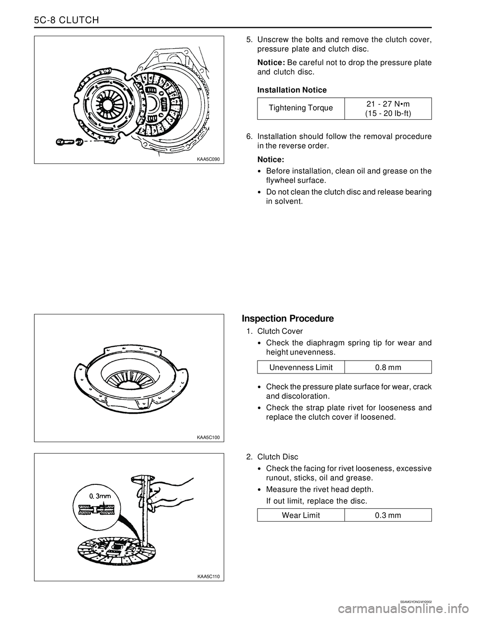
5. Unscrew the bolts and remove the clutch cover,
pressure plate and clutch disc.
Notice: Be careful not to drop the pressure plate
and clutch disc.
Installation Notice
6. Installation should follow the removal procedure
in the reverse order.
Notice:
Before installation, clean oil and grease on the
flywheel surface.
Do not clean the clutch disc and release bearing
in solvent.
2. Clutch Disc
Check the facing for rivet looseness, excessive
runout, sticks, oil and grease.
Measure the rivet head depth.
If out limit, replace the disc.
Inspection Procedure
1. Clutch Cover
Check the diaphragm spring tip for wear and
height unevenness.
Check the pressure plate surface for wear, crack
and discoloration.
Check the strap plate rivet for looseness and
replace the clutch cover if loosened.
KAA5C090
KAA5C100
KAA5C110
Tightening Torque21 - 27 Nm
(15 - 20 lb-ft)
Wear Limit 0.3 mm
Unevenness Limit 0.8 mm