1997 SSANGYONG KORANDO suspension
[x] Cancel search: suspensionPage 957 of 2053

FRONT BRAKES 4D-7
SSANGYONG MY2002
KAA4D060
KAA4D070
CALIPER ASSEMBLY
Removal and Installation Procedure
1. Raise and suitably support the vehicle.
2. Remove the front wheels. Refer to Section 2E,
Tires and Wheels.
3. Remove the brake hose mounting nut and
disconnect the hose. Plug the openings in the
caliper and the brake hose to prevent fluid loss
and contamination.
Installation Notice
Tightening Torque 30 Nm (22 lb-ft)
4. Remove the caliper mounting bolts and then
remove the caliper assembly.
Installation Notice
Tightening Torque 95 Nm (70 lb-ft)
Bleed the caliper. Refer to Section 4A, Hydraulic
Brakes.
Notice: do not move the vehicle until a firm pedal
is obtained or improper braking action will result.
Repeatedly press the brake pedal to bring the
pads in contact with the rotor.
5. Installation should follow the removal procedure
in the reverse order.
SPLASH SHIELD
Removal and Installation Procedure
1. Raise and suitably support the vehicle.
2. Remove the front wheels. Refer to Section 2E,
Tires and Wheels.
3. Remove the hub bearing assembly. Refer to
Section 2C, Front Suspension.
4. Remove the front disc brake rotor. Refer to “Front
Disc Brake Rotor” in this section.
5. Remove the splash shield bolt.
Installation Notice
KAA4D090
Tightening Torque 6 Nm (53 lb-ft)
6. Installation should follow the removal procedure
in the reverse order.
Page 989 of 2053

ABS AND TCS 4F-5
SSANGYONG MY2002
EBD (ELECTRONIC BRAKE
FORCE DISTRIBUTION) SYSTEM
System Description
As an add-on logic to the ABS base algorithm, EBD
works in a range in which the intervention thresholds
for ABS control are not reached yet.
EBD ensures that the rear wheels are sensitively
monitored for slip with respect to the front axle. If slip
is detected, the inlet valves for the rear wheels are
switched to pressure hold to prevent a further increase
in pressure at the rear-wheel breaks, thus electronically
reproducing a pressure-reduction function at the rear-
wheel brakes.
ABS features an enhanced algorithm which includes
control of the brake force distribution between the front
and rear axles. This is called Electronic Brake
Distribution. In an unloading car condition the brake
efficiency is comparable to the conventional system
but for a fully loaden vehicle the efficiency of the EBD
system is higher due to the better use of rear axle
braking capability.
The Benefits of EBD
Elimination of conventional proportioning valve EBD
utilizes the existing rear axle wheel speed sensor
to monitor rear wheel slip.
Based on many variables in algorithm a pressure
hold, increase and/or decrease pulsetrain may be
triggered at the rear wheels insuring vehicle
stability.
Vehicle approaches the ideal brake force
distribution (front to rear).
Constant brake force distribution during vehicle
lifetime.
EBD function is monitored via ABS safety logic
(conventional proportioning valves are not
monitorable).
“Keep alive” function.Service Precautions
Observe the following general precautions during any
ABS/TCS service. Failure to adhere to these
precautions may result in ABS/TCS system damage.
1. Disconnect the EBCM harness connector before
performing the electric welding procedures.
2. Carefully note the routing of the ABS/TCS wiring
and wring components during removal. The ABS/
TCS components are extremely sensitive to EMI
(eletromagnetic interference). Proper mounting is
critical during component service.
3. Disconnect the EBCM connector with the ignition
OFF.
4. Do not hang the suspension components from the
wheel speed sensor cables. The cables may be
damaged.
5. Do not use petroleum based fluids in the master
cylinder. Do not use any containers previously used
for petroleum based fluids. Petroleum causes
swelling and distortion of the rubber components
in the hydraulic brake system, resulting in water
entering the system and lowering the fluid boiling
point.
KAA4F020
Page 1780 of 2053

SSANGYONG MY2002
9K-2 SQUEAKS AND RATTLES
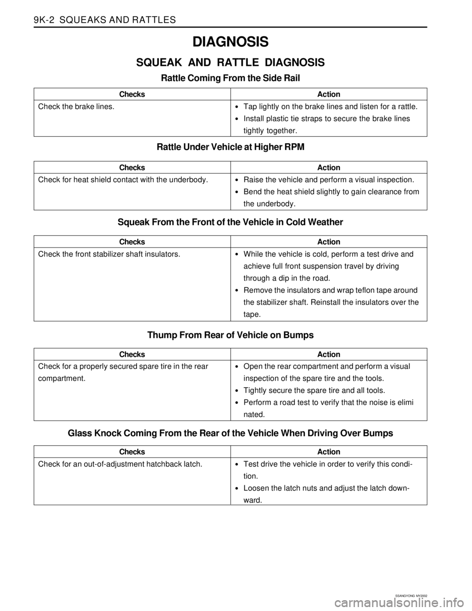
•Tap lightly on the brake lines and listen for a rattle.
Install plastic tie straps to secure the brake lines
tightly together.
Raise the vehicle and perform a visual inspection.
Bend the heat shield slightly to gain clearance from
the underbody.
While the vehicle is cold, perform a test drive and
achieve full front suspension travel by driving
through a dip in the road.
Remove the insulators and wrap teflon tape around
the stabilizer shaft. Reinstall the insulators over the
tape.
Open the rear compartment and perform a visual
inspection of the spare tire and the tools.
Tightly secure the spare tire and all tools.
Perform a road test to verify that the noise is elimi
nated.
DIAGNOSIS
SQUEAK AND RATTLE DIAGNOSIS
Rattle Coming From the Side Rail
Check the brake lines.ChecksAction
Rattle Under Vehicle at Higher RPM
Squeak From the Front of the Vehicle in Cold Weather
Check the front stabilizer shaft insulators.ChecksAction
Check for heat shield contact with the underbody.ChecksAction
Thump From Rear of Vehicle on Bumps
Check for a properly secured spare tire in the rear
compartment.ChecksAction
Glass Knock Coming From the Rear of the Vehicle When Driving Over Bumps
Check for an out-of-adjustment hatchback latch.ChecksActionTest drive the vehicle in order to verify this condi-
tion.
Loosen the latch nuts and adjust the latch down-
ward.
Page 1809 of 2053

FRAME AND UNDERBODY 9N-7
SSANGYONG MY2002
ON-VEHICLE SERVICE
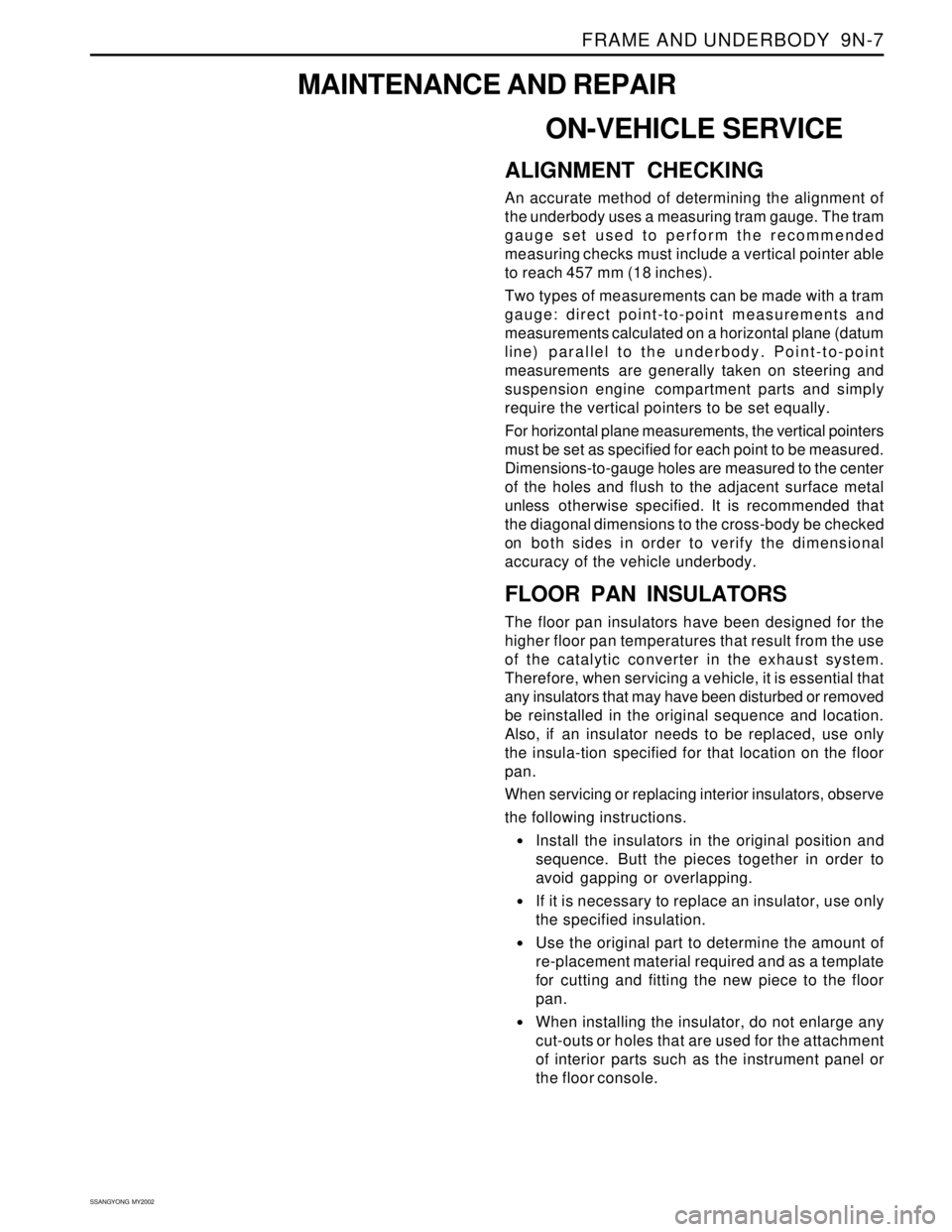
ALIGNMENT CHECKING
An accurate method of determining the alignment of
the underbody uses a measuring tram gauge. The tram
gauge set used to perform the recommended
measuring checks must include a vertical pointer able
to reach 457 mm (18 inches).
Two types of measurements can be made with a tram
gauge: direct point-to-point measurements and
measurements calculated on a horizontal plane (datum
line) parallel to the underbody. Point-to-point
measurements are generally taken on steering and
suspension engine compartment parts and simply
require the vertical pointers to be set equally.
For horizontal plane measurements, the vertical pointers
must be set as specified for each point to be measured.
Dimensions-to-gauge holes are measured to the center
of the holes and flush to the adjacent surface metal
unless otherwise specified. It is recommended that
the diagonal dimensions to the cross-body be checked
on both sides in order to verify the dimensional
accuracy of the vehicle underbody.
FLOOR PAN INSULATORS
The floor pan insulators have been designed for the
higher floor pan temperatures that result from the use
of the catalytic converter in the exhaust system.
Therefore, when servicing a vehicle, it is essential that
any insulators that may have been disturbed or removed
be reinstalled in the original sequence and location.
Also, if an insulator needs to be replaced, use only
the insula-tion specified for that location on the floor
pan.
When servicing or replacing interior insulators, observe
the following instructions.
•Install the insulators in the original position and
sequence. Butt the pieces together in order to
avoid gapping or overlapping.
If it is necessary to replace an insulator, use only
the specified insulation.
Use the original part to determine the amount of
re-placement material required and as a template
for cutting and fitting the new piece to the floor
pan.
When installing the insulator, do not enlarge any
cut-outs or holes that are used for the attachment
of interior parts such as the instrument panel or
the floor console.
MAINTENANCE AND REPAIR
Page 1811 of 2053

FRAME AND UNDERBODY 9N-9
SSANGYONG MY2002
GENERAL DESCRIPTION AND SYSTEM OPERATION
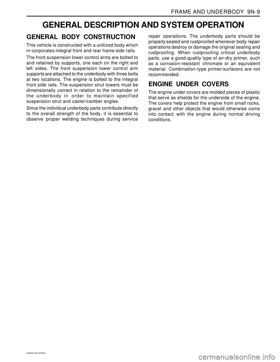
GENERAL BODY CONSTRUCTION
This vehicle is constructed with a unitized body which
in-corporates integral front and rear frame side rails.
The front suspension lower control arms are bolted to
and retained by supports, one each on the right and
left sides. The front suspension lower control arm
supports are attached to the underbody with three bolts
at two locations. The engine is bolted to the integral
front side rails. The suspension strut towers must be
dimensionally correct in relation to the remainder of
the underbody in order to maintain specified
suspension strut and caster/camber angles.
Since the individual underbody parts contribute directly
to the overall strength of the body, it is essential to
observe proper welding techniques during servicerepair operations. The underbody parts should be
properly sealed and rustproofed whenever body repair
operations destroy or damage the original sealing and
rustproofing. When rustproofing critical underbody
parts, use a good-quality type of air-dry primer, such
as a corrosion-resistant chromate or an equivalent
material. Combination-type primer/surfacers are not
recommended.
ENGINE UNDER COVERS
The engine under covers are molded pieces of plastic
that serve as shields for the underside of the engine.
The covers help protect the engine from small rocks,
gravel and other objects that would otherwise come
into contact with the engine during normal driving
conditions.