Page 1256 of 2053
AUTOMATIC TRANSMISSION 5A-161
SSANGYONG MY2002
DISASSEMBLY PROCEDURE
Transmission
Tools Required
0555-336256Transmission Bench Cradle
0555-336257Pump Puller
Notice:
Remove the inhibitor switch before washing the
transmission in solvent or hot wash.
It is assumed that the transmission fluid has been
drained when the transmission was removed from
the vehicle and that the ‘special tools’ quoted are
available.
The transmission is dismantled in a modular fashion,
and the details of disassembly for each module are
given under the appropriate subject. Refer to Special
Tools Table in this chapter for details of all special
tools required when performing disassembly
procedures.
Technicians overhauling these transmissions will
also require a selection of good quality Torx bit
sockets, in particular numbers 30, 40 and 50, and
an 8 mm, 10 mm and 12 mm double hex socket.
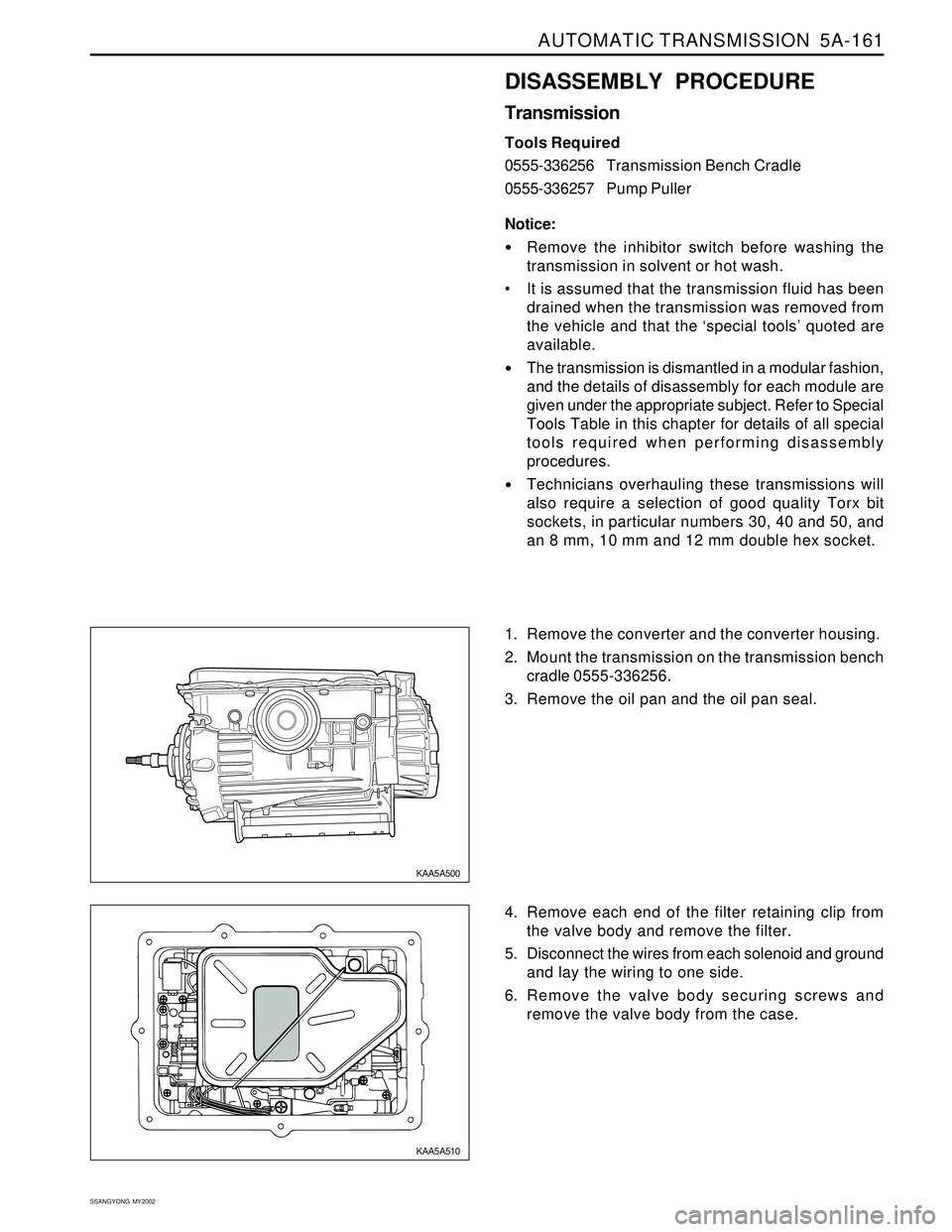
1. Remove the converter and the converter housing.
2. Mount the transmission on the transmission bench
cradle 0555-336256.
3. Remove the oil pan and the oil pan seal.
4. Remove each end of the filter retaining clip from
the valve body and remove the filter.
5. Disconnect the wires from each solenoid and ground
and lay the wiring to one side.
6. Remove the valve body securing screws and
remove the valve body from the case.
KAA5A500
KAA5A510
Page 1269 of 2053
5A-174 AUTOMATIC TRANSMISSION
SSANGYONG MY2002
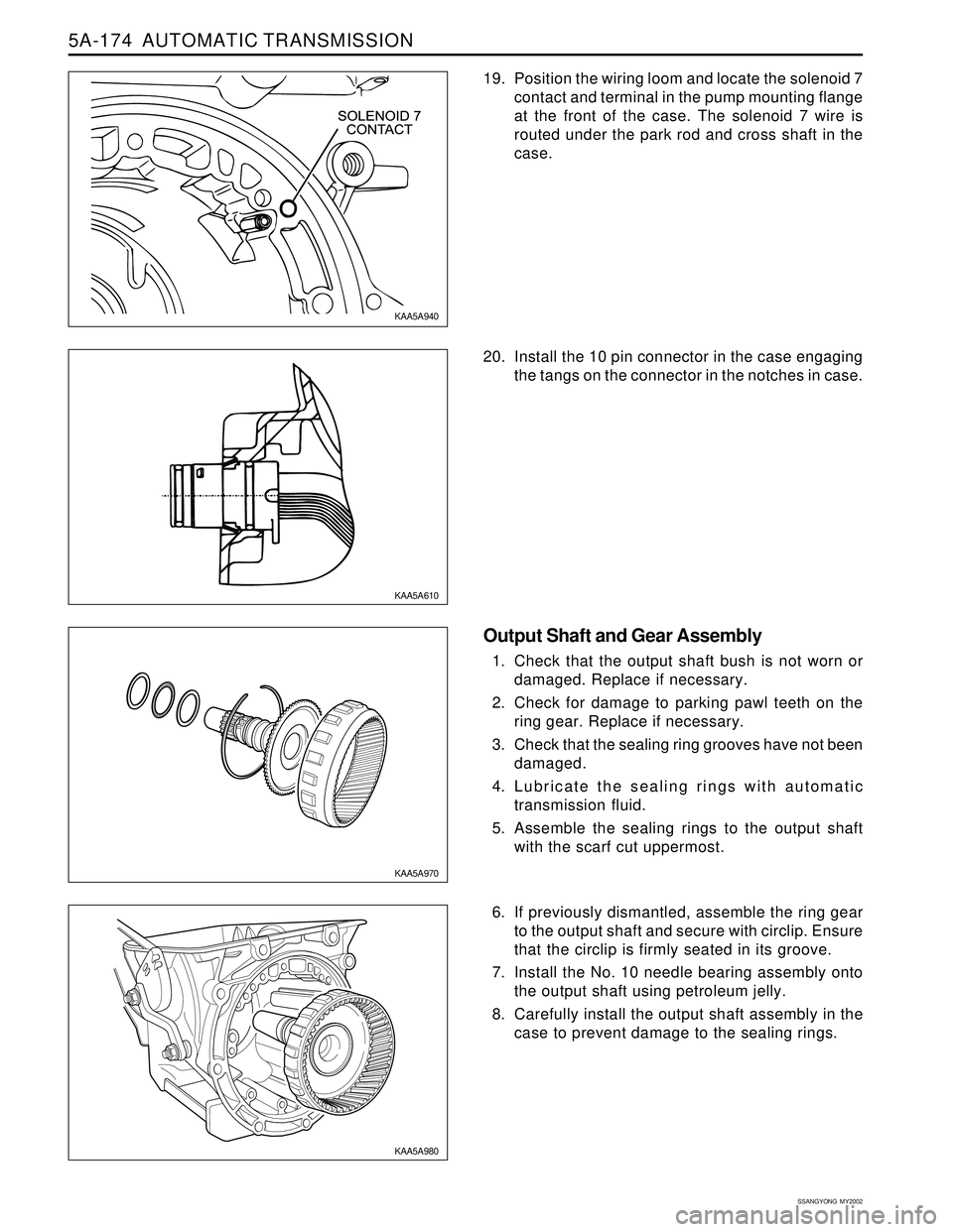
19. Position the wiring loom and locate the solenoid 7
contact and terminal in the pump mounting flange
at the front of the case. The solenoid 7 wire is
routed under the park rod and cross shaft in the
case.
20. Install the 10 pin connector in the case engaging
the tangs on the connector in the notches in case.
Output Shaft and Gear Assembly
1. Check that the output shaft bush is not worn or
damaged. Replace if necessary.
2. Check for damage to parking pawl teeth on the
ring gear. Replace if necessary.
3. Check that the sealing ring grooves have not been
damaged.
4. Lubricate the sealing rings with automatic
transmission fluid.
5. Assemble the sealing rings to the output shaft
with the scarf cut uppermost.
6. If previously dismantled, assemble the ring gear
to the output shaft and secure with circlip. Ensure
that the circlip is firmly seated in its groove.
7. Install the No. 10 needle bearing assembly onto
the output shaft using petroleum jelly.
8. Carefully install the output shaft assembly in the
case to prevent damage to the sealing rings.
KAA5A940
KAA5A610
KAA5A970
KAA5A980
Page 1270 of 2053
AUTOMATIC TRANSMISSION 5A-175
SSANGYONG MY2002
Rear Band Assembly
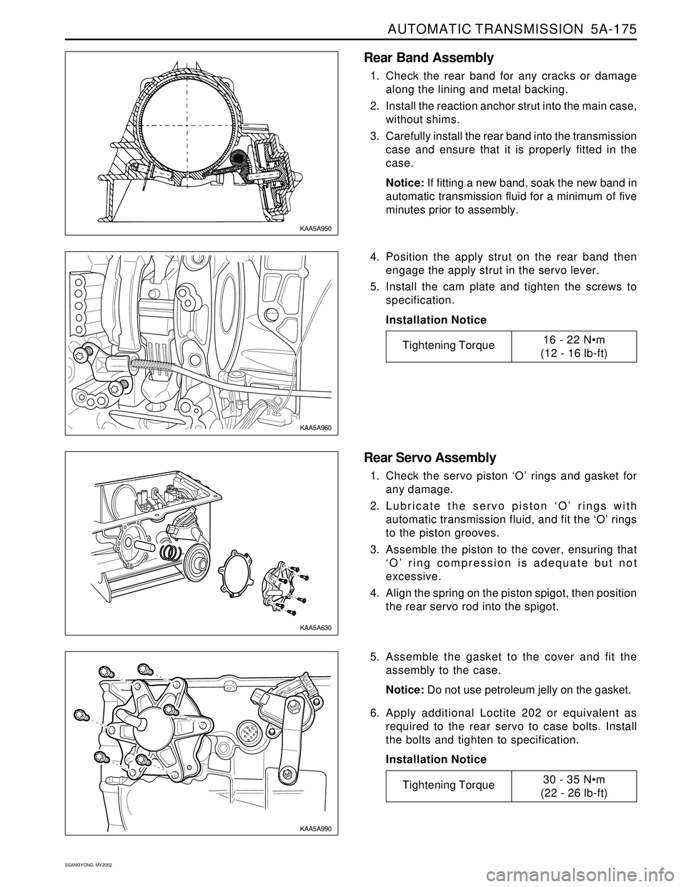
1. Check the rear band for any cracks or damage
along the lining and metal backing.
2. Install the reaction anchor strut into the main case,
without shims.
3. Carefully install the rear band into the transmission
case and ensure that it is properly fitted in the
case.
Notice: If fitting a new band, soak the new band in
automatic transmission fluid for a minimum of five
minutes prior to assembly.
4. Position the apply strut on the rear band then
engage the apply strut in the servo lever.
5. Install the cam plate and tighten the screws to
specification.
Installation Notice
Rear Servo Assembly
1. Check the servo piston ‘O’ rings and gasket for
any damage.
2. Lubricate the servo piston ‘O’ rings with
automatic transmission fluid, and fit the ‘O’ rings
to the piston grooves.
3. Assemble the piston to the cover, ensuring that
‘O’ ring compression is adequate but not
excessive.
4. Align the spring on the piston spigot, then position
the rear servo rod into the spigot.
5. Assemble the gasket to the cover and fit the
assembly to the case.
Notice: Do not use petroleum jelly on the gasket.
6. Apply additional Loctite 202 or equivalent as
required to the rear servo to case bolts. Install
the bolts and tighten to specification.
Installation Notice
KAA5A950
KAA5A960
KAA5A630
KAA5A990
Tightening Torque30 - 35 Nm
(22 - 26 lb-ft)
Tightening Torque16 - 22 Nm
(12 - 16 lb-ft)
Page 1271 of 2053
5A-176 AUTOMATIC TRANSMISSION
SSANGYONG MY2002
Planet Carrier Assembly and Centre Support
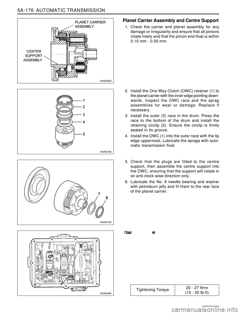
1. Check the carrier and planet assembly for any
damage or irregularity and ensure that all pinions
rotate freely and that the pinion end float is within
0.10 mm - 0.50 mm.
2. Install the One Way Clutch (OWC) retainer (1) to
the planet carrier with the inner edge pointing down-
wards. Inspect the OWC race and the sprag
assemblies for wear or damage. Replace if
necessary.
3. Install the outer (3) race in the drum. Press the
race to the bottom of the drum and install the
retaining circlip (2). Ensure the circlip is firmly
seated in its groove.
4. Install the OWC (1) into the outer race with the lip
edge uppermost. Lubricate the sprags with auto-
matic transmission fluid.
5. Check that the plugs are fitted to the centre
support, then assemble the centre support into
the OWC, ensuring that the support will rotate in
an anti-clock-wise direction only.
6. Lubricate the No. 9 needle bearing and washer
with petroleum jelly and fit them to the rear face
of the planet carrier.
7. In s t a l l th e
KAA5A0A0
KAA5A760
KAA5A750
KAA5A560
Tightening Torque20 - 27 Nm
(15 - 20 lb-ft)
Page 1272 of 2053
AUTOMATIC TRANSMISSION 5A-177
SSANGYONG MY2002
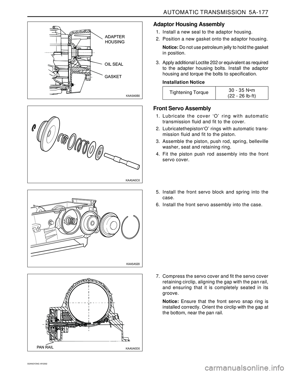
Adaptor Housing Assembly
1. Install a new seal to the adaptor housing.
2. Position a new gasket onto the adaptor housing.
Notice: Do not use petroleum jelly to hold the gasket
in position.
3. Apply additional Loctite 202 or equivalent as required
to the adapter housing bolts. Install the adaptor
housing and torque the bolts to specification.
Installation Notice
Front Servo Assembly
1. Lubricate the cover ‘O’ ring with automatic
transmission fluid and fit to the cover.
2. Lubricatethepiston‘O’ rings with automatic trans-
mission fluid and fit to the piston.
3. Assemble the piston, push rod, spring, belleville
washer, seat and retaining ring.
4. Fit the piston push rod assembly into the front
servo cover.
5. Install the front servo block and spring into the
case.
6. Install the front servo assembly into the case.
KAA5A0C0
KAA5A520 KAA5A0B0
Tightening Torque30 - 35 Nm
(22 - 26 lb-ft)
7. Compress the servo cover and fit the servo cover
retaining circlip, aligning the gap with the pan rail,
and ensuring that it is completely seated in its
groove.
Notice: Ensure that the front servo snap ring is
installed correctly. Orient the circlip with the gap at
the bottom, near the pan rail.
KAA5A0D0
Page 1273 of 2053
5A-178 AUTOMATIC TRANSMISSION
SSANGYONG MY2002
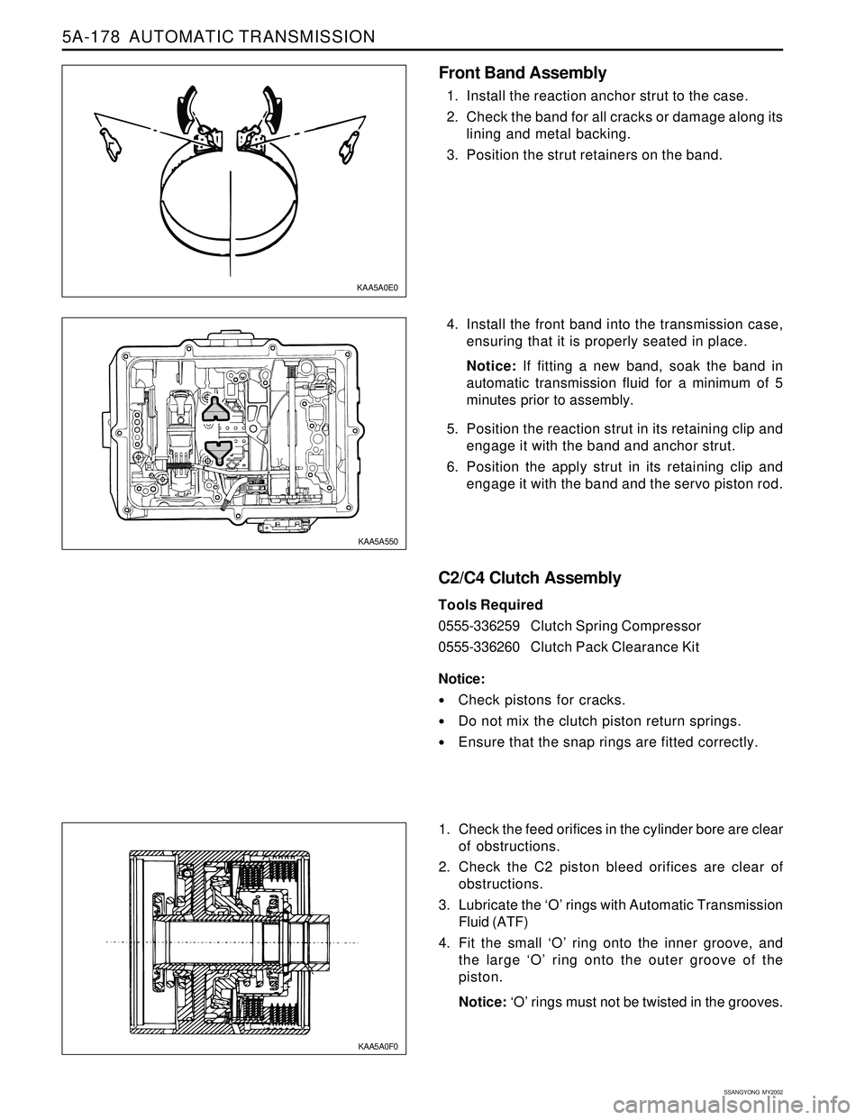
4. Install the front band into the transmission case,
ensuring that it is properly seated in place.
Notice: If fitting a new band, soak the band in
automatic transmission fluid for a minimum of 5
minutes prior to assembly.
5. Position the reaction strut in its retaining clip and
engage it with the band and anchor strut.
6. Position the apply strut in its retaining clip and
engage it with the band and the servo piston rod.
C2/C4 Clutch Assembly
Tools Required
0555-336259Clutch Spring Compressor
0555-336260Clutch Pack Clearance Kit
Notice:
Check pistons for cracks.
Do not mix the clutch piston return springs.
Ensure that the snap rings are fitted correctly.
1. Check the feed orifices in the cylinder bore are clear
of obstructions.
2. Check the C2 piston bleed orifices are clear of
obstructions.
3. Lubricate the ‘O’ rings with Automatic Transmission
Fluid (ATF)
4. Fit the small ‘O’ ring onto the inner groove, and
the large ‘O’ ring onto the outer groove of the
piston.
Notice: ‘O’ rings must not be twisted in the grooves.
KAA5A0E0
KAA5A550
KAA5A0F0
Front Band Assembly
1. Install the reaction anchor strut to the case.
2. Check the band for all cracks or damage along its
lining and metal backing.
3. Position the strut retainers on the band.
Page 1278 of 2053
AUTOMATIC TRANSMISSION 5A-183
SSANGYONG MY2002
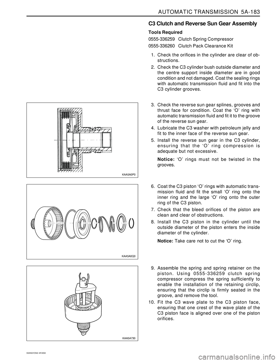
C3 Clutch and Reverse Sun Gear Assembly
Tools Required
0555-336259Clutch Spring Compressor
0555-336260Clutch Pack Clearance Kit
1. Check the orifices in the cylinder are clear of ob-
structions.
2. Check the C3 cylinder bush outside diameter and
the centre support inside diameter are in good
condition and not damaged. Coat the sealing rings
with automatic transmission fluid and fit into the
C3 cylinder grooves.
3. Check the reverse sun gear splines, grooves and
thrust face for condition. Coat the ‘O’ ring with
automatic transmission fluid and fit it to the groove
of the reverse sun gear.
4. Lubricate the C3 washer with petroleum jelly and
fit to the inner face of the reverse sun gear.
5. Install the reverse sun gear in the C3 cylinder,
ensuring that the ‘O’ ring compression is
adequate but not excessive.
Notice: ‘O’ rings must not be twisted in the
grooves.
KAA5A0P0
6. Coat the C3 piston ‘O’ rings with automatic trans-
mission fluid and fit the small ‘O’ ring onto the
inner ring and the large ‘O’ ring onto the outer
ring of the C3 piston.
7. Check that the bleed orifices of the piston are
clean and clear of obstructions.
8. Install the C3 piston in the cylinder until the
outside diameter of the piston enters the inside
diameter of the cylinder.
Notice: Take care not to cut the ‘O’ ring.
9. Assemble the spring and spring retainer on the
piston. Using 0555-336259 clutch spring
compressor compress the spring sufficiently to
enable the installation of the retaining circlip,
ensuring that the circlip is firmly seated in the
groove, and remove the tool.
10. Fit the C3 wave plate to the C3 piston face,
ensuring that one crest of the wave plate of the
C3 piston face is aligned over one of the piston
orifices.
KAA5A0Q0
KAA5A730
Page 1280 of 2053
AUTOMATIC TRANSMISSION 5A-185
SSANGYONG MY2002
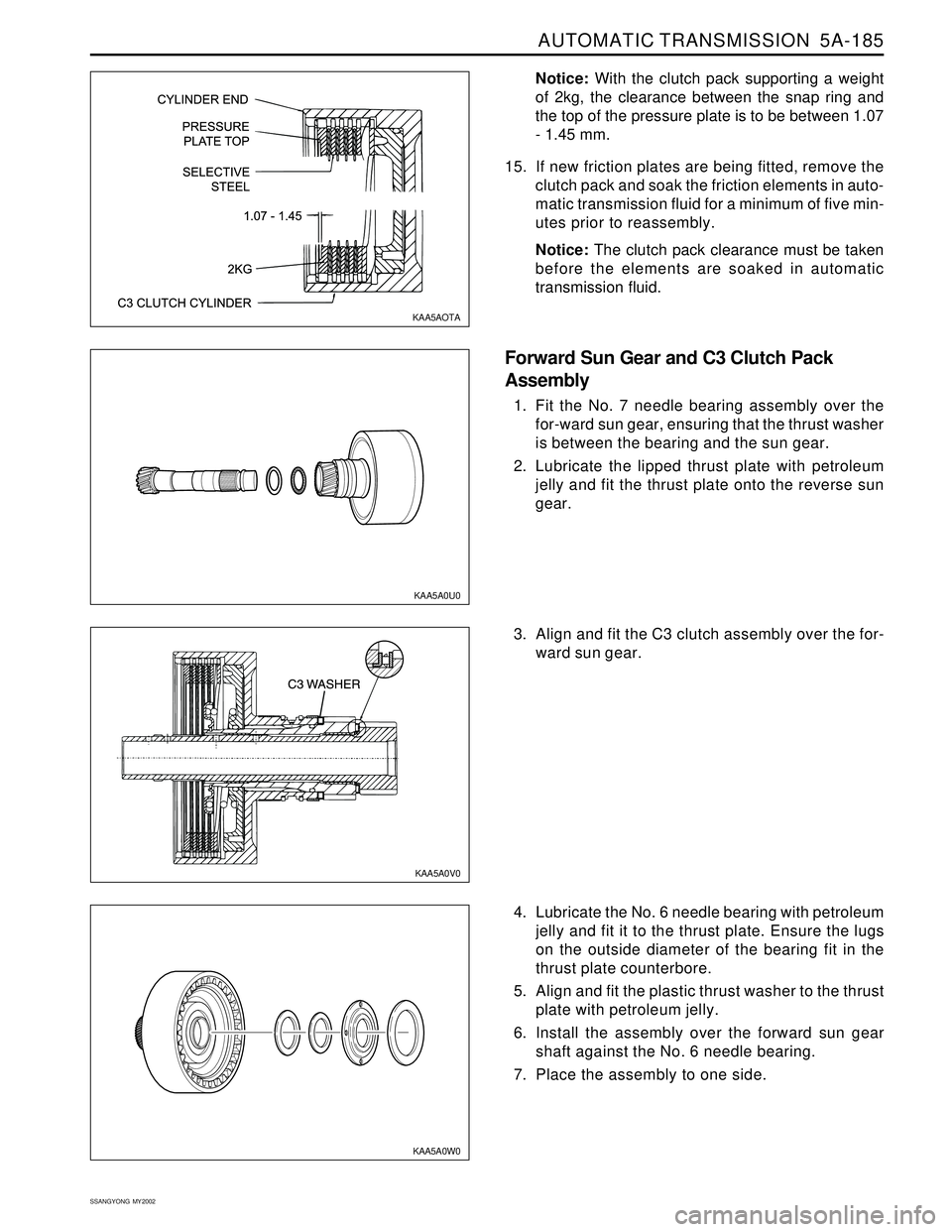
Notice: With the clutch pack supporting a weight
of 2kg, the clearance between the snap ring and
the top of the pressure plate is to be between 1.07
- 1.45 mm.
15. If new friction plates are being fitted, remove the
clutch pack and soak the friction elements in auto-
matic transmission fluid for a minimum of five min-
utes prior to reassembly.
Notice: The clutch pack clearance must be taken
before the elements are soaked in automatic
transmission fluid.
Forward Sun Gear and C3 Clutch Pack
Assembly
1. Fit the No. 7 needle bearing assembly over the
for-ward sun gear, ensuring that the thrust washer
is between the bearing and the sun gear.
2. Lubricate the lipped thrust plate with petroleum
jelly and fit the thrust plate onto the reverse sun
gear.
KAA5A0U0 KAA5AOTA
3. Align and fit the C3 clutch assembly over the for-
ward sun gear.
4. Lubricate the No. 6 needle bearing with petroleum
jelly and fit it to the thrust plate. Ensure the lugs
on the outside diameter of the bearing fit in the
thrust plate counterbore.
5. Align and fit the plastic thrust washer to the thrust
plate with petroleum jelly.
6. Install the assembly over the forward sun gear
shaft against the No. 6 needle bearing.
7. Place the assembly to one side.
KAA5A0W0KAA5A0V0