1997 SSANGYONG KORANDO automatic transmission fluid
[x] Cancel search: automatic transmission fluidPage 545 of 2053

1A3 -- 10 GENERAL ENGINE INFORMATION
D AEW OO M Y_2000
DIAGNOSIS
OIL LEAK DIAGNOSIS
Most fluid oil leaks are easily located and repaired by
visually finding the leak and replacing or repairing the
necessary parts. On some occasions a fluid leak may be
difficult to locate or repair. The following procedures may
help you in locating and repairing most leaks.
Finding the Leak
1. Identify the fluid. Determine whether it is engine oil,
automatic transmission fluid, power steering fluid,
etc.
2. Identify where the fluid is leaking from.
2.1 After running the vehicle at normal operating
temperature, park the vehicle over a large sheet
of paper.
2.2 Wait a few minutes.
2.3 You should be able to find the approximate loca-
tion of the leak by the drippings on the paper.
3. Visually check around the suspected component.
Check around all the gasket mating surfaces for
leaks. A mirror is useful for finding leaks in areas that
are hard to reach.
4. If the leak still cannot be found, it may be necessary
to clean the suspected area with a degreaser, steam
or spray solvent.
4.1 Clean the area well.
4.2 Dry the area.
4.3 Operate the vehicle for several miles at normal
operating temperature and varying speeds.
4.4 After operating the vehicle, visually check the
suspected component.
4.5 If you still cannot locate the leak, try using the
powder or black light and dye method.
Powder Method
1. Clean the suspected area.
2. Apply an aerosol-- type powder (such as foot powder)
to the suspected area.
3. Operate the vehicle under normal operating condi-
tions.
4. Visually inspect the suspected component. You
should be able to trace the leak path over the white
powder surface to the source.
Black Light and Dye Method
A dye and light kit is available for finding leaks, Refer to
the manufacturer ’s directions when using the kit.
1. Pour the specified amount of dye into the engine oil fill
tube.
2. Operate the vehicle normal operating conditions as
directed in the kit.
3. Direct the light toward the suspected area. The dyed
fluid willappear as a yellow path leading to the
source.
Repairing the Leak
Once the origin of the leak has been pinpointed and
traced back to its source, the cause of the leak must be
determined n order for it to be repaired properly. If a gas-
ket is replaced, but the sealing flange is bent, the new
gasket will not repair the leak. Thebent flange must be
repaired also. Before attempting to repair a leak, check
for the following conditions and correct them as they
may cause a leak.
Gaskets
DThe fluid level/pressure is too high.
DThe crankcase ventilation system is malfunctioning.
DThe fasteners are tightened improperly or the threads
are dirty or damaged.
DThe flanges or the sealing surface is warped.
DThere are scratches, burrs or other damage to the
sealing surface.
DThe gasket is damaged or worn.
DThere is cracking or porosity of the component.
DAn improper seal was used (where applicable).
Seals
DThe fluid level/pressure is too high.
DThe crankcase ventilation system is malfunctioning.
DThe seal bore is damaged (scratched, burred or
nicked).
DThe seal is damaged or worn.
DImproper installation is evident.
DThere are cracks in the components.
DThe shaft surface is scratched, nicked or damaged.
DA loose or worn bearing is causing excess seal wear.
Page 565 of 2053

1B3 -- 16 OM600 ENGINE MECHANICAL
D AEW OO M Y_2000
16. Remove the power steering pump lines.
Notice
Completely drain the fluid.
17. Disconnect the fuel feed line with prefilter from the
feed pump on injection pump.
18. Vehicle with automatic transmission.
Remove the hydraulic lines (19, 20) from oil cooler
(2).
19. Disconnect the engine harness.
20. Disconnect the preheating time relay cable.
Page 1095 of 2053
SECTION 5A
AUTOMATIC TRANSMISSION
CAUTION: Disconnect the negative battery cable before removing or installing any electrical unit or when a
tool or equipment could easily come in contact with exposed electrical terminals. Disconnecting this cable
will help prevent personal injury and damage to the vehicle. The ignition must also be in LOCK unless
otherwise noted.
TABLE OF CONTENTS
Description and Operation . . . . . . . . . . . . . . . . . 5A-2
BTRA M74 4WD Automatic Transmission . . . . . . 5A-2
Operators Interfaces . . . . . . . . . . . . . . . . . . . . . 5A-2
Control Systems . . . . . . . . . . . . . . . . . . . . . . . . 5A-3
Electronic Control System . . . . . . . . . . . . . . . . . 5A-3
Hydraulic Control System . . . . . . . . . . . . . . . . . . 5A-9
Hydraulic Control Circuit . . . . . . . . . . . . . . . . . . 5A-10
Power Train System . . . . . . . . . . . . . . . . . . . . . 5A-14
Power Flows . . . . . . . . . . . . . . . . . . . . . . . . . . 5A-18
Park and Neutral . . . . . . . . . . . . . . . . . . . . . . . 5A-20
Reverse . . . . . . . . . . . . . . . . . . . . . . . . . . . . . . 5A-22
Manual 1 . . . . . . . . . . . . . . . . . . . . . . . . . . . . . 5A-24
Drive 1 . . . . . . . . . . . . . . . . . . . . . . . . . . . . . . 5A-26
Drive 2 and Manual 2 . . . . . . . . . . . . . . . . . . . . 5A-28
Drive 3 and Manual 3 . . . . . . . . . . . . . . . . . . . . 5A-30
Drive 3 Lock Up and Manual 3 Lock Up . . . . . . 5A-32
Drive 4 (Overdrive) . . . . . . . . . . . . . . . . . . . . . 5A-34
Drive 4 Lock Up . . . . . . . . . . . . . . . . . . . . . . . . 5A-36
Diagnostic Information and Procedures . . . . . 5A-38
Diagnosis . . . . . . . . . . . . . . . . . . . . . . . . . . . . . 5A-38
Basic Knowledge Required . . . . . . . . . . . . . . . 5A-38
Functional Check Procedure . . . . . . . . . . . . . . . 5A-38
Transmission Fluid Level Service Procedure . . . 5A-38
Fluid Leak Diagnosis and Repair . . . . . . . . . . . 5A-39
Electrical / Garage Shift Test . . . . . . . . . . . . . . 5A-40
Road Test Procedure . . . . . . . . . . . . . . . . . . . . 5A-40
Electronic Adjustments . . . . . . . . . . . . . . . . . . 5A-40
Symptom Diagnosis . . . . . . . . . . . . . . . . . . . . . 5A-41
Drive Faults . . . . . . . . . . . . . . . . . . . . . . . . . . . 5A-41
Faulty Shift Pattern . . . . . . . . . . . . . . . . . . . . . . 5A-42Shift Quality Faults . . . . . . . . . . . . . . . . . . . . . . 5A-44
After Teardown Faults . . . . . . . . . . . . . . . . . . . 5A-46
Trouble Code Diagnosis - Gasoline Vehicle . . 5A-48
TCM Diagnostic System Overview . . . . . . . . . . 5A-48
Clearing Trouble Codes . . . . . . . . . . . . . . . . . . 5A-48
Diagnostic Trouble Codes . . . . . . . . . . . . . . . . 5A-48
Trouble Code Diagnosis - Diesel Vehicle . . . . . 5A-50
TCM Diagnostic System Overview . . . . . . . . . . 5A-50
Clearing Trouble Codes . . . . . . . . . . . . . . . . . . 5A-50
Diagnostic Trouble Codes . . . . . . . . . . . . . . . . 5A-50
Repair Instructions . . . . . . . . . . . . . . . . . . . . . . 5A-157
On-Vehicle Service . . . . . . . . . . . . . . . . . . . . . . . 5A-157
Transmission . . . . . . . . . . . . . . . . . . . . . . . . . . 5A-157
Unit Repair . . . . . . . . . . . . . . . . . . . . . . . . . . . . 5A-160
Rebuild Warnings . . . . . . . . . . . . . . . . . . . . . . 5A-160
Disassembly Procedure . . . . . . . . . . . . . . . . . . 5A-161
Assembly Procedure . . . . . . . . . . . . . . . . . . . . 5A-171
Front and Rear Band Adjustment . . . . . . . . . . . 5A-199
Gear Shift Control Lever . . . . . . . . . . . . . . . . . . 5A-202
Kickdown Switch . . . . . . . . . . . . . . . . . . . . . . . 5A-202
Specifications . . . . . . . . . . . . . . . . . . . . . . . . . . 5A-203
General Specification . . . . . . . . . . . . . . . . . . . . 5A-203
Fastener Tightening Specifications . . . . . . . . . . 5A-205
Schematic and Routing Diagrams . . . . . . . . . . 5A-206
TCM Wiring Diagrams (Gasoline Engine) . . . . . 5A-206
TCM Wiring Diagrams (Diesel Engine) . . . . . . . 5A-208
Connector End View . . . . . . . . . . . . . . . . . . . . . 5A-210
Special Tools and Equipment . . . . . . . . . . . . . 5A-211
Special Tools Table . . . . . . . . . . . . . . . . . . . . . 5A-211
Page 1096 of 2053
5A-2 AUTOMATIC TRANSMISSION
SSANGYONG MY2002
OPERATORS INTERFACES
There are three operator interfaces as the following;
•Gear Shift Control Lever
Driving Mode Selector
Indicator Light
Gear Shift Control lever
The transmission uses a conventional shift control lever.
The gear shift control lever can be moved from one
position to another within the staggered configuration
of the shift control lever gate to positively indicate the
gear selection.
DESCRIPTION AND OPERATION
BTRA M74 4WD AUTOMATIC
TRANSMISSION
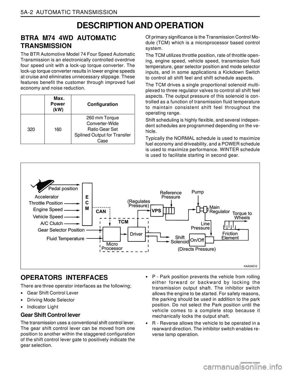
The BTR Automotive Model 74 Four Speed Automatic
Transmission is an electronically controlled overdrive
four speed unit with a lock-up torque converter. The
lock-up torque converter results in lower engine speeds
at cruise and eliminates unnecessary slippage. These
features benefit the customer through improved fuel
economy and noise reduction.Of primary significance is the Transmission Control Mo-
dule (TCM) which is a microprocessor based control
system.
The TCM utilizes throttle position, rate of throttle open-
ing, engine speed, vehicle speed, transmission fluid
temperature, gear selector position and mode selector
inputs, and in some applications a Kickdown Switch
to control all shift feel and shift schedule aspects.
The TCM drives a single proportional solenoid multi-
plexed to three regulator valves to control all shift feel
aspects. The output pressure of this solenoid is con-
trolled as a function of transmission fluid temperature
to maintain consistent shift feel throughout the
operating range.
Shift scheduling is highly flexible, and several indepen-
dent schedules are programmed depending on the ve-
hicle.
Typically the NORMAL schedule is used to maximize
fuel economy and driveability, and a POWER schedule
is used to maximize performance. WINTER schedule
is used to facilitate starting in second gear. Configuration Max.
Power
(kW)
320 160260 mm Torque
Converter-Wide
Ratio Gear Set
Splined Output for Transfer
Case
P - Park position prevents the vehicle from rolling
either forward or backward by locking the
transmission output shaft. The inhibitor switch
allows the engine to be started. For safety reasons,
the parking should be used in addition to the park
position. Do not select the Park position until the
vehicle comes to a complete stop because it
mechanically locks the output shaft.
R - Reverse allows the vehicle to be operated in a
rearward direction. The inhibitor switch enables re-
verse lamp operation.
KAA5A010
Page 1098 of 2053

5A-4 AUTOMATIC TRANSMISSION
SSANGYONG MY2002
Output circuits which control external devices such
as the Variable Pressure Solenoid (VPS) driver, On/
Off solenoid drivers, a diagnostics output and the
driving mode indicator light.
Processing Logic
Shift schedule and calibration information is stored in
an Erasable Programmable Read Only Memory (EPROM).
Throttle input calibration constants and the diagnostics
information are stored in Electrically Erasable Program-
mable Read Only Memory (EEPROM) that retains the
memory even when power to the TCM is disconnected.
TCM continuously monitors the input values and uses
these, via the shift schedule, to determine the required
gear state. At the same time it monitors, via the solenoid
outputs, the current gear state, whenever the input
conditions change such that the required gear state is
different to the current gear state, the TCM initiates a
gear shift to bring the two states back into line.
Once the TCM has determined the type of gearshift
required the TCM accesses the shift logic, estimates
the engine torque output, adjusts the variable pressure
solenoid ramp pressure then executes the shift.The TCM continuously monitors every input and output
circuit for short or open circuits and operating range.
When a failure or abnormal operation is detected the
TCM records the condition code in the diagnostics
memory and implements a Limp Home Mode (LHM).
The actual limp home mode used depends upon the
failure detected with the object to maintain maximum
drive-ability without damaging the transmission. In
general input failures are handled by providing a default
value. Output failures, which are capable of damaging
the transmission, result in full limp mode giving only
third or fourth gear and reverse. For further details of
limp modes and memory retention refer to the
Diagnostic Trouble Code Diagnosis Section.
The TCM is designed to operate at ambient
temperatures between - 40 and 85 °C (- 40 and 185 °F).
It is also protected against electrical noise and voltage
spikes, however all the usual precautions should be
observed, for example when arc welding or jump
starting.
TCM Inputs
To function correctly, the TCM requires engine speed,
vehicle speed, transmission fluid temperature, throttle
position, gear position and Kickdown Switch inputs to
determine the variable pressure solenoid current ramp
and on/off solenoid states.
KAA5A030
This ensures the correct gear selection and shift feel
for all driving conditions.
The inputs required by the TCM are as follows;
Page 1099 of 2053
AUTOMATIC TRANSMISSION 5A-5
SSANGYONG MY2002
Engine Speed
The engine speed signal is derived from the Control-
ler Area Network (CAN) via Engine Control Module
(ECM).
Vehicle Speed
The vehicle speed sensor, which is located in the
transfer case, sends the output shaft speed signal
to the Engine Control Module (ECM). The information
is then transferred to the TCM via the CAN.
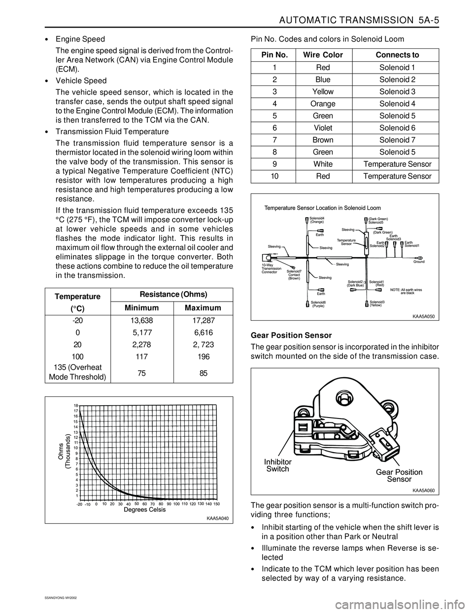
Transmission Fluid Temperature
The transmission fluid temperature sensor is a
thermistor located in the solenoid wiring loom within
the valve body of the transmission. This sensor is
a typical Negative Temperature Coefficient (NTC)
resistor with low temperatures producing a high
resistance and high temperatures producing a low
resistance.
If the transmission fluid temperature exceeds 135
°C (275 °F), the TCM will impose converter lock-up
at lower vehicle speeds and in some vehicles
flashes the mode indicator light. This results in
maximum oil flow through the external oil cooler and
eliminates slippage in the torque converter. Both
these actions combine to reduce the oil temperature
in the transmission.
Minimum Temperature
(°C)Resistance (Ohms)
-20
0
20
100
135 (Overheat
Mode Threshold)13,638
5,177
2,278
117
75
Maximum
17,287
6,616
2, 723
196
85
Pin No. Wire ColorConnects to
1 Red Solenoid 1
2 BlueSolenoid 2
3 YellowSolenoid 3
4 OrangeSolenoid 4
5 GreenSolenoid 5
6 VioletSolenoid 6
7 BrownSolenoid 7
8 GreenSolenoid 5
9 White Temperature Sensor
10 Red Temperature Sensor
Pin No. Codes and colors in Solenoid Loom
KAA5A040KAA5A050
Gear Position Sensor
The gear position sensor is incorporated in the inhibitor
switch mounted on the side of the transmission case.
Inhibit starting of the vehicle when the shift lever is
in a position other than Park or Neutral
Illuminate the reverse lamps when Reverse is se-
lected
Indicate to the TCM which lever position has been
selected by way of a varying resistance. The gear position sensor is a multi-function switch pro-
viding three functions;
KAA5A060
Page 1105 of 2053
AUTOMATIC TRANSMISSION 5A-11
SSANGYONG MY2002
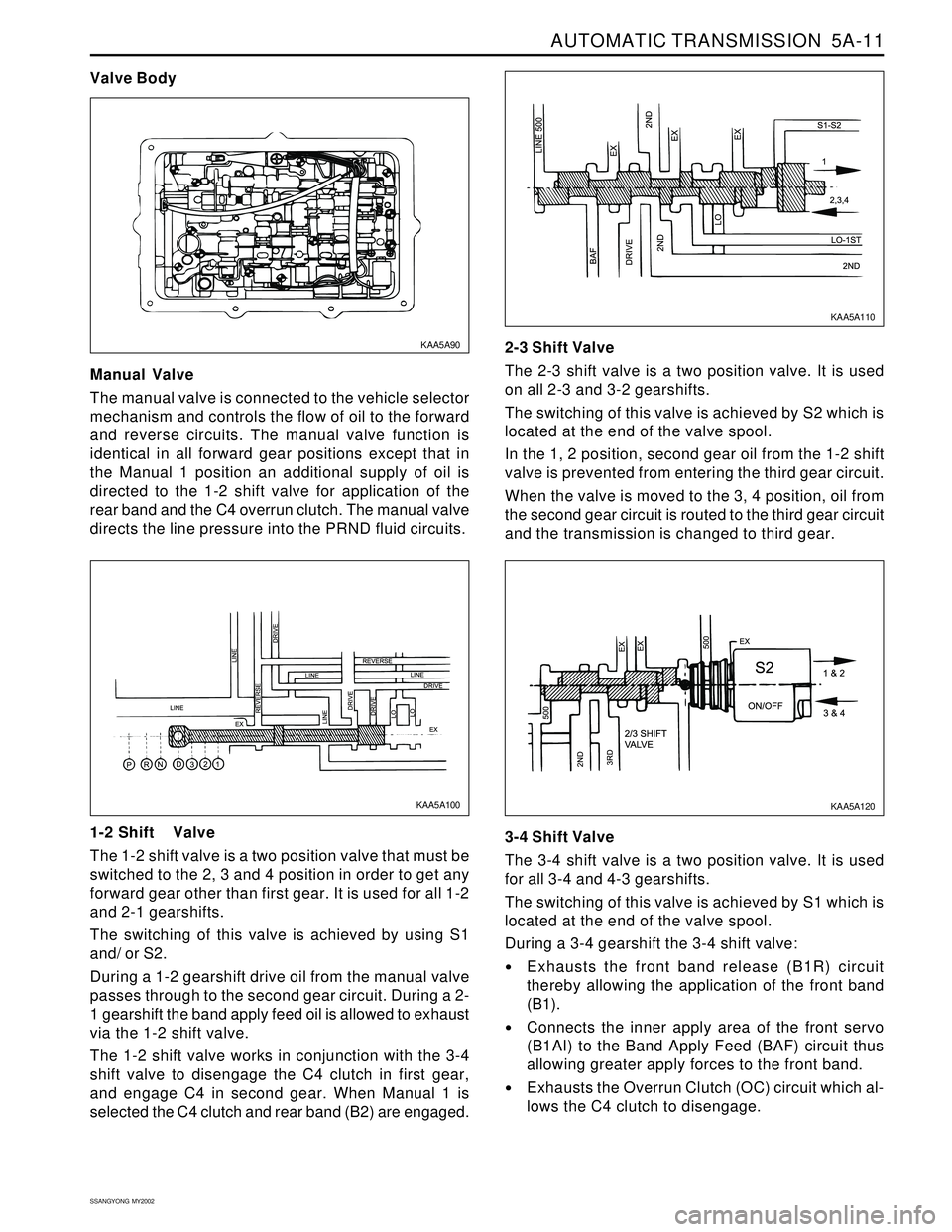
Manual Valve
The manual valve is connected to the vehicle selector
mechanism and controls the flow of oil to the forward
and reverse circuits. The manual valve function is
identical in all forward gear positions except that in
the Manual 1 position an additional supply of oil is
directed to the 1-2 shift valve for application of the
rear band and the C4 overrun clutch. The manual valve
directs the line pressure into the PRND fluid circuits.
Valve Body
1-2 Shift Valve
The 1-2 shift valve is a two position valve that must be
switched to the 2, 3 and 4 position in order to get any
forward gear other than first gear. It is used for all 1-2
and 2-1 gearshifts.
The switching of this valve is achieved by using S1
and/ or S2.
During a 1-2 gearshift drive oil from the manual valve
passes through to the second gear circuit. During a 2-
1 gearshift the band apply feed oil is allowed to exhaust
via the 1-2 shift valve.
The 1-2 shift valve works in conjunction with the 3-4
shift valve to disengage the C4 clutch in first gear,
and engage C4 in second gear. When Manual 1 is
selected the C4 clutch and rear band (B2) are engaged.2-3 Shift Valve
The 2-3 shift valve is a two position valve. It is used
on all 2-3 and 3-2 gearshifts.
The switching of this valve is achieved by S2 which is
located at the end of the valve spool.
In the 1, 2 position, second gear oil from the 1-2 shift
valve is prevented from entering the third gear circuit.
When the valve is moved to the 3, 4 position, oil from
the second gear circuit is routed to the third gear circuit
and the transmission is changed to third gear.
3-4 Shift Valve
The 3-4 shift valve is a two position valve. It is used
for all 3-4 and 4-3 gearshifts.
The switching of this valve is achieved by S1 which is
located at the end of the valve spool.
During a 3-4 gearshift the 3-4 shift valve:
Exhausts the front band release (B1R) circuit
thereby allowing the application of the front band
(B1).
Connects the inner apply area of the front servo
(B1AI) to the Band Apply Feed (BAF) circuit thus
allowing greater apply forces to the front band.
Exhausts the Overrun Clutch (OC) circuit which al-
lows the C4 clutch to disengage.
KAA5A100
KAA5A120 KAA5A90KAA5A110
Page 1109 of 2053
AUTOMATIC TRANSMISSION 5A-15
SSANGYONG MY2002
3-4
OWC
X
X
X
X
X 1-2
OWC
X B2
X
X B1
X
X C4
X
X
X
Gear set-sprag-centre support
C1 -C2 -C3 -C4 clutch sub-assembly
Pump assembly
Valve body assembly
One, or a combination of selective washers are used
between the input shaft flange and the number 4
bearing to control the transmission end float. This
arrangement allows for extensive subassembly testing
and simplistic final assembly during production.
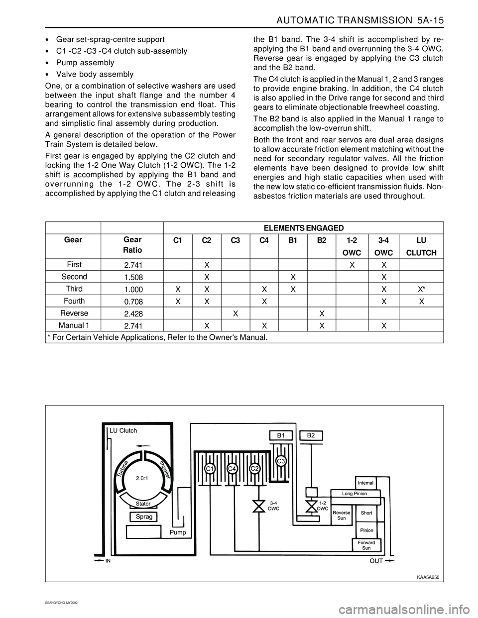
A general description of the operation of the Power
Train System is detailed below.
First gear is engaged by applying the C2 clutch and
locking the 1-2 One Way Clutch (1-2 OWC). The 1-2
shift is accomplished by applying the B1 band and
overrunning the 1-2 OWC. The 2-3 shift is
accomplished by applying the C1 clutch and releasingthe B1 band. The 3-4 shift is accomplished by re-
applying the B1 band and overrunning the 3-4 OWC.
Reverse gear is engaged by applying the C3 clutch
and the B2 band.
The C4 clutch is applied in the Manual 1, 2 and 3 ranges
to provide engine braking. In addition, the C4 clutch
is also applied in the Drive range for second and third
gears to eliminate objectionable freewheel coasting.
The B2 band is also applied in the Manual 1 range to
accomplish the low-overrun shift.
Both the front and rear servos are dual area designs
to allow accurate friction element matching without the
need for secondary regulator valves. All the friction
elements have been designed to provide low shift
energies and high static capacities when used with
the new low static co-efficient transmission fluids. Non-
asbestos friction materials are used throughout.
Gear
First
Second
Third
Fourth
Reverse
Manual 1Gear
Ratio
2.741
1.508
1.000
0.708
2.428
2.741C1
X
XC2
X
X
X
X
XC3
XLU
CLUTCH
X*
X ELEMENTS ENGAGED
* For Certain Vehicle Applications, Refer to the Owner's Manual.
KAA5A250