1997 SSANGYONG KORANDO oil type
[x] Cancel search: oil typePage 1409 of 2053
TRANSFER CASE (PART TIME - 4408) 5D2-9
SSANGYONG MY2002
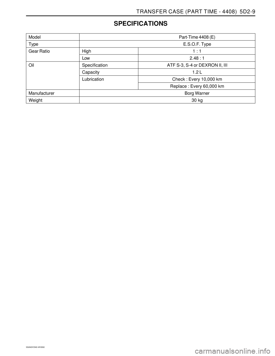
Model
Type
Gear Ratio
Oil
Manufacturer
WeightHigh
Low
Specification
Capacity
Lubrication
SPECIFICATIONS
Part-Time 4408 (E)
E.S.O.F. Type
1 : 1
2.48 : 1
ATF S-3, S-4 or DEXRON II, III
1.2 L
Check : Every 10,000 km
Replace : Every 60,000 km
Borg Warner
30 kg
Page 1446 of 2053
SSANGYONG MY2002
6A-4 POWER STEERING SYSTEM
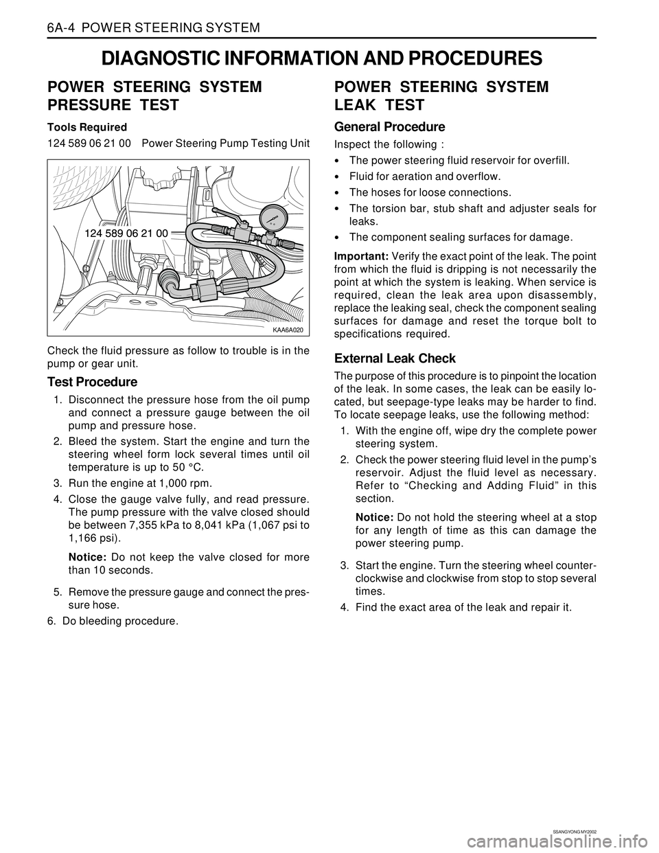
KAA6A020
DIAGNOSTIC INFORMATION AND PROCEDURES
POWER STEERING SYSTEM
PRESSURE TEST
Tools Required
124 589 06 21 00 Power Steering Pump Testing Unit
Check the fluid pressure as follow to trouble is in the
pump or gear unit.
Test Procedure
1. Disconnect the pressure hose from the oil pump
and connect a pressure gauge between the oil
pump and pressure hose.
2. Bleed the system. Start the engine and turn the
steering wheel form lock several times until oil
temperature is up to 50 °C.
3. Run the engine at 1,000 rpm.
4. Close the gauge valve fully, and read pressure.
The pump pressure with the valve closed should
be between 7,355 kPa to 8,041 kPa (1,067 psi to
1,166 psi).
Notice: Do not keep the valve closed for more
than 10 seconds.
5. Remove the pressure gauge and connect the pres-
sure hose.
6. Do bleeding procedure.
POWER STEERING SYSTEM
LEAK TEST
General Procedure
Inspect the following :
The power steering fluid reservoir for overfill.
Fluid for aeration and overflow.
The hoses for loose connections.
The torsion bar, stub shaft and adjuster seals for
leaks.
The component sealing surfaces for damage.
Important: Verify the exact point of the leak. The point
from which the fluid is dripping is not necessarily the
point at which the system is leaking. When service is
required, clean the leak area upon disassembly,
replace the leaking seal, check the component sealing
surfaces for damage and reset the torque bolt to
specifications required.
External Leak Check
The purpose of this procedure is to pinpoint the location
of the leak. In some cases, the leak can be easily lo-
cated, but seepage-type leaks may be harder to find.
To locate seepage leaks, use the following method:
1. With the engine off, wipe dry the complete power
steering system.
2. Check the power steering fluid level in the pump’s
reservoir. Adjust the fluid level as necessary.
Refer to “Checking and Adding Fluid” in this
section.
Notice: Do not hold the steering wheel at a stop
for any length of time as this can damage the
power steering pump.
3. Start the engine. Turn the steering wheel counter-
clockwise and clockwise from stop to stop several
times.
4. Find the exact area of the leak and repair it.
Page 1455 of 2053
SSANGYONG MY2002
6A-4 POWER STEERING SYSTEM
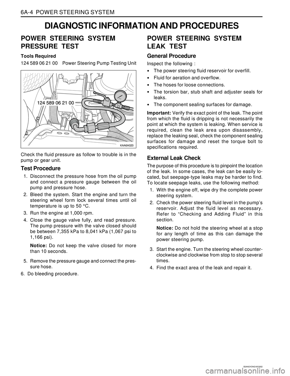
KAA6A020
DIAGNOSTIC INFORMATION AND PROCEDURES
POWER STEERING SYSTEM
PRESSURE TEST
Tools Required
124 589 06 21 00 Power Steering Pump Testing Unit
Check the fluid pressure as follow to trouble is in the
pump or gear unit.
Test Procedure
1. Disconnect the pressure hose from the oil pump
and connect a pressure gauge between the oil
pump and pressure hose.
2. Bleed the system. Start the engine and turn the
steering wheel form lock several times until oil
temperature is up to 50 °C.
3. Run the engine at 1,000 rpm.
4. Close the gauge valve fully, and read pressure.
The pump pressure with the valve closed should
be between 7,355 kPa to 8,041 kPa (1,067 psi to
1,166 psi).
Notice: Do not keep the valve closed for more
than 10 seconds.
5. Remove the pressure gauge and connect the pres-
sure hose.
6. Do bleeding procedure.
POWER STEERING SYSTEM
LEAK TEST
General Procedure
Inspect the following :
The power steering fluid reservoir for overfill.
Fluid for aeration and overflow.
The hoses for loose connections.
The torsion bar, stub shaft and adjuster seals for
leaks.
The component sealing surfaces for damage.
Important: Verify the exact point of the leak. The point
from which the fluid is dripping is not necessarily the
point at which the system is leaking. When service is
required, clean the leak area upon disassembly,
replace the leaking seal, check the component sealing
surfaces for damage and reset the torque bolt to
specifications required.
External Leak Check
The purpose of this procedure is to pinpoint the location
of the leak. In some cases, the leak can be easily lo-
cated, but seepage-type leaks may be harder to find.
To locate seepage leaks, use the following method:
1. With the engine off, wipe dry the complete power
steering system.
2. Check the power steering fluid level in the pump’s
reservoir. Adjust the fluid level as necessary.
Refer to “Checking and Adding Fluid” in this
section.
Notice: Do not hold the steering wheel at a stop
for any length of time as this can damage the
power steering pump.
3. Start the engine. Turn the steering wheel counter-
clockwise and clockwise from stop to stop several
times.
4. Find the exact area of the leak and repair it.
Page 1531 of 2053
SSANGYONG MY2002
7C-2 MANUAL & SEMIAUTO-HVAC
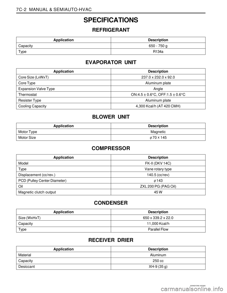
SPECIFICATIONS
REFRIGERANT
Core Size (LxWxT)
Core Type
Expansion Valve Type
Thermostat
Resister Type
Cooling CapacityApplicationDescription237.0 x 232.0 x 92.0
Aluminum plate
Angle
ON:4.5 ± 0.6°C, OFF:1.5 ± 0.6°C
Aluminum plate
4,300 Kcal/h (AT 420 CMH)
Capacity
TypeApplicationDescription650 - 750 g
R134a
EVAPORATOR UNIT
BLOWER UNIT
Motor Type
Motor SizeApplicationDescriptionMagnetic
φ 70 x
145
COMPRESSOR
Model
Type
Displacement (cc/rev.)
PCD (Pulley Center Diameter)
Oil
Magnetic clutch outputApplicationDescriptionFK-II (DKV 14C)
Vane rotary type
140.5 (cc/rev)
φ 143
ZXL 200 PG (PAG Oil)
45 W
CONDENSER
Size (WxHxT)
Capacity
TypeApplicationDescription650 x 339.2 x 22.0
11,000 Kcal/h
Parallel Flow
RECEIVER DRIER
Material
Capacity
DesiccantApplicationDescriptionAluminum
250 cc
XH-9 (35 g)
Page 1556 of 2053
SSANGYONG MY2002
7D-2 FATC-HAVC
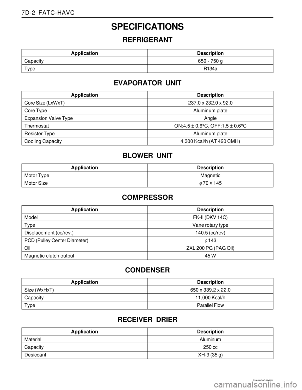
SPECIFICATIONS
REFRIGERANT
Core Size (LxWxT)
Core Type
Expansion Valve Type
Thermostat
Resister Type
Cooling CapacityApplicationDescription237.0 x 232.0 x 92.0
Aluminum plate
Angle
ON:4.5 ± 0.6°C, OFF:1.5 ± 0.6°C
Aluminum plate
4,300 Kcal/h (AT 420 CMH)
Capacity
TypeApplicationDescription650 - 750 g
R134a
EVAPORATOR UNIT
BLOWER UNIT
Motor Type
Motor SizeApplicationDescriptionMagnetic
φ 70 x
145
COMPRESSOR
Model
Type
Displacement (cc/rev.)
PCD (Pulley Center Diameter)
Oil
Magnetic clutch outputApplicationDescriptionFK-II (DKV 14C)
Vane rotary type
140.5 (cc/rev)
φ 143
ZXL 200 PG (PAG Oil)
45 W
CONDENSER
Size (WxHxT)
Capacity
TypeApplicationDescription650 x 339.2 x 22.0
11,000 Kcal/h
Parallel Flow
RECEIVER DRIER
Material
Capacity
DesiccantApplicationDescriptionAluminum
250 cc
XH-9 (35 g)
Page 1590 of 2053
SUPPLEMENTAL RESTRAINTS SYSTEM 8B-5
SSANGYONG MY2002
KAA8B060
AIRBAG WARNING LAMP
The instrument cluster contains an airbag warning indi-
cator bulb to verify the operation of the airbag indicator
and sensing and diagnostic module (SDM). The SDM
performs a start-up test when the ignition is turned ON
and turns the airbag indicator on for 4.5 seconds by
supplying an internal ground to the indicator lamp
circuit. After 4.5 seconds, the airbag indicator will turn
off if no more malfunctions have been detected.
If the SDM has detected malfunctions, which could
potentially affect the operation of the supplemental
restraint system (SRS) it turns on or blinks the airbag
warning indicator. The airbag indicator stays on for
the malfunction of internal system and blinks for
external circuit problem such as short to battery or
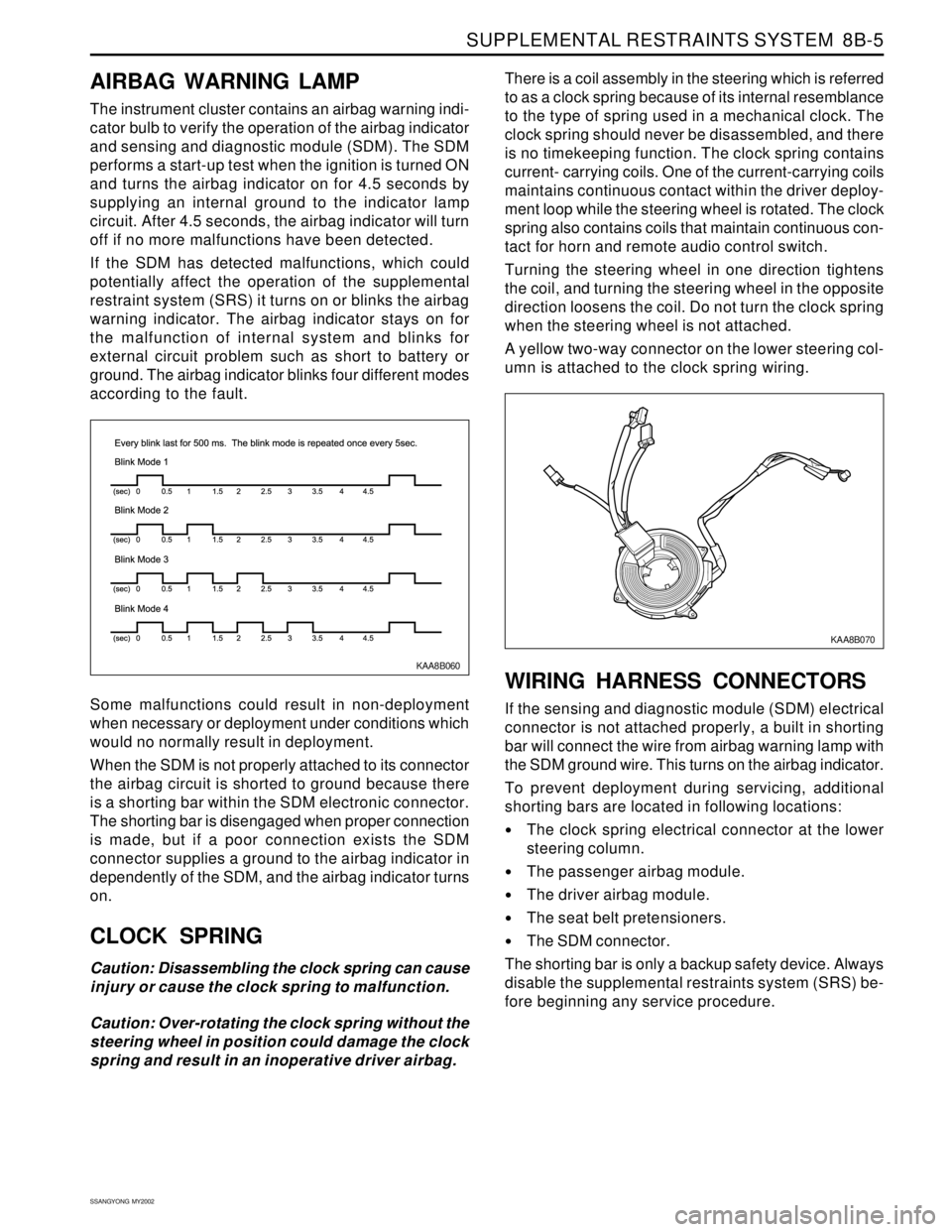
ground. The airbag indicator blinks four different modes
according to the fault.
Some malfunctions could result in non-deployment
when necessary or deployment under conditions which
would no normally result in deployment.
When the SDM is not properly attached to its connector
the airbag circuit is shorted to ground because there
is a shorting bar within the SDM electronic connector.
The shorting bar is disengaged when proper connection
is made, but if a poor connection exists the SDM
connector supplies a ground to the airbag indicator in
dependently of the SDM, and the airbag indicator turns
on.
CLOCK SPRING
Caution: Disassembling the clock spring can cause
injury or cause the clock spring to malfunction.
Caution: Over-rotating the clock spring without the
steering wheel in position could damage the clock
spring and result in an inoperative driver airbag.There is a coil assembly in the steering which is referred
to as a clock spring because of its internal resemblance
to the type of spring used in a mechanical clock. The
clock spring should never be disassembled, and there
is no timekeeping function. The clock spring contains
current- carrying coils. One of the current-carrying coils
maintains continuous contact within the driver deploy-
ment loop while the steering wheel is rotated. The clock
spring also contains coils that maintain continuous con-
tact for horn and remote audio control switch.
Turning the steering wheel in one direction tightens
the coil, and turning the steering wheel in the opposite
direction loosens the coil. Do not turn the clock spring
when the steering wheel is not attached.
A yellow two-way connector on the lower steering col-
umn is attached to the clock spring wiring.
WIRING HARNESS CONNECTORS
If the sensing and diagnostic module (SDM) electrical
connector is not attached properly, a built in shorting
bar will connect the wire from airbag warning lamp with
the SDM ground wire. This turns on the airbag indicator.
To prevent deployment during servicing, additional
shorting bars are located in following locations:
The clock spring electrical connector at the lower
steering column.
The passenger airbag module.
The driver airbag module.
The seat belt pretensioners.
The SDM connector.
The shorting bar is only a backup safety device. Always
disable the supplemental restraints system (SRS) be-
fore beginning any service procedure.
KAA8B070