1997 SSANGYONG KORANDO STARTING
[x] Cancel search: STARTINGPage 1098 of 2053

5A-4 AUTOMATIC TRANSMISSION
SSANGYONG MY2002
Output circuits which control external devices such
as the Variable Pressure Solenoid (VPS) driver, On/
Off solenoid drivers, a diagnostics output and the
driving mode indicator light.
Processing Logic
Shift schedule and calibration information is stored in
an Erasable Programmable Read Only Memory (EPROM).
Throttle input calibration constants and the diagnostics
information are stored in Electrically Erasable Program-
mable Read Only Memory (EEPROM) that retains the
memory even when power to the TCM is disconnected.
TCM continuously monitors the input values and uses
these, via the shift schedule, to determine the required
gear state. At the same time it monitors, via the solenoid
outputs, the current gear state, whenever the input
conditions change such that the required gear state is
different to the current gear state, the TCM initiates a
gear shift to bring the two states back into line.
Once the TCM has determined the type of gearshift
required the TCM accesses the shift logic, estimates
the engine torque output, adjusts the variable pressure
solenoid ramp pressure then executes the shift.The TCM continuously monitors every input and output
circuit for short or open circuits and operating range.
When a failure or abnormal operation is detected the
TCM records the condition code in the diagnostics
memory and implements a Limp Home Mode (LHM).
The actual limp home mode used depends upon the
failure detected with the object to maintain maximum
drive-ability without damaging the transmission. In
general input failures are handled by providing a default
value. Output failures, which are capable of damaging
the transmission, result in full limp mode giving only
third or fourth gear and reverse. For further details of
limp modes and memory retention refer to the
Diagnostic Trouble Code Diagnosis Section.
The TCM is designed to operate at ambient
temperatures between - 40 and 85 °C (- 40 and 185 °F).
It is also protected against electrical noise and voltage
spikes, however all the usual precautions should be
observed, for example when arc welding or jump
starting.
TCM Inputs
To function correctly, the TCM requires engine speed,
vehicle speed, transmission fluid temperature, throttle
position, gear position and Kickdown Switch inputs to
determine the variable pressure solenoid current ramp
and on/off solenoid states.
KAA5A030
This ensures the correct gear selection and shift feel
for all driving conditions.
The inputs required by the TCM are as follows;
Page 1099 of 2053
AUTOMATIC TRANSMISSION 5A-5
SSANGYONG MY2002
Engine Speed
The engine speed signal is derived from the Control-
ler Area Network (CAN) via Engine Control Module
(ECM).
Vehicle Speed
The vehicle speed sensor, which is located in the
transfer case, sends the output shaft speed signal
to the Engine Control Module (ECM). The information
is then transferred to the TCM via the CAN.
Transmission Fluid Temperature
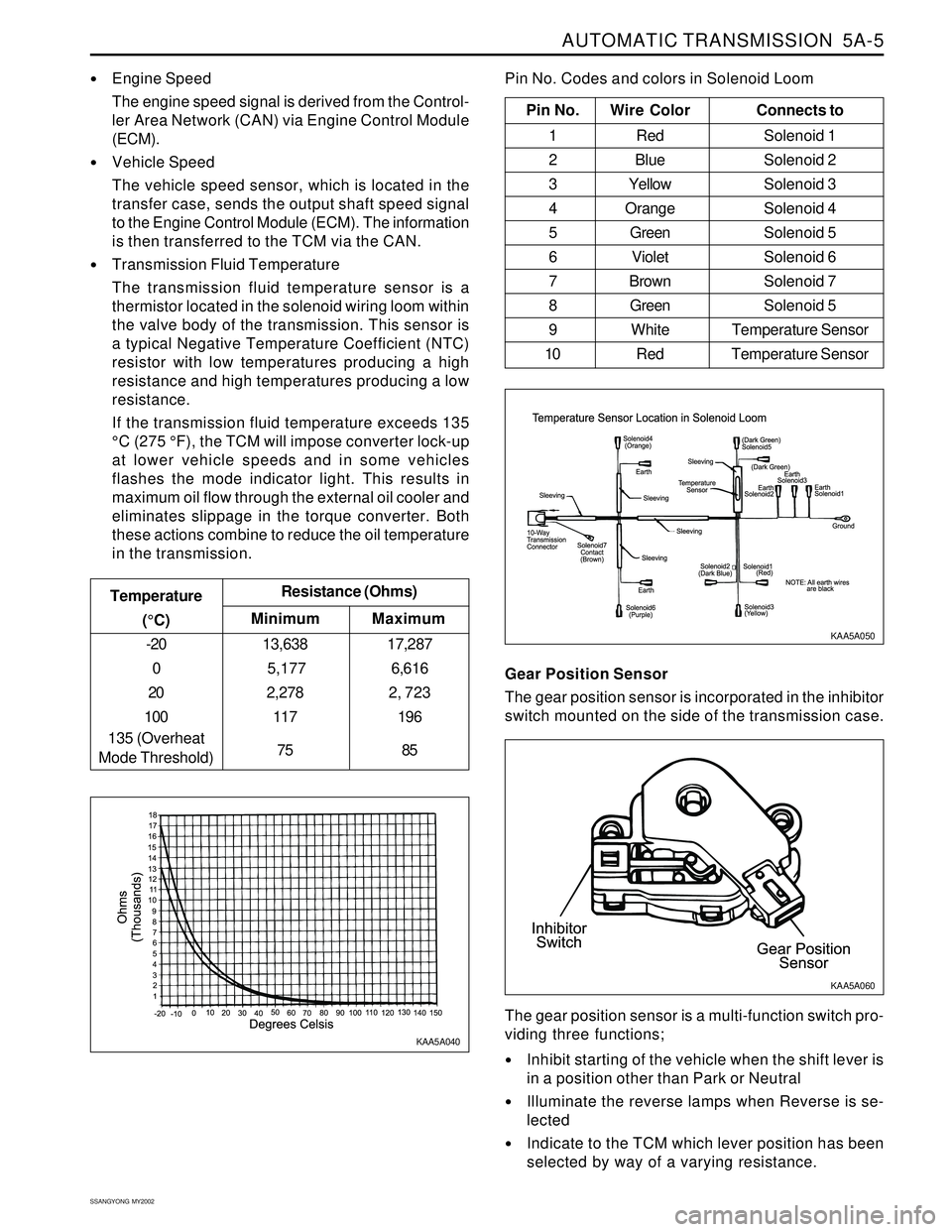
The transmission fluid temperature sensor is a
thermistor located in the solenoid wiring loom within
the valve body of the transmission. This sensor is
a typical Negative Temperature Coefficient (NTC)
resistor with low temperatures producing a high
resistance and high temperatures producing a low
resistance.
If the transmission fluid temperature exceeds 135
°C (275 °F), the TCM will impose converter lock-up
at lower vehicle speeds and in some vehicles
flashes the mode indicator light. This results in
maximum oil flow through the external oil cooler and
eliminates slippage in the torque converter. Both
these actions combine to reduce the oil temperature
in the transmission.
Minimum Temperature
(°C)Resistance (Ohms)
-20
0
20
100
135 (Overheat
Mode Threshold)13,638
5,177
2,278
117
75
Maximum
17,287
6,616
2, 723
196
85
Pin No. Wire ColorConnects to
1 Red Solenoid 1
2 BlueSolenoid 2
3 YellowSolenoid 3
4 OrangeSolenoid 4
5 GreenSolenoid 5
6 VioletSolenoid 6
7 BrownSolenoid 7
8 GreenSolenoid 5
9 White Temperature Sensor
10 Red Temperature Sensor
Pin No. Codes and colors in Solenoid Loom
KAA5A040KAA5A050
Gear Position Sensor
The gear position sensor is incorporated in the inhibitor
switch mounted on the side of the transmission case.
Inhibit starting of the vehicle when the shift lever is
in a position other than Park or Neutral
Illuminate the reverse lamps when Reverse is se-
lected
Indicate to the TCM which lever position has been
selected by way of a varying resistance. The gear position sensor is a multi-function switch pro-
viding three functions;
KAA5A060
Page 1147 of 2053
5A-52 AUTOMATIC TRANSMISSION
SSANGYONG MY2002
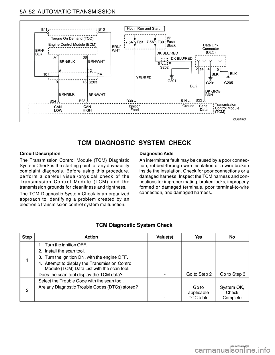
Circuit Description
The Transmission Control Module (TCM) Diagnistic
System Check is the starting point for any driveability
complaint diagnosis. Before using this procedure,
perform a careful visual/physical check of the
Transmission Control Module (TCM) and the
transmission grounds for cleanliness and tightness.
The TCM Diagnostic System Check is an organized
approach to identifying a problem created by an
electronic transmission control system malfunction.
TCM DIAGNOSTIC SYSTEM CHECK
Diagnostic Aids
An intermittent fault may be caused by a poor connec-
tion, rubbed-through wire insulation or a wire broken
inside the insulation. Check for poor connections or a
damaged harness. Inspect the TCM harness and con-
nections for improper mating, broken locks, improperly
formed or damaged terminals, poor terminal-to-wire
connection, and damaged harness.
TCM Diagnostic System Check
1
StepAction Value(s) Yes No
21 Turn the ignition OFF.
2. Install the scan tool.
3. Turn the ignition ON, with the engine OFF.
4. Attempt to display the Transmission Control
Module (TCM) Data List with the scan tool.
Does the scan tool display the TCM data?
Select the Trouble Code with the scan tool.
Are any Diagnostic Trouble Codes (DTCs) stored?
- Go to Step 2 Go to Step 3
Go to
applicable
DTC table -System OK,
Check
Complete
KAA5A5KA
Page 1161 of 2053
5A-66 AUTOMATIC TRANSMISSION
SSANGYONG MY2002
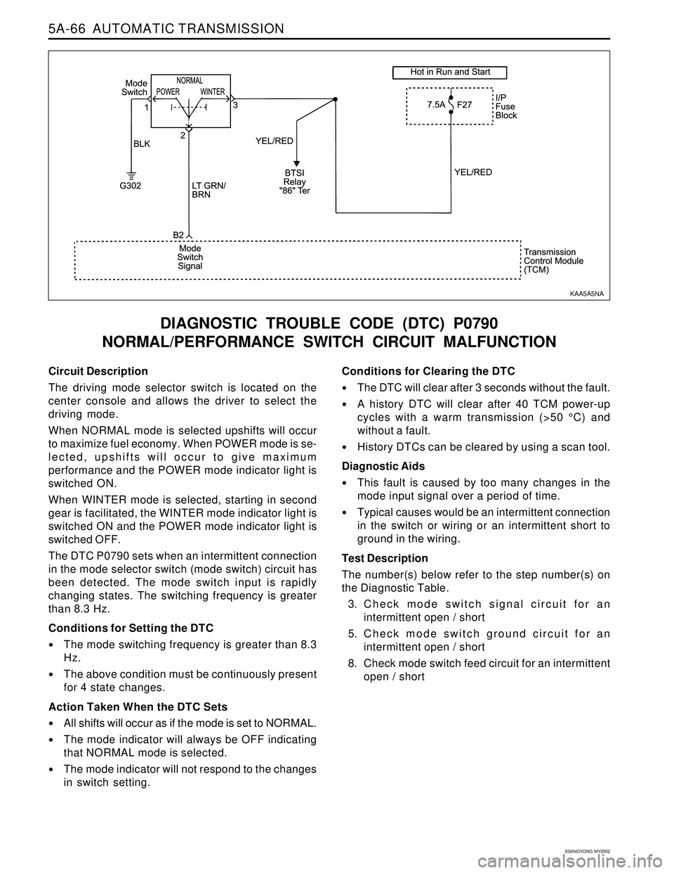
Circuit Description
The driving mode selector switch is located on the
center console and allows the driver to select the
driving mode.
When NORMAL mode is selected upshifts will occur
to maximize fuel economy. When POWER mode is se-
lected, upshifts will occur to give maximum
performance and the POWER mode indicator light is
switched ON.
When WINTER mode is selected, starting in second
gear is facilitated, the WINTER mode indicator light is
switched ON and the POWER mode indicator light is
switched OFF.
The DTC P0790 sets when an intermittent connection
in the mode selector switch (mode switch) circuit has
been detected. The mode switch input is rapidly
changing states. The switching frequency is greater
than 8.3 Hz.
Conditions for Setting the DTC
The mode switching frequency is greater than 8.3
Hz.
The above condition must be continuously present
for 4 state changes.
Action Taken When the DTC Sets
All shifts will occur as if the mode is set to NORMAL.
The mode indicator will always be OFF indicating
that NORMAL mode is selected.
The mode indicator will not respond to the changes
in switch setting.
DIAGNOSTIC TROUBLE CODE (DTC) P0790
NORMAL/PERFORMANCE SWITCH CIRCUIT MALFUNCTION
Conditions for Clearing the DTC
The DTC will clear after 3 seconds without the fault.
A history DTC will clear after 40 TCM power-up
cycles with a warm transmission (>50 °C) and
without a fault.
History DTCs can be cleared by using a scan tool.
Diagnostic Aids
This fault is caused by too many changes in the
mode input signal over a period of time.
Typical causes would be an intermittent connection
in the switch or wiring or an intermittent short to
ground in the wiring.
Test Description
The number(s) below refer to the step number(s) on
the Diagnostic Table.
3. Check mode switch signal circuit for an
intermittent open / short
5. Check mode switch ground circuit for an
intermittent open / short
8. Check mode switch feed circuit for an intermittent
open / short
KAA5A5NA
Page 1357 of 2053
Specifications.......................................................5C-2
General Specifications.........................................5C-2
Fastener Tightening Specifications.......................5C-2
Component Locator.............................................5C-3
Clutch Assembly.................................................5C-3
Pedal and Master Cylinder...................................5C-4
Maintenance and Repair.....................................5C-5
On-Vehicle Service.................................................5C-5
Bleeding of Clutch System...................................5C-5
Clutch Disc......................................................... 5C- 6
Master Cylinder.................................................5C-10Clutch Pedal...................................................... 5C-12
Clutch Oil Chamber........................................... 5C-14
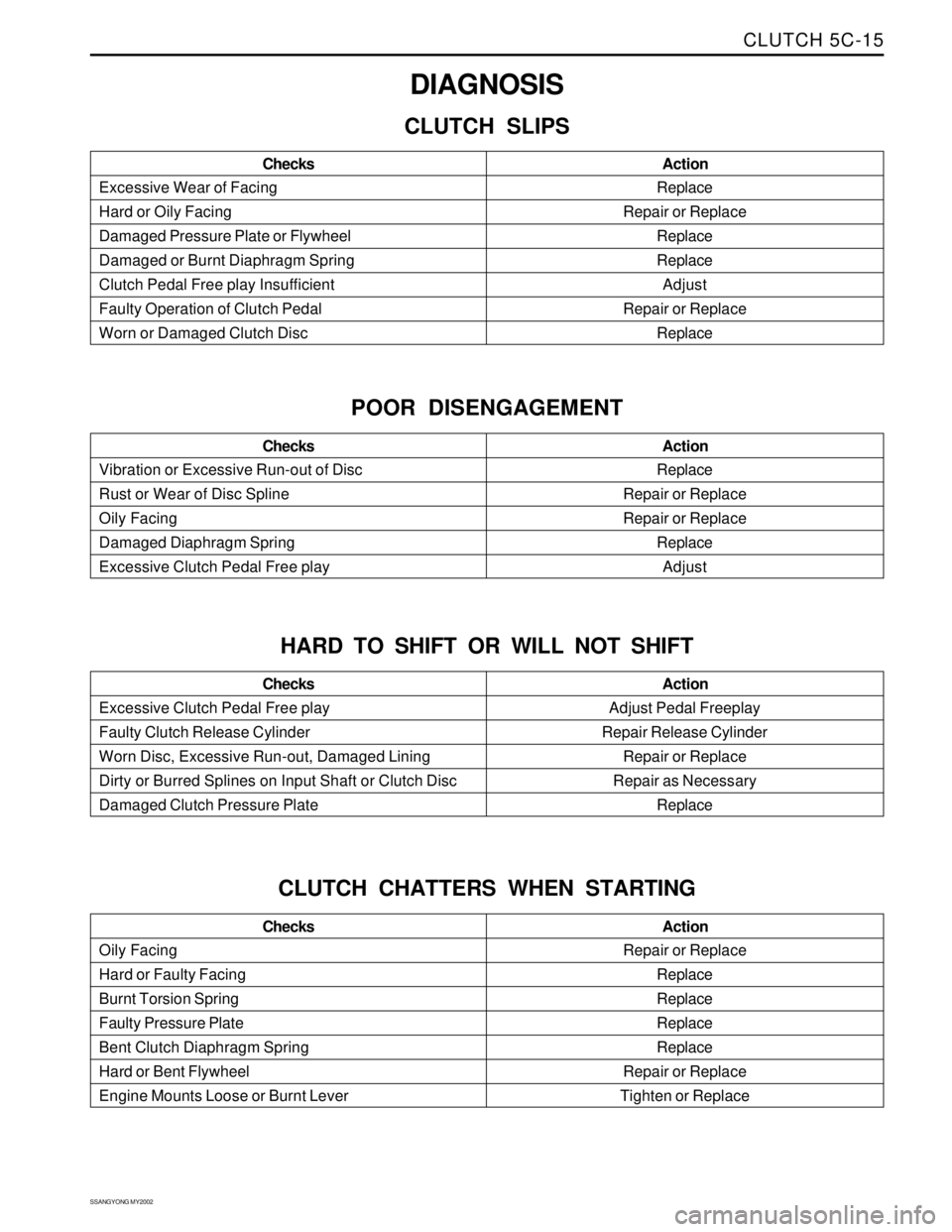
Diagnosis............................................................ 5C-15
Clutch Slips....................................................... 5C-15
Poor Disengagement ......................................... 5C-15
Hard to Shift or Will not Shift............................... 5C-15
Clutch Chatters When Starting........................... 5C-15
Difficult Pedal Operation.................................... 5C-16
Clutch Noisy...................................................... 5C-16
Special Tools and Equipment............................ 5C-17
Special Tools Table............................................ 5C-17
SECTION 5C
CLUTCH
CAUTION: Disconnect the negative battery cable before removing or installing any electrical unit or when a
tool or equipment could easily come in contact with exposed electrical terminals. Disconnecting this cable
will help prevent personal injury and damage to the vehicle. The ignition must also be in LOCK unless
otherwise noted.
TABLE OF CONTENTS
Page 1369 of 2053
CLUTCH 5C-15
SSANGYONG MY2002
Replace
Repair or Replace
Replace
Replace
Adjust
Repair or Replace
Replace Excessive Wear of Facing
Hard or Oily Facing
Damaged Pressure Plate or Flywheel
Damaged or Burnt Diaphragm Spring
Clutch Pedal Free play Insufficient
Faulty Operation of Clutch Pedal
Worn or Damaged Clutch DiscAction Checks
DIAGNOSIS
CLUTCH SLIPS
Replace
Repair or Replace
Repair or Replace
Replace
Adjust Vibration or Excessive Run-out of Disc
Rust or Wear of Disc Spline
Oily Facing
Damaged Diaphragm Spring
Excessive Clutch Pedal Free playAction Checks
POOR DISENGAGEMENT
Adjust Pedal Freeplay
Repair Release Cylinder
Repair or Replace
Repair as Necessary
Replace Excessive Clutch Pedal Free play
Faulty Clutch Release Cylinder
Worn Disc, Excessive Run-out, Damaged Lining
Dirty or Burred Splines on Input Shaft or Clutch Disc
Damaged Clutch Pressure PlateAction Checks
HARD TO SHIFT OR WILL NOT SHIFT
Repair or Replace
Replace
Replace
Replace
Replace
Repair or Replace
Tighten or Replace Oily Facing
Hard or Faulty Facing
Burnt Torsion Spring
Faulty Pressure Plate
Bent Clutch Diaphragm Spring
Hard or Bent Flywheel
Engine Mounts Loose or Burnt LeverAction Checks
CLUTCH CHATTERS WHEN STARTING
Page 1592 of 2053
SUPPLEMENTAL RESTRAINTS SYSTEM 8B-7
SSANGYONG MY2002
Driver Deployment Loop Shorted to Voltage
Passenger Deployment Loop Shorted to Voltage
Driver Seat Belt Pretensioner Shorted to Voltage
Passenger Seat Belt Pretensioner Shorted to Voltage
Driver Deployment Loop Shorted to Ground
Passenger Deployment Loop Shorted to Ground
Driver Seat Belt Pretensioner Shorted to Ground
Passenger Seat Belt Pretensioner Shorted to Ground
Driver Energy Shutdown Switch Error
Passenger Energy Shutdown Switch Error
Driver Seat Belt Pretensioner Energy Shutdown Switch Error
Passenger Seat Belt Pretensioner Energy Shutdown
Switch Error
Driver Ignition Switch Fault Internal
Passenger Ignition Switch Fault Internal
Driver Seat Belt Pretensioner Ignition Switch Fault
Passenger Seat Belt Pretensioner Ignition Switch Fault 01
02
03
04
05
06
07
08
09
10
11
12
13
14
15
16
DIAGNOSTIC INFORMATION AND PROCEDURES
DIAGNOSTIC TROUBLE CODES
(DTC)
When the sensing and diagnosticmodule (SDM)
detects any problem it illuminates or blinks the airbag
warning indicator and keeps the diagnostic trouble
codes (DTCs). The supplemental restraint system
(SRS) Diagnostic System Check must always be the
starting point for any SRS diagnosis. The SRS
Diagnostic System Check reveals DTCs through the
use of scan tool. It also checks for proper airbag
warning lamp operation.
The two types of DTCs that may be recorded are as
follows:
1. Current DTCs represent malfunction currently being
detected. Current DTCs are stored in random
access memory (RAM).
2. Historic DTCs represent malfunctions detected since
the last time the historic memory was cleared.
Historic DTCs are stored in the electrically erasable
programmable read-only memory (EEPROM).
The DTC is differentiates internal and external faults
upon the cause of the defects. Internal faults can not
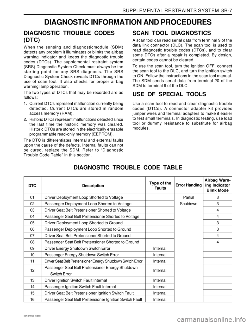
be cured, replace the SDM. Refer to “Diagnostic
Trouble Code Table” in this section.
SCAN TOOL DIAGNOSTICS
A scan tool can read serial data from terminal 9 of the
data link connector (DLC). The scan tool is used to
read diagnostic trouble codes (DTCs), and to clear
some DTCs after a repair is completed. By design,
certain codes cannot be cleared.
To use the scan tool, turn the ignition OFF, connect
the scan tool to the DLC, and turn the ignition switch
to ON. Follow the instructions in the scan tool manual.
The SDM sends serial data from terminal 20 of the
SDM to terminal 9 of the DLC.
USE OF SPECIAL TOOLS
Use a scan tool to read and clear diagnostic trouble
codes (DTCs). A connector adapter kit provides
jumper wires and terminal adapters to make it easier
to test small terminals. In diagnostic testing, use load
tool or dummy resistance to substitute for airbag
modules.
DIAGNOSTIC TROUBLE CODE TABLE
DTC DescriptionAirbag Warn-
ing Indicator
Blink Mode Error HandingType of the
Faults
Internal
Internal
Internal
Internal
Internal
Internal
Internal
Internal3
3
4
4
3
3
4
4
Partial
Shutdown
Page 1595 of 2053
SSANGYONG MY2002
8B-10 SUPPLEMENTAL RESTRAINTS SYSTEM
SRS DIAGNOSTIC SYSTEM CHECK
Notice: If the vehicle interior has been exposed to
extensive water intrusion such as water leaks, driving
through high water, flooding, or other caucuses, the
sensing and diagnostic module (SDM) and SDM
connector may be need to be replaced. With ignition
OFF, inspect the area around the SDM, including the
carpet. If any significant soaking or evidence of previous
soaking is detected, the water must be removed, water
damage repaired, and the SDM and SDM connector must
be replaced. Before attempting any of these repairs, the
supplemental restraint system (SRS) must be disabled.
Refer to “Disabling the SRS” and “Sensing and
Diagnostic Module (SDM)” in this section.
The SRS Diagnostic System Check must always be
the starting point for any SRS system diagnosis. The
SRS Diagnostic System Check reveals diagnostic
trouble codes (DTCs) through the use of scan tool.
The diagnostic procedures used in this section are
designed to find and repair SRS conditions. To get
the best results, it is important to use the diagnostic
charts and follow the sequence listed below.
1. Perform the SRS Diagnostic System Check, which
reveals diagnostic trouble codes (DTCs) through
the use of scan tool. It also checks for proper airbag
indicator operation.
2. Refer to the proper diagnostic chart as directed by
SRS Diagnostic System Check. Bypassing these
procedures may result in extended diagnostic time,
incorrect diagnosis, and incorrect parts
replacement.3. Repeat the SRS Diagnostic System Check after any
repair or diagnostic procedures have been
performed to ensure that the repair has beenmade
correctly and that no other malfunction exists.
Circuit Description
When the ignitions witch is first turned to ON, ignition
voltage is supplied from airbag fuse to the SDM at
input terminal 5. The SDM responds by turning on the
airbag indicator for 4.5 seconds and then turning it off
while the SDM performs tests on the SRS system.
Diagnostic Aids
The order in which DTCs are diagnosed is very
important. Failure to diagnose the DTCs in the order
specified may result in extended diagnostic time,
incorrect diagnosis, and incorrect parts replacement.
Test Description
The numbers below refer to steps on the diagnostic
table.
2. This test differentiates between an indicator that
will not come on and an indicator that stays on when
it should be off.
3. Refer to the first caution below
5. This test, along with step 6, differentiates internal
or external faults of SDM.
9. Refer to the cautions below.