Page 870 of 2053
SSAMGYONG MY2002
3A-8 FRONT AXLE
Removal & Installation Procedure
1. Remove the tire.
Installation Notice
2. Remove the autolocking hub vacuum hose.
3. With ABS
Remove the wheel speed sensor from the steering
knuckle.
Installation Notice
4. Remove the mounting bolts and pull off the caliper
assembly.
Installation Notice
Notice: Be careful not to damage the brake hose.
KAA3A070
KAA3A080
KAA3A090
KAA3A100
Tightening
Torque80 - 120 Nm
(59 - 89 lb-ft)
110 - 130 Nm
(81 - 96 lb-ft)Steel Wheel
Aluminum
Wheel
Tightening Torque6 - 8 Nm
(53 - 71 lb-in)
Tightening
Torque25 - 35 Nm
(18 - 26 lb-ft)
85 - 105 Nm
(63 - 77 lb-ft)Hose Bolt
Mounting
Bolt
Page 956 of 2053

SSANGYONG MY2002
4D-6 FRONT BRAKES
KAA4D080
FRONT DISC BRAKE ROTOR
Removal and Installation Procedure
1. Raise and suitably support the vehicle.
2. Remove the front wheels. Refer to Section 2E,
Tires and Wheels.
3. Remove the hub bearing assembly. Refer to
Section 2C, Front Suspension.
4. Remove the front disc brake rotor.
5. Installation should follow the removal procedure in
the reverse order.
KAA4D040
REPAIR INSTRUCTIONS
ON-VEHICLE SERVICE
BRAKE PADS
Removal and Installation Procedure
1. Raise and suitably support the vehicle.
2. Remove the front wheels. Refer to Section 2E,
Tires and Wheels.
3. Remove the caliper guide lower bolt.
Important: Caliper assembly removal is not
necessary to service the brake pad.
Installation Notice
Take care not to damage the piston seal when
the retaining frame is pulled down.
Tightening Torque 31 Nm (23 lb-ft)
KAA4D050
4. Remove the brake pads.
Installation Notice:
Measure the minimum brake pad thickness.
Refer to “Lining Inspection” in this section.
Always change the all pads on one wheel at a
time.
5. Installation should follow the removal procedure in
the reverse order.
Page 957 of 2053

FRONT BRAKES 4D-7
SSANGYONG MY2002
KAA4D060
KAA4D070
CALIPER ASSEMBLY
Removal and Installation Procedure
1. Raise and suitably support the vehicle.
2. Remove the front wheels. Refer to Section 2E,
Tires and Wheels.
3. Remove the brake hose mounting nut and
disconnect the hose. Plug the openings in the
caliper and the brake hose to prevent fluid loss
and contamination.
Installation Notice
Tightening Torque 30 Nm (22 lb-ft)
4. Remove the caliper mounting bolts and then
remove the caliper assembly.
Installation Notice
Tightening Torque 95 Nm (70 lb-ft)
Bleed the caliper. Refer to Section 4A, Hydraulic
Brakes.
Notice: do not move the vehicle until a firm pedal
is obtained or improper braking action will result.
Repeatedly press the brake pedal to bring the
pads in contact with the rotor.
5. Installation should follow the removal procedure
in the reverse order.
SPLASH SHIELD
Removal and Installation Procedure
1. Raise and suitably support the vehicle.
2. Remove the front wheels. Refer to Section 2E,
Tires and Wheels.
3. Remove the hub bearing assembly. Refer to
Section 2C, Front Suspension.
4. Remove the front disc brake rotor. Refer to “Front
Disc Brake Rotor” in this section.
5. Remove the splash shield bolt.
Installation Notice
KAA4D090
Tightening Torque 6 Nm (53 lb-ft)
6. Installation should follow the removal procedure
in the reverse order.
Page 979 of 2053
REAR BRAKES 4E-19
SSANGYONG MY2002
9. Remove the wheel cylinder mounting bolt and
remove the wheel cylinder.
Inspection
1. Measure the inside diameter of the brake drum
and replace as needed.
I.D.
φ 254 mmWear Limitφ 255.5 mm
Notice: Measure two more position.
2. Inspect the surface between the lining and brake.
Mark the brake drum inside using chalk and scrub
the shoe & lining assembly. If there is excessive
contact problem, replace the shoe & lining
assembly or the brake drum.
Notice: Clean any chalk mark after inspection
complete.
YAD4C370
YAD4C380
YAD4C390
Installation Procedure
1. Install the wheel cylinder to the backing plate.
Installation Notice
Tightening Torque8 - 12 Nm
(71 - 106 lb-in)
YAD4C400
Page 982 of 2053
SSANGYONG MY2002
4E-22 REAR BRAKES
UNIT REPAIR
WHEEL CYLINDER
Disassembly Procedure
1. Remove the upper brake return spring and remove
the wheel cylinder with pulling the upper lining
outside.
2. Disassembly the wheel cylinder assembly.
Remove the dust boot and do not reuse them
(1).
Remove the piston (2).
Remove the piston cup and do not reuse it (3).
Remove the spring assembly (4).
Remove the bleeder screw (5).
3. Clean all the parts with the denatured alcohol. Dry
the parts with unlubricated compressed air.
Bleeder Screw7 - 10 Nm
(62 - 89 lb-in)
8 - 12 Nm
(71 - 106 lb-in)
Wheel Cylinder
Mounting Bolt
Notice: Lubricate the new seals, the piston, the
piston cup and the wheel cylinder bore with clean
brake fluid before assembly. 4. Installation should follow the removal procedure
in the reverse order.
5. Tighten the bleeder screw and wheel cylinder as
specified torque.
YAD4C460
YAD4C470
YAD4C480
Page 1084 of 2053

ABS AND TCS 4F-101
SSANGYONG MY2002
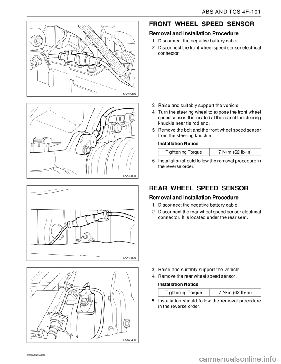
FRONT WHEEL SPEED SENSOR
Removal and Installation Procedure
1. Disconnect the negative battery cable.
2. Disconnect the front wheel speed sensor electrical
connector.
3. Raise and suitably support the vehicle.
4. Turn the steering wheel to expose the front wheel
speed sensor. It is located at the rear of the steering
knuckle near tie rod end.
5. Remove the bolt and the front wheel speed sensor
from the steering knuckle.
Installation Notice
KAA4F370
KAA4F380
Tightening Torque 7 Nm (62 lb-in)
6. Installation should follow the removal procedure in
the reverse order.
REAR WHEEL SPEED SENSOR
Removal and Installation Procedure
1. Disconnect the negative battery cable.
2. Disconnect the rear wheel speed sensor electrical
connector. It is located under the rear seat.
3. Raise and suitably support the vehicle.
4. Remove the rear wheel speed sensor.
Installation Notice
KAA4F390
KAA4F400
Tightening Torque 7 Nm (62 lb-in)
5. Installation should follow the removal procedure
in the reverse order.
Page 1330 of 2053

SSANGYONG MY2002
5B-22 MANUAL TRANSMISSION
62 - 93 Nm
(45 - 69 lb-ft)
21 - 35 Nm
(15 - 26 lb-ft)
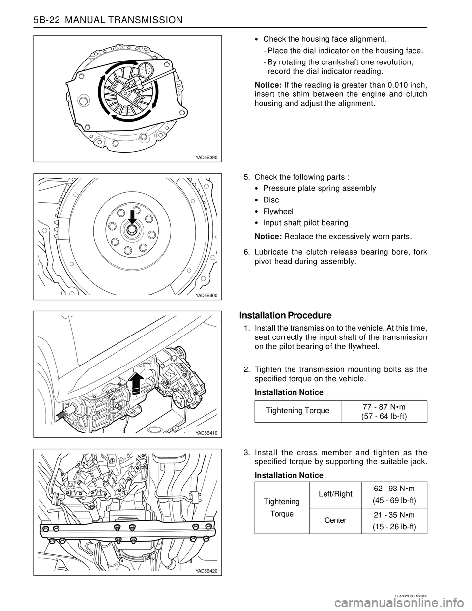
Check the housing face alignment.
- Place the dial indicator on the housing face.
- By rotating the crankshaft one revolution,
record the dial indicator reading.
Notice: If the reading is greater than 0.010 inch,
insert the shim between the engine and clutch
housing and adjust the alignment.
5. Check the following parts :
Pressure plate spring assembly
Disc
Flywheel
Input shaft pilot bearing
Notice: Replace the excessively worn parts.
6. Lubricate the clutch release bearing bore, fork
pivot head during assembly.
Installation Procedure
1. Install the transmission to the vehicle. At this time,
seat correctly the input shaft of the transmission
on the pilot bearing of the flywheel.
2. Tighten the transmission mounting bolts as the
specified torque on the vehicle.
Installation Notice
YAD5B390
YAD5B400
YAD5B410
YAD5B420
Tightening Torque77 - 87 Nm
(57 - 64 lb-ft)
3. Install the cross member and tighten as the
specified torque by supporting the suitable jack.
Installation Notice
Tightening
TorqueLeft/Right
Center
Page 1362 of 2053
CLUTCH 5C-7
SSANGYONG MY2002
Removal & Installation Procedure
Tools Required
602589 00 40 00 Engine Lock
1. Remove the starter motor. Install the special tool
to the flywheel through the starter motor mounting
holes.
2. Unscren the release cylinder mounting bolts and
remove the release cylinder.
Installation Notice
3. Unscrew the clutch housing bolts and remove the
clutch housing, release fork and release bearing.
Installation Notice
4. Insert the centering pin into the clutch spline.
Loosen the clutch cover bolts 1/2 turn in crisscross
sequence until the spring tension is released.
Notice: Do not remove the bolts at a time, or
clutchcover can be damaged or deformed.
Tools Required
Centering Pin 661 589 00 15 00
KAA5C050
KAA5C060
KAA5C070
KAA5C080
Tightening Torque15 - 18 Nm
(11 - 13 lb-ft)
Tightening Torque 54 Nm (40 lb-ft)