1997 SSANGYONG KORANDO wheel bolt torque
[x] Cancel search: wheel bolt torquePage 1363 of 2053
SSAMGYONG MY2002
5C-8 CLUTCH
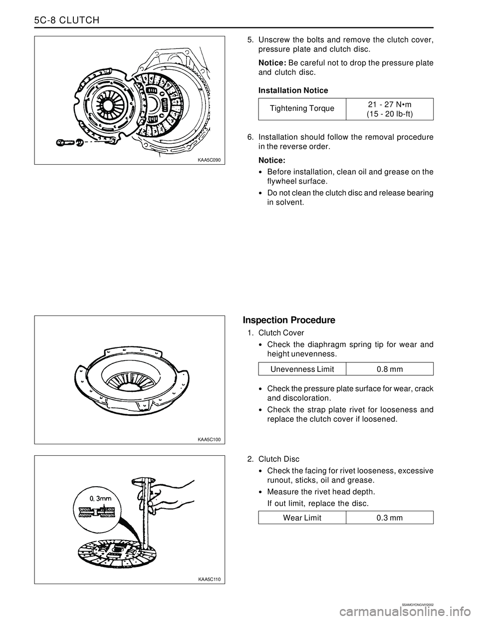
5. Unscrew the bolts and remove the clutch cover,
pressure plate and clutch disc.
Notice: Be careful not to drop the pressure plate
and clutch disc.
Installation Notice
6. Installation should follow the removal procedure
in the reverse order.
Notice:
Before installation, clean oil and grease on the
flywheel surface.
Do not clean the clutch disc and release bearing
in solvent.
2. Clutch Disc
Check the facing for rivet looseness, excessive
runout, sticks, oil and grease.
Measure the rivet head depth.
If out limit, replace the disc.
Inspection Procedure
1. Clutch Cover
Check the diaphragm spring tip for wear and
height unevenness.
Check the pressure plate surface for wear, crack
and discoloration.
Check the strap plate rivet for looseness and
replace the clutch cover if loosened.
KAA5C090
KAA5C100
KAA5C110
Tightening Torque21 - 27 Nm
(15 - 20 lb-ft)
Wear Limit 0.3 mm
Unevenness Limit 0.8 mm
Page 1399 of 2053
TRANSFER CASE 5D1-77
SSANGYONG MY2002
KAA5D420
KAA5D590
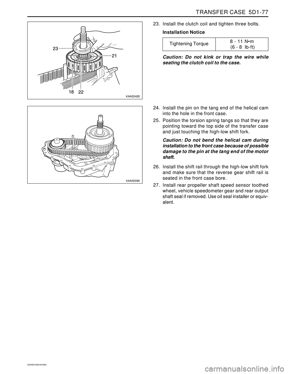
23. Install the clutch coil and tighten three bolts.
Installation Notice
Caution: Do not kink or trap the wire while
seating the clutch coil to the case.
24. Install the pin on the tang end of the helical cam
into the hole in the front case.
25. Position the torsion spring tangs so that they are
pointing toward the top side of the transfer case
and just touching the high-low shift fork.
Caution: Do not bend the helical cam during
installation to the front case because of possible
damage to the pin at the tang end of the motor
shaft.
26. Install the shift rail through the high-low shift fork
and make sure that the reverse gear shift rail is
seated in the front case bore.
27. Install rear propeller shaft speed sensor toothed
wheel, vehicle speedometer gear and rear output
shaft seal if removed. Use oil seal installer or equiv-
alent.
Tightening Torque8 - 11 Nm
(6 - 8 lb-ft)
Page 1446 of 2053
SSANGYONG MY2002
6A-4 POWER STEERING SYSTEM
KAA6A020
DIAGNOSTIC INFORMATION AND PROCEDURES
POWER STEERING SYSTEM
PRESSURE TEST
Tools Required
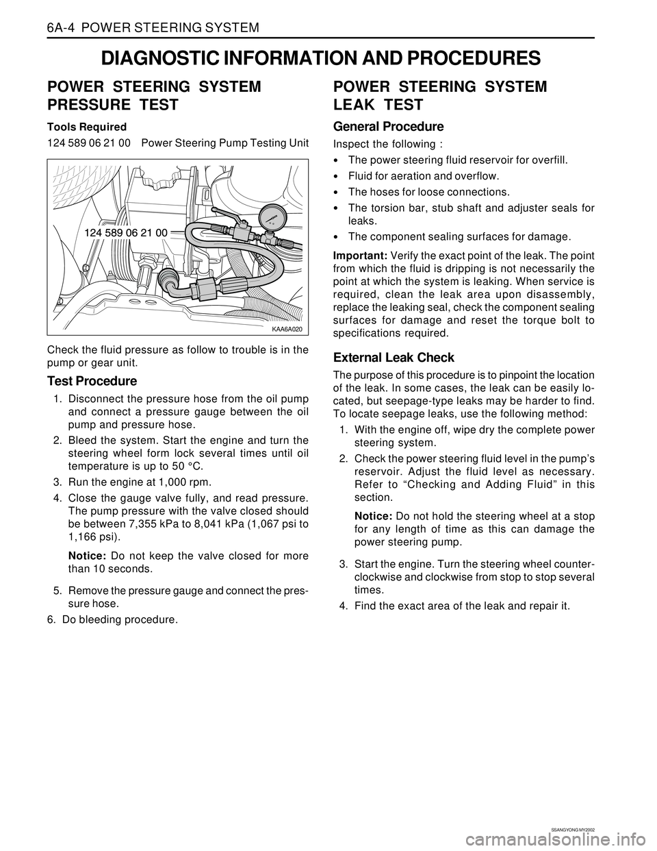
124 589 06 21 00 Power Steering Pump Testing Unit
Check the fluid pressure as follow to trouble is in the
pump or gear unit.
Test Procedure
1. Disconnect the pressure hose from the oil pump
and connect a pressure gauge between the oil
pump and pressure hose.
2. Bleed the system. Start the engine and turn the
steering wheel form lock several times until oil
temperature is up to 50 °C.
3. Run the engine at 1,000 rpm.
4. Close the gauge valve fully, and read pressure.
The pump pressure with the valve closed should
be between 7,355 kPa to 8,041 kPa (1,067 psi to
1,166 psi).
Notice: Do not keep the valve closed for more
than 10 seconds.
5. Remove the pressure gauge and connect the pres-
sure hose.
6. Do bleeding procedure.
POWER STEERING SYSTEM
LEAK TEST
General Procedure
Inspect the following :
The power steering fluid reservoir for overfill.
Fluid for aeration and overflow.
The hoses for loose connections.
The torsion bar, stub shaft and adjuster seals for
leaks.
The component sealing surfaces for damage.
Important: Verify the exact point of the leak. The point
from which the fluid is dripping is not necessarily the
point at which the system is leaking. When service is
required, clean the leak area upon disassembly,
replace the leaking seal, check the component sealing
surfaces for damage and reset the torque bolt to
specifications required.
External Leak Check
The purpose of this procedure is to pinpoint the location
of the leak. In some cases, the leak can be easily lo-
cated, but seepage-type leaks may be harder to find.
To locate seepage leaks, use the following method:
1. With the engine off, wipe dry the complete power
steering system.
2. Check the power steering fluid level in the pump’s
reservoir. Adjust the fluid level as necessary.
Refer to “Checking and Adding Fluid” in this
section.
Notice: Do not hold the steering wheel at a stop
for any length of time as this can damage the
power steering pump.
3. Start the engine. Turn the steering wheel counter-
clockwise and clockwise from stop to stop several
times.
4. Find the exact area of the leak and repair it.
Page 1455 of 2053
SSANGYONG MY2002
6A-4 POWER STEERING SYSTEM
KAA6A020
DIAGNOSTIC INFORMATION AND PROCEDURES
POWER STEERING SYSTEM
PRESSURE TEST
Tools Required
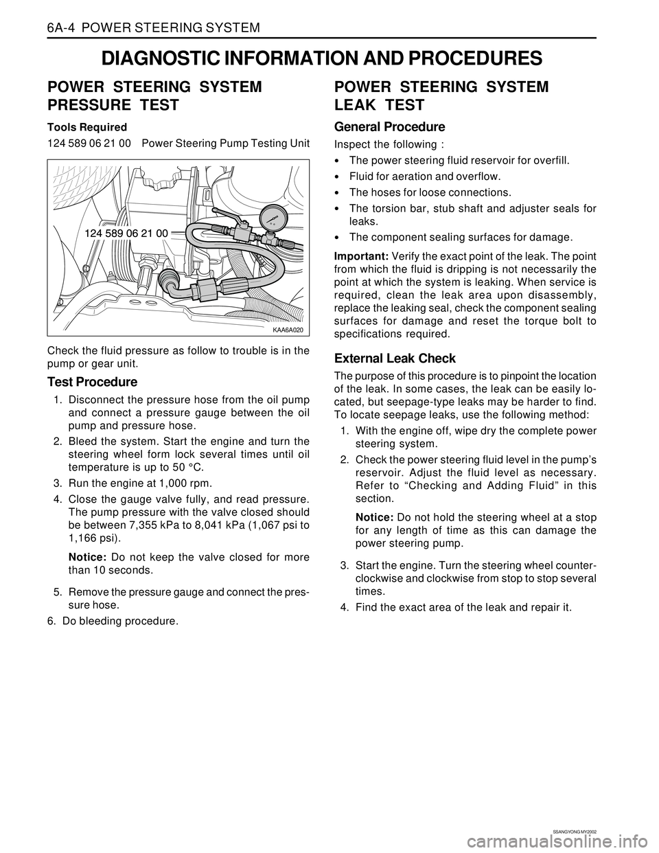
124 589 06 21 00 Power Steering Pump Testing Unit
Check the fluid pressure as follow to trouble is in the
pump or gear unit.
Test Procedure
1. Disconnect the pressure hose from the oil pump
and connect a pressure gauge between the oil
pump and pressure hose.
2. Bleed the system. Start the engine and turn the
steering wheel form lock several times until oil
temperature is up to 50 °C.
3. Run the engine at 1,000 rpm.
4. Close the gauge valve fully, and read pressure.
The pump pressure with the valve closed should
be between 7,355 kPa to 8,041 kPa (1,067 psi to
1,166 psi).
Notice: Do not keep the valve closed for more
than 10 seconds.
5. Remove the pressure gauge and connect the pres-
sure hose.
6. Do bleeding procedure.
POWER STEERING SYSTEM
LEAK TEST
General Procedure
Inspect the following :
The power steering fluid reservoir for overfill.
Fluid for aeration and overflow.
The hoses for loose connections.
The torsion bar, stub shaft and adjuster seals for
leaks.
The component sealing surfaces for damage.
Important: Verify the exact point of the leak. The point
from which the fluid is dripping is not necessarily the
point at which the system is leaking. When service is
required, clean the leak area upon disassembly,
replace the leaking seal, check the component sealing
surfaces for damage and reset the torque bolt to
specifications required.
External Leak Check
The purpose of this procedure is to pinpoint the location
of the leak. In some cases, the leak can be easily lo-
cated, but seepage-type leaks may be harder to find.
To locate seepage leaks, use the following method:
1. With the engine off, wipe dry the complete power
steering system.
2. Check the power steering fluid level in the pump’s
reservoir. Adjust the fluid level as necessary.
Refer to “Checking and Adding Fluid” in this
section.
Notice: Do not hold the steering wheel at a stop
for any length of time as this can damage the
power steering pump.
3. Start the engine. Turn the steering wheel counter-
clockwise and clockwise from stop to stop several
times.
4. Find the exact area of the leak and repair it.
Page 1477 of 2053
POWER STEERING GEAR 6C-9
SSANGYONG MY2002
KAA6C140
KAA6C050
KAA6C050
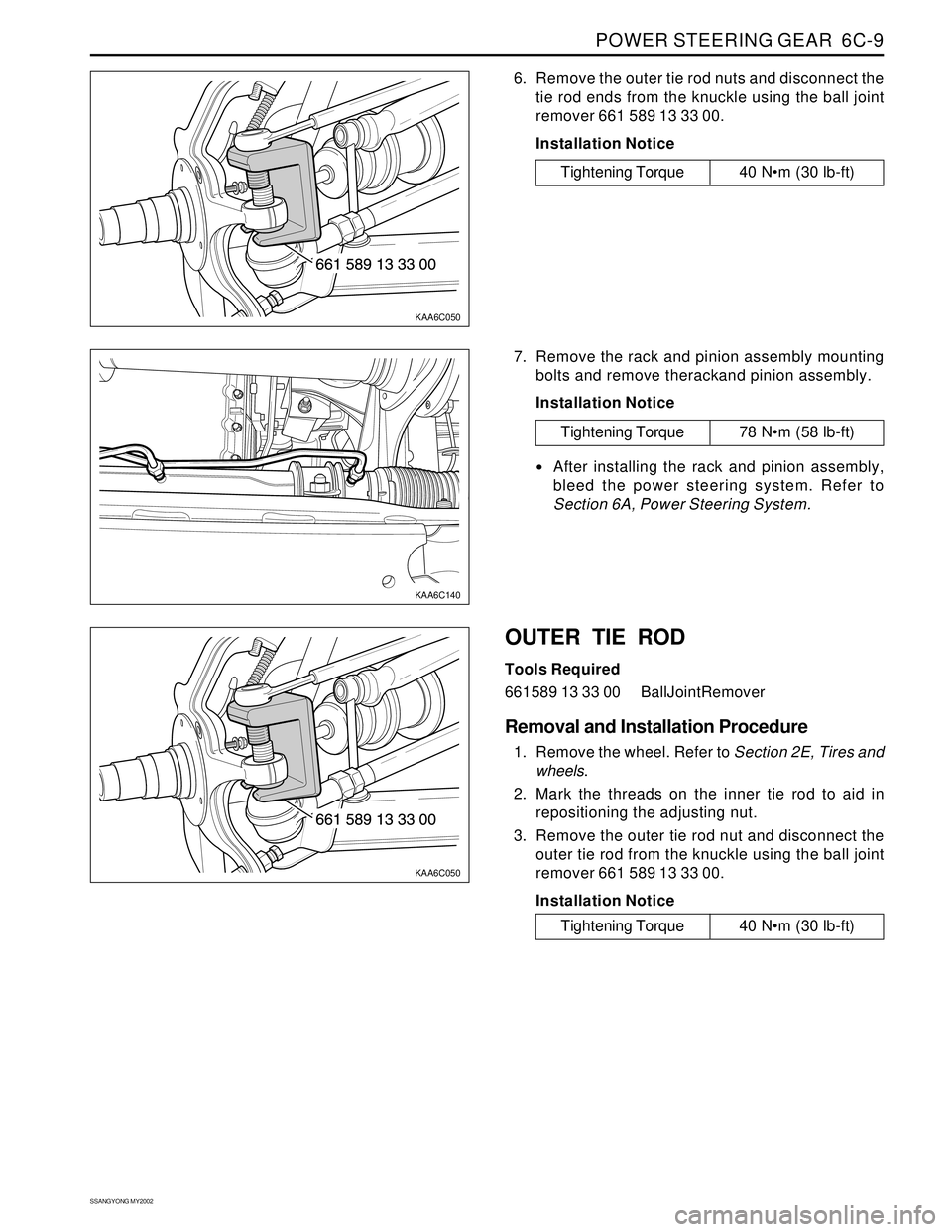
6. Remove the outer tie rod nuts and disconnect the
tie rod ends from the knuckle using the ball joint
remover 661 589 13 33 00.
Installation Notice
7. Remove the rack and pinion assembly mounting
bolts and remove therackand pinion assembly.
Installation Notice
Tightening Torque 40 Nm (30 lb-ft)
After installing the rack and pinion assembly,
bleed the power steering system. Refer to
Section 6A, Power Steering System.
OUTER TIE ROD
Tools Required
661589 13 33 00 BallJointRemover
Removal and Installation Procedure
1. Remove the wheel. Refer to Section 2E, Tires and
wheels.
2. Mark the threads on the inner tie rod to aid in
repositioning the adjusting nut.
3. Remove the outer tie rod nut and disconnect the
outer tie rod from the knuckle using the ball joint
remover 661 589 13 33 00.
Installation Notice
Tightening Torque 78 Nm (58 lb-ft)
Tightening Torque 40 Nm (30 lb-ft)
Page 1488 of 2053
SSANGYONG MY2002
6E-2 POWER STEERING AND COLUMN
GENERAL DESCRIPTION
Caution: To ensure the energy-absorbing action of
the steering column, it is important to use only the
specified screws, bolts, and nuts, tightened to the
specified torque.
In addition to the steering function, the steering column
provides safety and security.
The energy-absorbing column is designed to compress
in a front-end collision to lessen the chance of driver
injury.
The ignition switch and the lock are mounted on the
column, allowing the ignition and steering operations
to be locked to inhibit theft of the car.
The column levers trigger the turn signals, the headlight
beams, and the windshield washer and wipers.
A tilt steering column uses a spherical joint to allow
the steering wheel to tilt up and down. This enables
the driver to adjust the steering wheel to a comfortable
position.
Notice: Apply a thin coat of lithium grease to all friction
points when reassembling.
The column may be disassembled and reassembled
easily.
DESCRIPTION AND OPERATION
IGNITION SWITCH KEYHOLE LAMP
For description and lamp replacement information, Re-
fer to Section 9B, Lighting Systems.
IGNITION KEY REMINDER
The ignition key reminder alerts the driver that the key
is still in the ignition when the driver attempts to exit
the vehicle.
An internal switch in the ignition lock cylinder supplies
battery voltage to the reminder chime module when all
of the following conditions are true:
•The key is in the ignition switch.
The ignition is OFF.
The driver’s door is open.
For information on removal and installation of the re-
minder chime module, Refer to Section 9E, Instrumen-
tation/Driver Information.
Page 1498 of 2053
SSANGYONG MY2002
6E-12 POWER STEERING AND COLUMN
KAA6E040
KAA6E120
STEERING COLUMN
Important: Remove the steering column only if the
following conditions exist:
The steering column requires replacement.
The steering and the ignition lock housing require
replacement.
Another operation requires the removal of the
steering column
Notice: The steering column is extremely
susceptible to damage after it has been removed
from the vehicle. Dropping the column assembly
on its end or hammering the end of the steering
shaft can collapse the steering shaft or loosen the
plastic injections which maintain column rigidity.
Leaning on the column can cause it to bend or
deform. Any of the above damage can impair the
column’s collapsible design. If it is necessary to
remove the steering wheel, use only the specified
steering wheel puller.
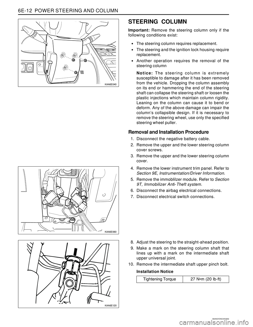
Removal and Installation Procedure
1. Disconnect the negative battery cable.
2. Remove the upper and the lower steering column
cover screws.
3. Remove the upper and the lower steering column
cover.
KAA6E060
4. Remove the lower instrument trim panel. Refer to
Section 9E, Instrumentation/Driver Information.
5. Remove the immoblilzer module. Refer to Section
9T, Immobilizer Anti-Theft system.
6. Disconnect the airbag electrical connections.
7. Disconnect electrical switch connections.
8. Adjust the steering to the straight-ahead position.
9. Make a mark on the steering column shaft that
lines up with a mark on the intermediate shaft
upper universal joint.
10. Remove the intermediate shaft upper pinch bolt.
Installation Notice
Tightening Torque 27 Nm (20 lb-ft)
Page 1642 of 2053

SSANGYONG MY2002
8B-60 SUPPLEMENTAL RESTRAINTS SYSTEM
KAA8B140
DRIVER AIRBAG MODULE
Removal and installation Procedure
1. Disconnect the negative battery cable.
Caution: The SDM can maintain sufficient
voltage to deploy the airbags for 0.15 seconds
after the Ignition is OFF and the airbag fuse has
been removed. If the airbags are not
disconnected, service cannot begin until one
minute has passed after disconnecting power
to the SDM. If the airbags are disconnected,
service can begin immediately without waiting
for one-minute time period to expire. Failure to
temporarily disable the SRS during service
result in unexpected deployment, personal
injury, and otherwise unneeded SRS repair.
2. Disable the supplemental restraint system (SRS).
Refer to “Disabling the SRS” in this section.
3. Position the steering wheel straight ahead.
4. Remove the driver airbag module mounting bolts.
Installation Notice
Caution: When handling an airbag module,
always keeps the top of the unit facing upward.
This leaves room for the airbag to expand if the
module unexpectedly deploys. Without room
for expansion, a module suddenly propelled
toward a person or object can cause injury or
vehicle damage.
5. Remove the connector from the horn terminal and
the driver airbag module.
6. Remove the driver airbag module.
7. Installation should follow the removal procedure
in the reverse order.
Tightening Torque 8 Nm (71 lb-in)