Page 1387 of 2053
TRANSFER CASE 5D1-17
SSANGYONG MY2002
Step
3
4
5
6
7ActionYes
Go to Step 4
System OK
Go to Step 6
System OK
System OKNo
Go to Step 5
-
System OK
Go to Step-7
- Value(s)
1. Turn the ignition switch to ON.
2. Set the shift lever to N (neutral).
3. Turn the 4H/4L switch to 4L.
Does the 4WD LOWindicator go off?
The wiring of 4H/4L switch is reversed. Repair the
wiring.
Is the repair complete?
1. Turn the ignition OFF.
2. Check the pin or terminals for damage or improper
connection.
3. Reconnect all the connectors.
4. Turn the ignition ON.
Does the 4WD LOW indicator come on steadily?
Repair any short to ground circuit between terminal B9
of TCCU connector and terminal A8 of cluster.
Is the repair complete?
Replace the TCCU.
Is the repair complete?
Page 1389 of 2053

TRANSFER CASE 5D1-67
SSANGYONG MY2002
KAA5D260
KAA5D270
TRANSFER CASE CONTROL UNIT
(TCCU)
Removal and Installation Procedure
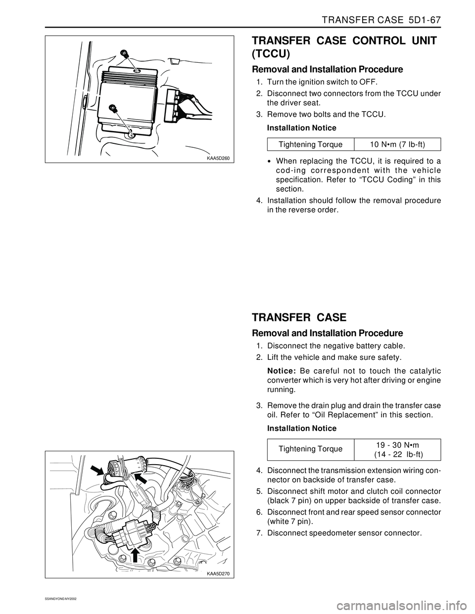
1. Turn the ignition switch to OFF.
2. Disconnect two connectors from the TCCU under
the driver seat.
3. Remove two bolts and the TCCU.
Installation Notice
Tightening Torque 10 Nm (7 lb-ft)
When replacing the TCCU, it is required to a
cod-ing correspondent with the vehicle
specification. Refer to “TCCU Coding” in this
section.
4. Installation should follow the removal procedure
in the reverse order.
TRANSFER CASE
Removal and Installation Procedure
1. Disconnect the negative battery cable.
2. Lift the vehicle and make sure safety.
Notice: Be careful not to touch the catalytic
converter which is very hot after driving or engine
running.
3. Remove the drain plug and drain the transfer case
oil. Refer to “Oil Replacement” in this section.
Installation Notice
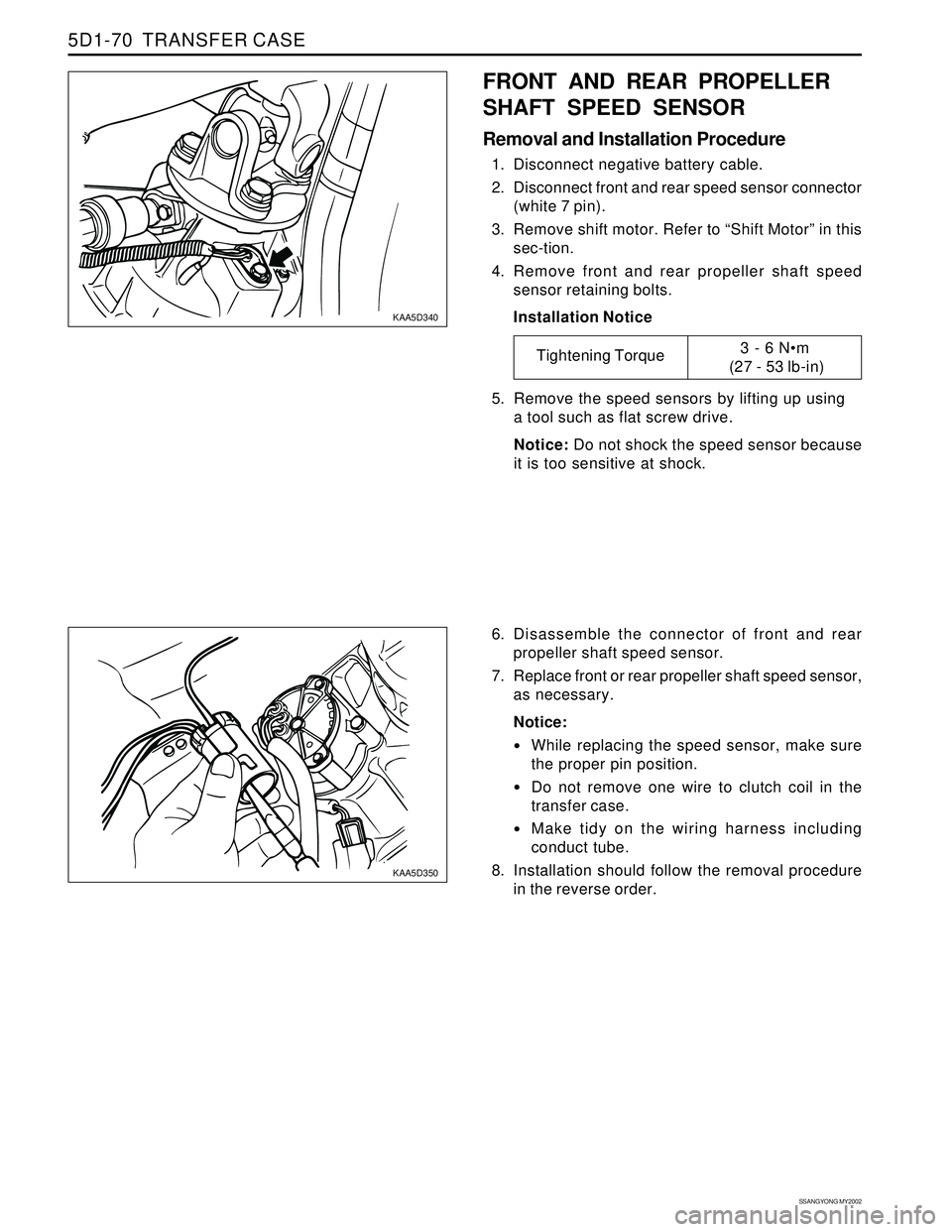
4. Disconnect the transmission extension wiring con-
nector on backside of transfer case.
5. Disconnect shift motor and clutch coil connector
(black 7 pin) on upper backside of transfer case.
6. Disconnect front and rear speed sensor connector
(white 7 pin).
7. Disconnect speedometer sensor connector.
Tightening Torque19 - 30 Nm
(14 - 22 lb-ft)
Page 1392 of 2053

SSANGYONG MY2002
5D1-70 TRANSFER CASE
KAA5D340
KAA5D350
FRONT AND REAR PROPELLER
SHAFT SPEED SENSOR
Removal and Installation Procedure
1. Disconnect negative battery cable.
2. Disconnect front and rear speed sensor connector
(white 7 pin).
3. Remove shift motor. Refer to “Shift Motor” in this
sec-tion.
4. Remove front and rear propeller shaft speed
sensor retaining bolts.
Installation Notice
6. Disassemble the connector of front and rear
propeller shaft speed sensor.
7. Replace front or rear propeller shaft speed sensor,
as necessary.
Notice:
While replacing the speed sensor, make sure
the proper pin position.
Do not remove one wire to clutch coil in the
transfer case.
Make tidy on the wiring harness including
conduct tube.
8. Installation should follow the removal procedure
in the reverse order. 5. Remove the speed sensors by lifting up using
a tool such as flat screw drive.
Notice: Do not shock the speed sensor because
it is too sensitive at shock.
Tightening Torque3 - 6 Nm
(27 - 53 lb-in)
Page 1410 of 2053

SSANGYONG MY2002
5D2-10 TRANSFER CASE (PART TIME - 4408)
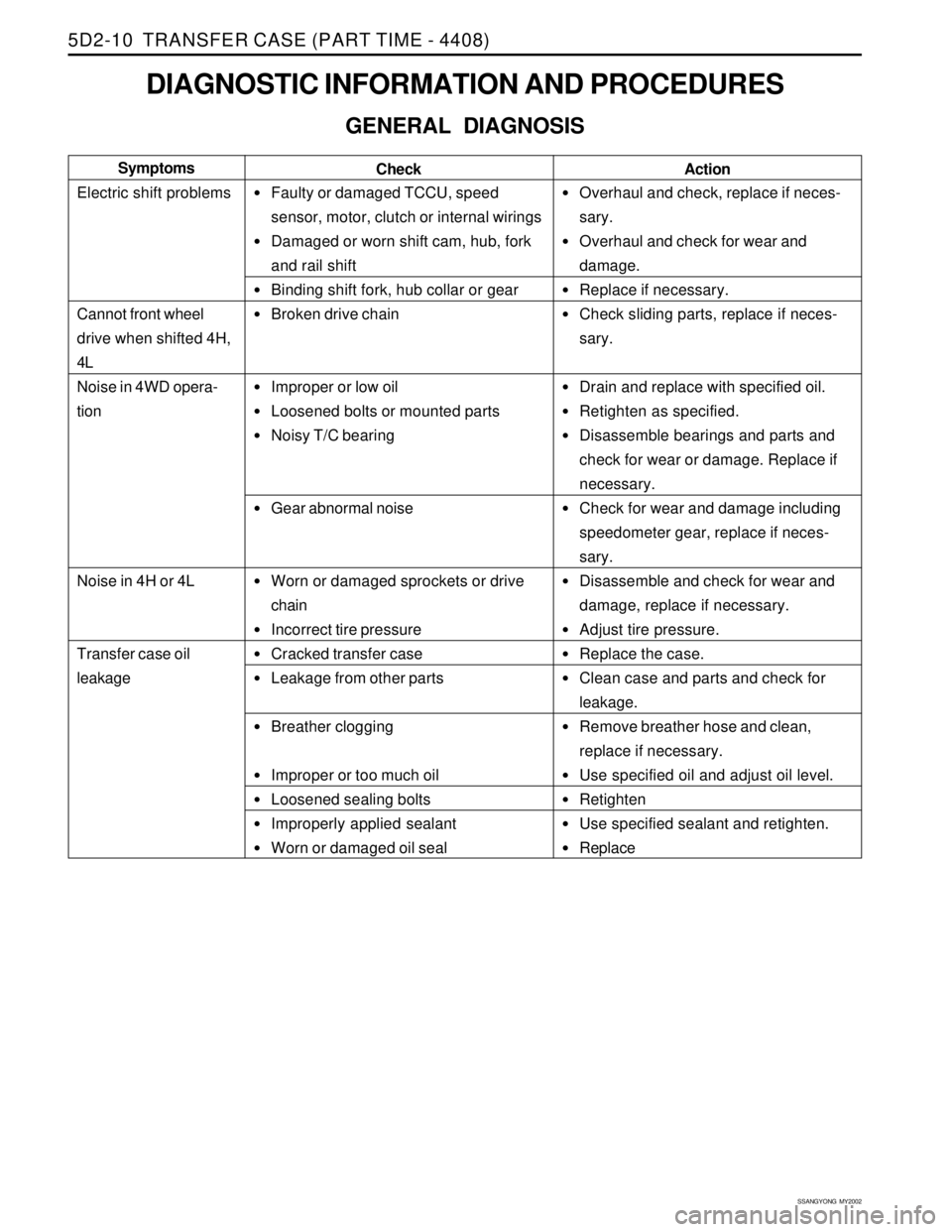
DIAGNOSTIC INFORMATION AND PROCEDURES
GENERAL DIAGNOSIS
Faulty or damaged TCCU, speed
sensor, motor, clutch or internal wirings
Damaged or worn shift cam, hub, fork
and rail shift
Binding shift fork, hub collar or gear
Broken drive chain
Improper or low oil
Loosened bolts or mounted parts
Noisy T/C bearing
Gear abnormal noise
Worn or damaged sprockets or drive
chain
Incorrect tire pressure
Cracked transfer case
Leakage from other parts
Breather clogging
Improper or too much oil
Loosened sealing bolts
Improperly applied sealant
Worn or damaged oil seal
Overhaul and check, replace if neces-
sary.
Overhaul and check for wear and
damage.
Replace if necessary.
Check sliding parts, replace if neces-
sary.
Drain and replace with specified oil.
Retighten as specified.
Disassemble bearings and parts and
check for wear or damage. Replace if
necessary.
Check for wear and damage including
speedometer gear, replace if neces-
sary.
Disassemble and check for wear and
damage, replace if necessary.
Adjust tire pressure.
Replace the case.
Clean case and parts and check for
leakage.
Remove breather hose and clean,
replace if necessary.
Use specified oil and adjust oil level.
Retighten
Use specified sealant and retighten.
Replace Check Symptoms
Electric shift problems
Cannot front wheel
drive when shifted 4H,
4L
Noise in 4WD opera-
tion
Noise in 4H or 4L
Transfer case oil
leakage
Action
Page 1420 of 2053

TRANSFER CASE (PART TIME - 4408) 5D2-21
SSANGYONG MY2002
KAA5D240
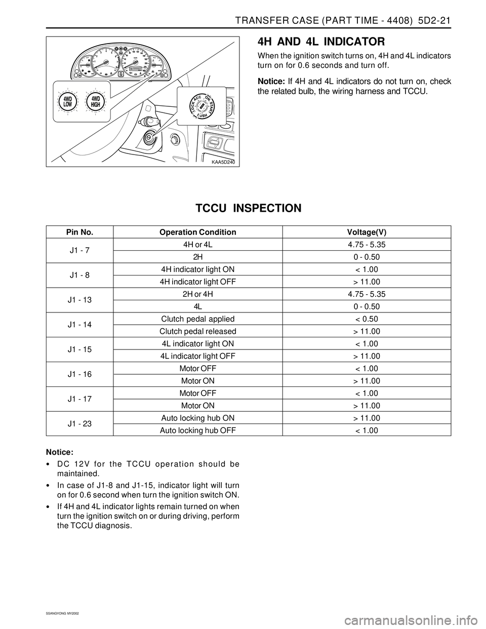
4H AND 4L INDICATOR
When the ignition switch turns on, 4H and 4L indicators
turn on for 0.6 seconds and turn off.
Notice: If 4H and 4L indicators do not turn on, check
the related bulb, the wiring harness and TCCU.
J1 - 7
J1 - 8
J1 - 13
J1 - 14
J1 - 15
J1 - 16
J1 - 17
J1 - 234H or 4L
2H
4H indicator light ON
4H indicator light OFF
2H or 4H
4L
Clutch pedal applied
Clutch pedal released
4L indicator light ON
4L indicator light OFF
Motor OFF
Motor ON
Motor OFF
Motor ON
Auto locking hub ON
Auto locking hub OFF
TCCU INSPECTION
4.75 - 5.35
0 - 0.50
< 1.00
> 11.00
4.75 - 5.35
0 - 0.50
< 0.50
> 11.00
< 1.00
> 11.00
< 1.00
> 11.00
< 1.00
> 11.00
> 11.00
< 1.00
Pin No. Voltage(V)Operation Condition
Notice:
DC 12V for the TCCU operation should be
maintained.
In case of J1-8 and J1-15, indicator light will turn
on for 0.6 second when turn the ignition switch ON.
If 4H and 4L indicator lights remain turned on when
turn the ignition switch on or during driving, perform
the TCCU diagnosis.
Page 1421 of 2053
SSANGYONG MY2002
5D2-22 TRANSFER CASE (PART TIME - 4408)
KAA5D270
KAA5D280
TRANSFER CASE ASSEMBLY
1. Disconnect the negative terminal from the battery.
2. Lift up the vehicle and fix it safely.
3. Remove the damper mounting bolt.
4. Remove the drain plug and drain the oil.
Reinstall the drain plug.
Installation Notice
KAA5D290
5. Remove the breather hose.
6. Disconnect the speedometer cable connector and
other cable connectors and wiring harnesses.20 - 30 Nm
(15 - 22 lb-ft)
30 - 40 Nm
(22 - 30 lb-ft)
4 - 6 Nm
(35 - 53 lb-in)
Drain Plug Tightening
Torque
Damper Tightening
Torque
Fill plug Tightening
Torque
Page 1424 of 2053
SSANGYONG MY2002
5D2-26 TRANSFER CASE (PART TIME - 4408)
KAA5D420
KAA5D430
3. Remove the clutch coil wiring from the connector.
4. Remove the clutch coil assembly mounting nut.
KAA5D440
KAA5D450
5. Remove the snap ring and pull out the ball bearing
from the cover to remove the speed gear.
6. Remove the clutch coil assembly and the oil seal
from the cover.
7. Remove the speed sensor and the O-ring from
the case cover.
Page 1441 of 2053
SSANGYONG MY2002
5D2-42 TRANSFER CASE (PART TIME - 4408)
5. Tighten 9 bolts positioning identification tag and
wiring clip.
Installation Notice
6. Install the speed gear over output shaft spline in
the cover assembly.
7. Press the new oil seal into the cover assembly.
Tightening Torque28 - 40 Nm
(21 - 30 lb-ft)
KAA5D920
KAA5D930
KAA5D940
External Electric Shift
1. Align the motor with shift shaft and position the
motor assembly onto the cover.
2. Install the motor to the shift shaft and contact
cover and rotate the motor clockwise direction to
check correct engagement.
3. Insert the O-ring on the speed sensor assembly
to the cover.
4. Install the bracket to the motor assembly and
tighten 3 bolts.
Installation Notice
Tightening Torque8 - 11 Nm
(71 - 97 lb-in)