Page 1252 of 2053
5A-154 AUTOMATIC TRANSMISSION
SSANGYONG MY2002
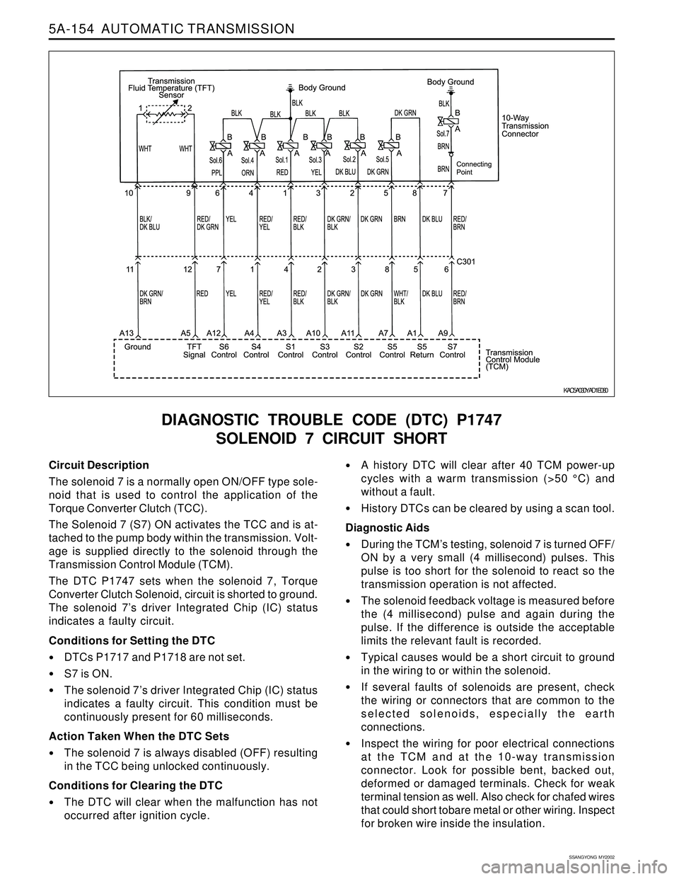
DIAGNOSTIC TROUBLE CODE (DTC) P1747
SOLENOID 7 CIRCUIT SHORT
Circuit Description
The solenoid 7 is a normally open ON/OFF type sole-
noid that is used to control the application of the
Torque Converter Clutch (TCC).
The Solenoid 7 (S7) ON activates the TCC and is at-
tached to the pump body within the transmission. Volt-
age is supplied directly to the solenoid through the
Transmission Control Module (TCM).
The DTC P1747 sets when the solenoid 7, Torque
Converter Clutch Solenoid, circuit is shorted to ground.
The solenoid 7’s driver Integrated Chip (IC) status
indicates a faulty circuit.
Conditions for Setting the DTC
DTCs P1717 and P1718 are not set.
S7 is ON.
The solenoid 7’s driver Integrated Chip (IC) status
indicates a faulty circuit. This condition must be
continuously present for 60 milliseconds.
Action Taken When the DTC Sets
The solenoid 7 is always disabled (OFF) resulting
in the TCC being unlocked continuously.
Conditions for Clearing the DTC
The DTC will clear when the malfunction has not
occurred after ignition cycle.
A history DTC will clear after 40 TCM power-up
cycles with a warm transmission (>50 °C) and
without a fault.
History DTCs can be cleared by using a scan tool.
Diagnostic Aids
During the TCM’s testing, solenoid 7 is turned OFF/
ON by a very small (4 millisecond) pulses. This
pulse is too short for the solenoid to react so the
transmission operation is not affected.
The solenoid feedback voltage is measured before
the (4 millisecond) pulse and again during the
pulse. If the difference is outside the acceptable
limits the relevant fault is recorded.
Typical causes would be a short circuit to ground
in the wiring to or within the solenoid.
If several faults of solenoids are present, check
the wiring or connectors that are common to the
selected solenoids, especially the earth
connections.
Inspect the wiring for poor electrical connections
at the TCM and at the 10-way transmission
connector. Look for possible bent, backed out,
deformed or damaged terminals. Check for weak
terminal tension as well. Also check for chafed wires
that could short tobare metal or other wiring. Inspect
for broken wire inside the insulation.
KAC5A030YAD1E080
Page 1253 of 2053
AUTOMATIC TRANSMISSION 5A-155
SSANGYONG MY2002
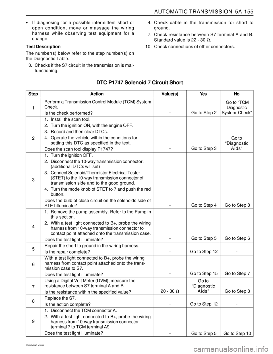
DTC P1747 Solenoid 7 Circuit Short
If diagnosing for a possible intermittent short or
open condition, move or massage the wiring
harness while observing test equipment for a
change.
Test Description
The number(s) below refer to the step number(s) on
the Diagnostic Table.
3. Checks if the S7 circuit in the transmission is mal-
functioning.4. Check cable in the transmission for short to
ground.
7. Check resistance between S7 terminal A and B.
Standard value is 22 - 30 Ω.
10. Check connections of other connectors.
- Go to Step 15 Go to Step 7 1Perform a Transmission Control Module (TCM) System
Check.
Is the check performed?
1. Install the scan tool.
2. Turn the ignition ON, with the engine OFF.
3. Record and then clear DTCs.
4. Operate the vehicle within the conditions for
setting this DTC as specified in the text.
Does the scan tool display P1747?
1. Turn the ignition OFF.
2. Disconnect the 10-way transmission connector.
(additional DTCs will set)
3. Connect Solenoid/Thermistor Electrical Tester
(STET) to the 10-way transmission connector of
transmission side and to the good ground.
4. Turn the mode knob of STET to 7 and push the red
button.
Does the bulb of close circuit on the solenoids side of
STET illuminate?
1. Remove the pump assembly. Refer to the Pump in
this section.
2. With a test light connected to B+, probe the wiring
harness from 10-way transmission connector to
contact point attached onto the transmission case.
Does the test light illuminate?
Repair the short to ground in the wiring harness.
Is the repair complete?
With a test light connected to B+, probe the wiring
harness from contact point attached onto the trans-
mission case to S7.
Does the test light illuminate?
Using a Digital Volt Meter (DVM), measure the
resistance between S7 terminal A and B.
Is the resistance within the specified value?
Replace the S7.
Is the action complete?
1. Disconnect the TCM connector A.
2. With a test light connected to B+, probe the wiring
harness from 10-way transmission connector
terminal 7 to TCM terminal A9.
Does the test light illuminate?
StepAction Value(s) Yes No
2
3
-
Go to Step 2 Go to “TCM
Diagnostic
System Check”
- Go to Step 4 Go to Step 8
5
6 4
- Go to Step 5 Go to Step 6
- Go to Step 12 -
7
8
9
- Go to Step 12 -
- Go to Step 5 Go to Step 10
- Go to Step 3Go to
“Diagnostic
Aids”
20 - 30 ΩGo to
“Diagnostic
Aids”
Go to Step 8
Page 1256 of 2053
AUTOMATIC TRANSMISSION 5A-161
SSANGYONG MY2002
DISASSEMBLY PROCEDURE
Transmission
Tools Required
0555-336256Transmission Bench Cradle
0555-336257Pump Puller
Notice:
Remove the inhibitor switch before washing the
transmission in solvent or hot wash.
It is assumed that the transmission fluid has been
drained when the transmission was removed from
the vehicle and that the ‘special tools’ quoted are
available.
The transmission is dismantled in a modular fashion,
and the details of disassembly for each module are
given under the appropriate subject. Refer to Special
Tools Table in this chapter for details of all special
tools required when performing disassembly
procedures.
Technicians overhauling these transmissions will
also require a selection of good quality Torx bit
sockets, in particular numbers 30, 40 and 50, and
an 8 mm, 10 mm and 12 mm double hex socket.
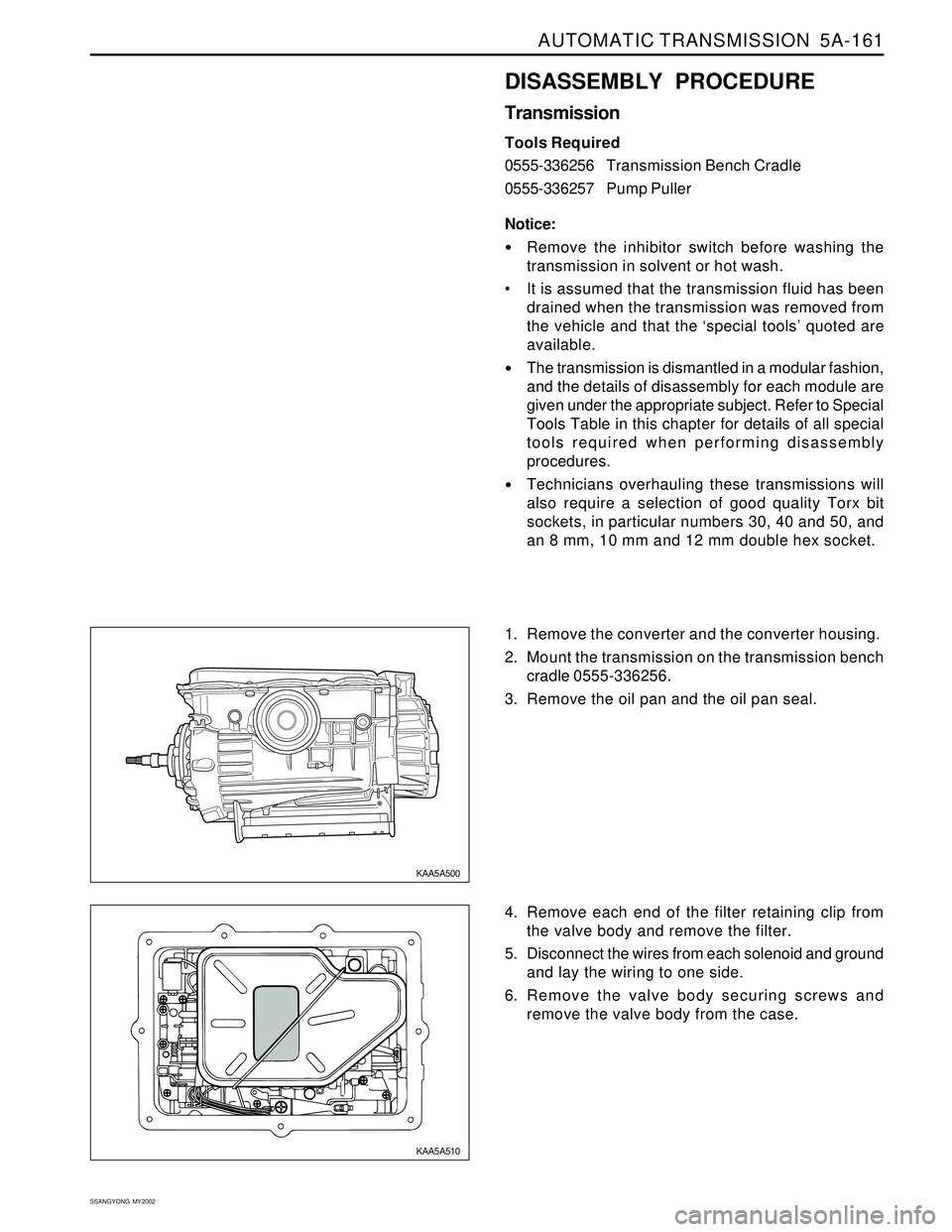
1. Remove the converter and the converter housing.
2. Mount the transmission on the transmission bench
cradle 0555-336256.
3. Remove the oil pan and the oil pan seal.
4. Remove each end of the filter retaining clip from
the valve body and remove the filter.
5. Disconnect the wires from each solenoid and ground
and lay the wiring to one side.
6. Remove the valve body securing screws and
remove the valve body from the case.
KAA5A500
KAA5A510
Page 1259 of 2053
5A-164 AUTOMATIC TRANSMISSION
SSANGYONG MY2002
5. Using cross shaft pin remover/installer (detent le-
ver) 0555-336258, press the pin from the cross
shaft and withdraw the shaft from the case.
6. Remove the cross shaft pin and spring.
7. Remove the manual valve lever and the park rod.
8. Depress the tangs and withdraw the 10 pin
connector into the case. Remove the wiring loom
assembly.
9. Detach the No. 7 solenoid wire from the front of
the case.
10. Remove the parking pawl pivot pin and the pawl
and spring from the case.
11. Remove the shaft and the rear servo lever.
12. Remove the rear servo cover and piston assembly.
13. Remove the B1R circlip, valve and spring.
14. Remove both band adjustment shims.
15. Inspect the output shaft bushing in the case and
replace if necessary.
16. Inspect cooler line fittings and replace as
necessary.
17. Inspect the case for damage.
KAA5A600
KAA5A610
KAA5A620
KAA5A630
Page 1263 of 2053
5A-168 AUTOMATIC TRANSMISSION
SSANGYONG MY2002
Pump
Notice: The following valves are housed in the pump
cover:
Solenoid 7
Converter clutch control valve
Converter clutch regulator valve
Primary regulator valve
1. Remove the wiring loom retainer plate and remove
solenoid 7 with a T30 Torx bit.
2. Remove the five washer head bolts from the cover
plate using a multi-point 8 mm socket.
3. Remove the five Torx head screws from the cover
plate with T30 Torx bit. Note that the long screw
holds the pump body to the pump body cover.
Notice: Do not strike the converter support tube to
loosen the pump body.
4. Separate the pump body from the pump cover.
5. Remove the cover plate, gasket and seal from the
cover.
6. Remove the ball check valve and one spring from
the pump cover.
KAA5A790 KAA5A780 KAA5A770
Page 1268 of 2053
AUTOMATIC TRANSMISSION 5A-173
SSANGYONG MY2002
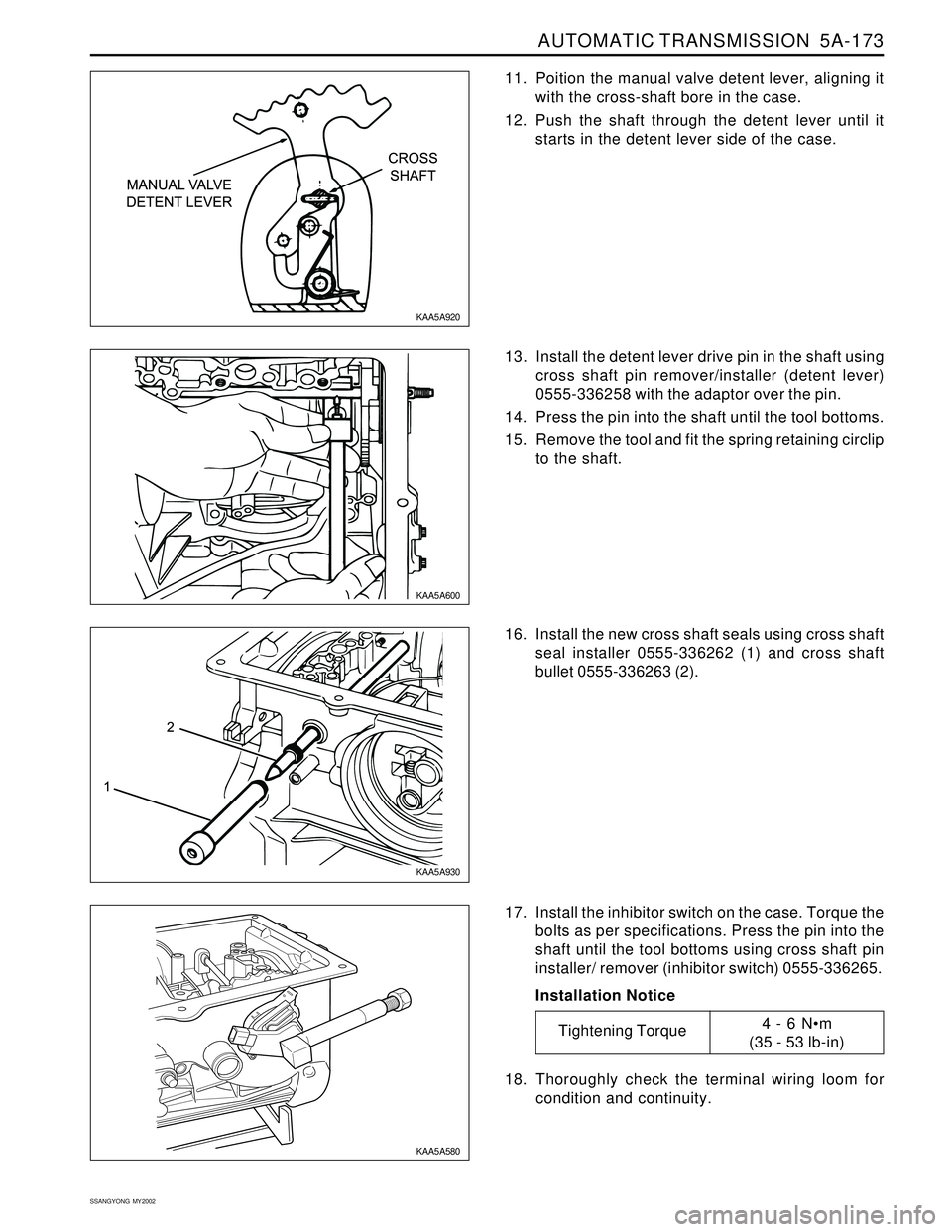
11. Poition the manual valve detent lever, aligning it
with the cross-shaft bore in the case.
12. Push the shaft through the detent lever until it
starts in the detent lever side of the case.
16. Install the new cross shaft seals using cross shaft
seal installer 0555-336262 (1) and cross shaft
bullet 0555-336263 (2).
17. Install the inhibitor switch on the case. Torque the
bolts as per specifications. Press the pin into the
shaft until the tool bottoms using cross shaft pin
installer/ remover (inhibitor switch) 0555-336265.
Installation Notice
18. Thoroughly check the terminal wiring loom for
condition and continuity. 13. Install the detent lever drive pin in the shaft using
cross shaft pin remover/installer (detent lever)
0555-336258 with the adaptor over the pin.
14. Press the pin into the shaft until the tool bottoms.
15. Remove the tool and fit the spring retaining circlip
to the shaft.
KAA5A920
KAA5A600
KAA5A930
KAA5A580
Tightening Torque4 - 6 Nm
(35 - 53 lb-in)
Page 1269 of 2053
5A-174 AUTOMATIC TRANSMISSION
SSANGYONG MY2002
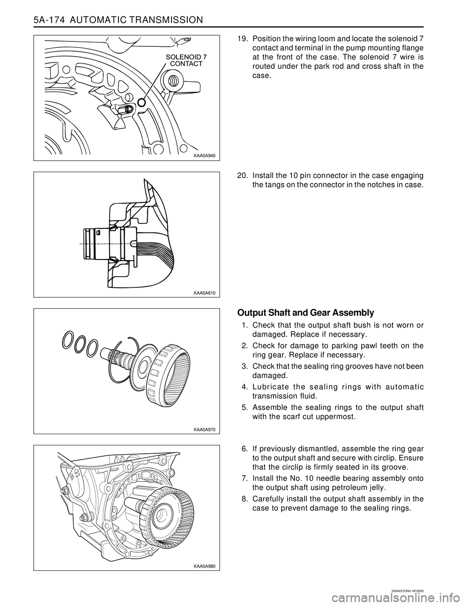
19. Position the wiring loom and locate the solenoid 7
contact and terminal in the pump mounting flange
at the front of the case. The solenoid 7 wire is
routed under the park rod and cross shaft in the
case.
20. Install the 10 pin connector in the case engaging
the tangs on the connector in the notches in case.
Output Shaft and Gear Assembly
1. Check that the output shaft bush is not worn or
damaged. Replace if necessary.
2. Check for damage to parking pawl teeth on the
ring gear. Replace if necessary.
3. Check that the sealing ring grooves have not been
damaged.
4. Lubricate the sealing rings with automatic
transmission fluid.
5. Assemble the sealing rings to the output shaft
with the scarf cut uppermost.
6. If previously dismantled, assemble the ring gear
to the output shaft and secure with circlip. Ensure
that the circlip is firmly seated in its groove.
7. Install the No. 10 needle bearing assembly onto
the output shaft using petroleum jelly.
8. Carefully install the output shaft assembly in the
case to prevent damage to the sealing rings.
KAA5A940
KAA5A610
KAA5A970
KAA5A980
Page 1285 of 2053
5A-190 AUTOMATIC TRANSMISSION
SSANGYONG MY2002
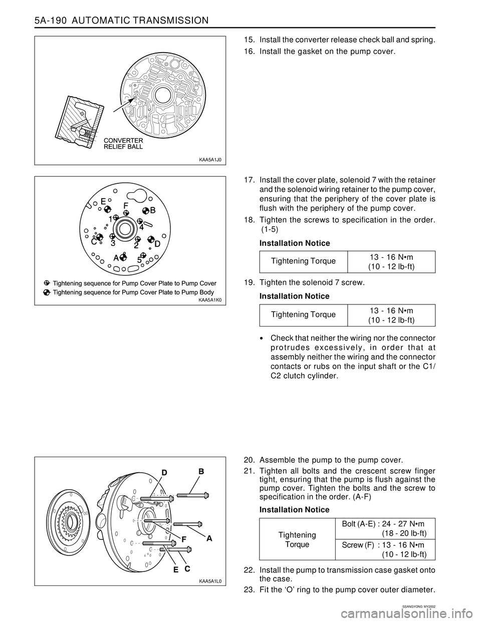
15. Install the converter release check ball and spring.
16. Install the gasket on the pump cover.
17. Install the cover plate, solenoid 7 with the retainer
and the solenoid wiring retainer to the pump cover,
ensuring that the periphery of the cover plate is
flush with the periphery of the pump cover.
18. Tighten the screws to specification in the order.
(1-5)
Installation Notice
20. Assemble the pump to the pump cover.
21. Tighten all bolts and the crescent screw finger
tight, ensuring that the pump is flush against the
pump cover. Tighten the bolts and the screw to
specification in the order. (A-F)
Installation Notice 19. Tighten the solenoid 7 screw.
Installation Notice
Check that neither the wiring nor the connector
protrudes excessively, in order that at
assembly neither the wiring and the connector
contacts or rubs on the input shaft or the C1/
C2 clutch cylinder.
22. Install the pump to transmission case gasket onto
the case.
23. Fit the ‘O’ ring to the pump cover outer diameter.
KAA5A1J0
KAA5A1K0
KAA5A1L0
Tightening Torque13 - 16 Nm
(10 - 12 lb-ft)
Tightening Torque13 - 16 Nm
(10 - 12 lb-ft)
Tightening
TorqueBolt (A-E) : 24 - 27 Nm
(18 - 20 lb-ft)
Screw (F) : 13 - 16 Nm
(10 - 12 lb-ft)