1997 SSANGYONG KORANDO wiring
[x] Cancel search: wiringPage 1502 of 2053
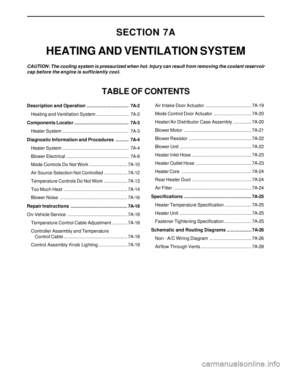
SECTION 7A
HEATING AND VENTILATION SYSTEM
CAUTION: The cooling system is pressurized when hot. Injury can result from removing the coolant reservoir
cap before the engine is sufficiently cool.
TABLE OF CONTENTS
Description and Operation ................................7A-2
Heating and Ventilation System .........................7A-2
Components Locator ..........................................7A-3
Heater System ...................................................7A-3
Diagnostic Information and Procedures ..........7A-4
Heater System ...................................................7A-4
Blower Electrical ................................................7A-8
Mode Controls Do Not Work .............................7A-10
Air Source Selection Not Controlled ..................7A-12
Temperature Controls Do Not Work ..................7A-13
Too Much Heat .................................................7A-14
Blower Noise ....................................................7A-16
Repair Instructions ............................................7A-18
On-Vehicle Service..............................................7A-18
Temperature Control Cable Adjustment ............7A-18
Controller Assembly and Temperature
Control Cable .................................................7A-18
Control Assembly Knob Lighting ......................7A-19Air Intake Door Actuator ...................................7A-19
Mode Control Door Actuator .............................7A-20
Heater/Air Distributor Case Assembly ..............7A-20
Blower Motor ....................................................7A-21
Blower Resistor ................................................7A-22
Blower Unit .......................................................7A-22
Heater Inlet Hose ..............................................7A-23
Heater Outlet Hose ...........................................7A-23
Heater Core......................................................7A-24
Rear Heater Duct ..............................................7A-24
Air Filter ............................................................7A-24
Specifications .................................................... 7A-25
Heater Temperature Specification .....................7A-25
Heater Unit .......................................................7A-25
Fastener Tightening Specification .....................7A-25
Schematic and Routing Diagrams ................... 7A-26
Non - A/C Wiring Diagram ................................7A-26
Airflow Through Vents .......................................7A-28
Page 1514 of 2053
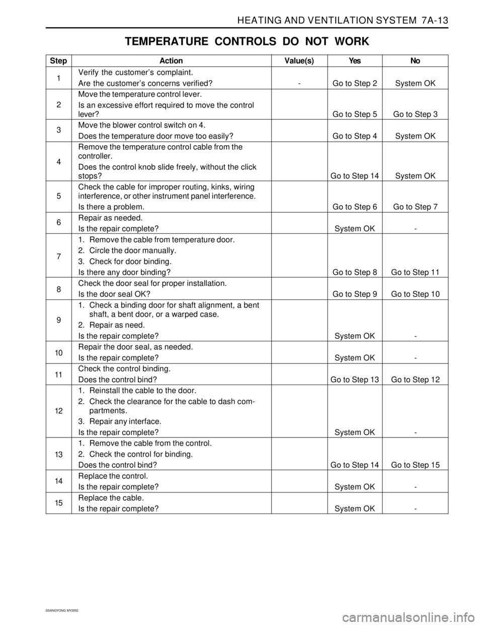
HEATING AND VENTILATION SYSTEM 7A-13
SSANGYONG MY2002
TEMPERATURE CONTROLS DO NOT WORK
Step
1
2
3
4
5
6
7
8
9
10
11
12
13
14
15Action
Verify the customer’s complaint.
Are the customer’s concerns verified?
Move the temperature control lever.
Is an excessive effort required to move the control
lever?
Move the blower control switch on 4.
Does the temperature door move too easily?
Remove the temperature control cable from the
controller.
Does the control knob slide freely, without the click
stops?
Check the cable for improper routing, kinks, wiring
interference, or other instrument panel interference.
Is there a problem.
Repair as needed.
Is the repair complete?
1. Remove the cable from temperature door.
2. Circle the door manually.
3. Check for door binding.
Is there any door binding?
Check the door seal for proper installation.
Is the door seal OK?
1. Check a binding door for shaft alignment, a bent
shaft, a bent door, or a warped case.
2. Repair as need.
Is the repair complete?
Repair the door seal, as needed.
Is the repair complete?
Check the control binding.
Does the control bind?
1. Reinstall the cable to the door.
2. Check the clearance for the cable to dash com-
partments.
3. Repair any interface.
Is the repair complete?
1. Remove the cable from the control.
2. Check the control for binding.
Does the control bind?
Replace the control.
Is the repair complete?
Replace the cable.
Is the repair complete?Yes
Go to Step 2
Go to Step 5
Go to Step 4
Go to Step 14
Go to Step 6
System OK
Go to Step 8
Go to Step 9
System OK
System OK
Go to Step 13
System OK
Go to Step 14
System OK
System OKNo
System OK
Go to Step 3
System OK
System OK
Go to Step 7
-
Go to Step 11
Go to Step 10
-
-
Go to Step 12
-
Go to Step 15
-
-Value(s)
-
Page 1527 of 2053
SSANGYONG MY2002
7A-26 HEATING AND VENTILATION SYSTEM
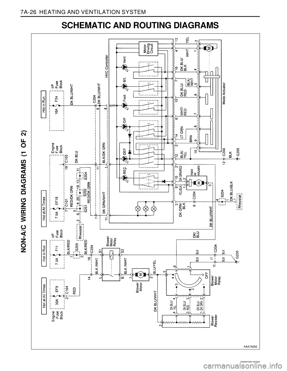
NON-A/C WIRING DIAGRAMS (1 OF 2)
SCHEMATIC AND ROUTING DIAGRAMS
KAA7A200
Page 1528 of 2053
HEATING AND VENTILATION SYSTEM 7A-27
SSANGYONG MY2002
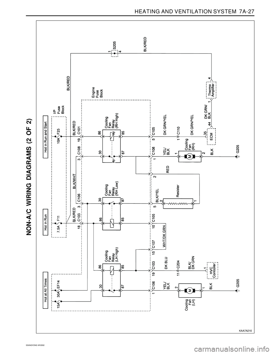
NON-A/C WIRING DIAGRAMS (2 OF 2)
KAA7A210
Page 1534 of 2053
MANUAL & SEMIAUTO-HVAC 7C-5
SSANGYONG MY2002
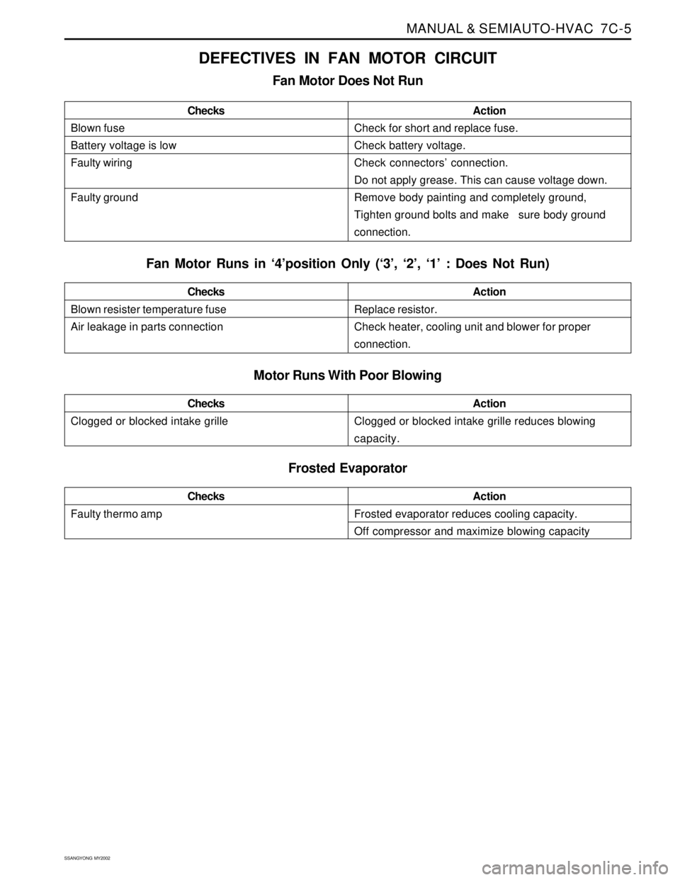
DEFECTIVES IN FAN MOTOR CIRCUIT
Fan Motor Does Not Run
Blown fuse
Battery voltage is low
Faulty wiring
Faulty groundChecksActionCheck for short and replace fuse.
Check battery voltage.
Check connectors’ connection.
Do not apply grease. This can cause voltage down.
Remove body painting and completely ground,
Tighten ground bolts and make sure body ground
connection.
Fan Motor Runs in ‘4’position Only (‘3’, ‘2’, ‘1’ : Does Not Run)
Motor Runs With Poor Blowing
Blown resister temperature fuse
Air leakage in parts connectionChecksActionReplace resistor.
Check heater, cooling unit and blower for proper
connection.
Clogged or blocked intake grilleChecksActionClogged or blocked intake grille reduces blowing
capacity.
Frosted Evaporator
Faulty thermo ampChecksActionFrosted evaporator reduces cooling capacity.
Off compressor and maximize blowing capacity
Page 1575 of 2053
FATC-HAVC 7D-21
SSANGYONG MY2002
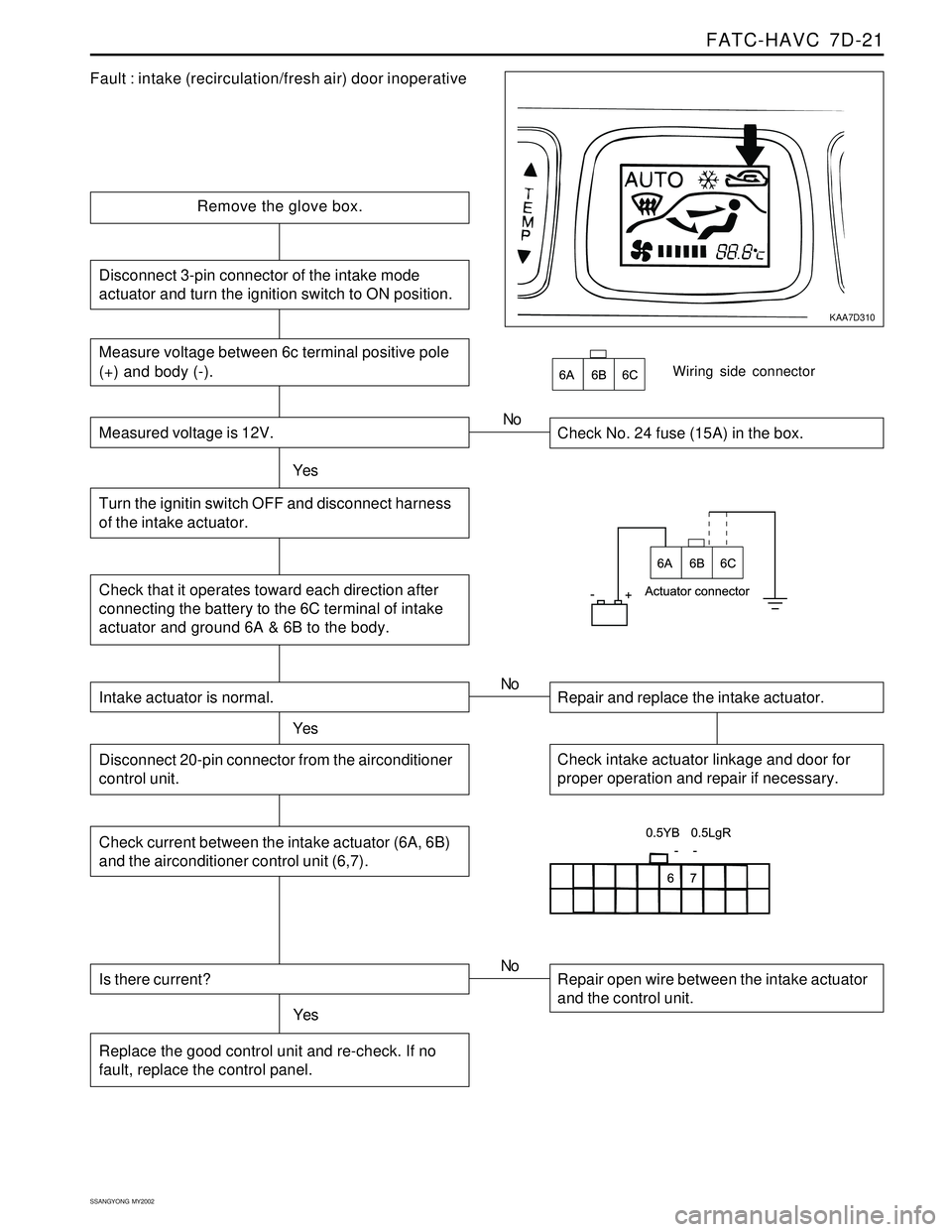
KAA7D310
Fault : intake (recirculation/fresh air) door inoperative
Remove the glove box.
Check No. 24 fuse (15A) in the box.
YesNo
Check that it operates toward each direction after
connecting the battery to the 6C terminal of intake
actuator and ground 6A & 6B to the body.
Wiring side connector
Intake actuator is normal.
YesRepair and replace the intake actuator. No
Check intake actuator linkage and door for
proper operation and repair if necessary.Disconnect 20-pin connector from the airconditioner
control unit.
Check current between the intake actuator (6A, 6B)
and the airconditioner control unit (6,7).
Is there current?
YesRepair open wire between the intake actuator
and the control unit. No
Replace the good control unit and re-check. If no
fault, replace the control panel.
Measure voltage between 6c terminal positive pole
(+) and body (-).
Measured voltage is 12V.
Turn the ignitin switch OFF and disconnect harness
of the intake actuator.
Disconnect 3-pin connector of the intake mode
actuator and turn the ignition switch to ON position.
Page 1586 of 2053
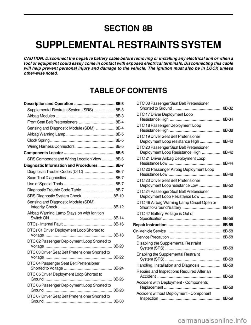
SECTION 8B
SUPPLEMENTAL RESTRAINTS SYSTEM
CAUTION: Disconnect the negative battery cable before removing or installing any electrical unit or when a
tool or equipment could easily come in contact with exposed electrical terminals. Disconnecting this cable
will help prevent personal injury and damage to the vehicle. The ignition must also be in LOCK unless
other-wise noted.
TABLE OF CONTENTS
Description and Operation...................................8B-3
Supplemental Restraint System (SRS)..................8B-3
Airbag Modules...................................................8B-3
Front Seat Belt Pretensioners...............................8B-4
Sensing and Diagnostic Module (SDM)................8B-4
Airbag Warning Lamp ..........................................8B-5
Clock Spring........................................................8B-5
Wiring Harness Connectors..................................8B-5
Components Locator............................................8B-6
SRS Component and Wiring Location View...........8B-6
Diagnostic Information and Procedures..............8B-7
Diagnostic Trouble Codes (DTC)..........................8B-7
Scan Tool Diagnostics.........................................8B-7
Use of Special Tools............................................8B-7
Diagnostic Trouble Code Table............................8B-7
SRS Diagnostic System Check..........................8B-10
Sensing and Diagnostic Module (SDM)
Integrity Check...............................................8B-12
Airbag Warning Lamp Stays on with Ignition
Switch ON......................................................8B-14
DTCs - Internal Fault..........................................8B-16
DTCs 01 Driver Deployment Loop Shorted to
Voltage...........................................................8B-18
DTC 02 Passenger Deployment Loop Shorted to
Voltage...........................................................8B-20
DTC 03 Driver Seat Belt Pretensioner Shorted to
Voltage...........................................................8B-22
DTC 04 Passenger Seat Belt Pretensioner
Shorted to Voltage..........................................8B-24
DTC 05 Driver Deployment Loop Shorted to
Ground...........................................................8B-26
DTC 06 Passenger Deployment Loop Shorted to
Ground...........................................................8B-28
DTC 07 Driver Seat Belt Pretensioner Shorted to
Ground...........................................................8B-30DTC 08 Passenger Seat Belt Pretensioner
Shorted to Ground ..........................................8B-32
DTC 17 Driver Deployment Loop
Resistance High.............................................8B-34
DTC 18 Passenger Deployment Loop
Resistance High.............................................8B-38
DTC 19 Driver Seat Belt Pretensioner
Deployment Loop resistance High...................8B-40
DTC 20 Passenger Seat Belt Pretensioner
Deployment Loop Resistance High.................8B-42
DTC 21 Driver Airbag Deployment Loop
Resistance Low..............................................8B-44
DTC 22 Passenger Airbag Deployment Loop
Resistance Low..............................................8B-48
DTC 23 Driver Seat Belt Pretensioner
Deployment Loop resistance Low....................8B-50
DTC 24 Passenger Seat Belt Pretensioner
Deployment Loop Resistance Low..................8B-52
DTC 46 Airbag Warning Lamp Circuit Open or
Short to Ground/Battery..................................8B-54
DTC 47 Battery Voltage is Out of
Specification...................................................8B-56
Repair Instruction...............................................8B-58
On-Vehicle Service...............................................8B-58
Service Precaution.............................................8B-58
Disabling the Supplemental Restraint
System (SRS).................................................8B-58
Enabling the Supplemental Restraint
System (SRS).................................................8B-58
Handling, Installation and Diagnosis..................8B-58
Repairs and Inspections Required After an
Accident ........................................................8B-58
Accident with Deployment - Components
Replacement..................................................8B-58
Accident without Deployment - Component
Inspection......................................................8B-59
Page 1587 of 2053
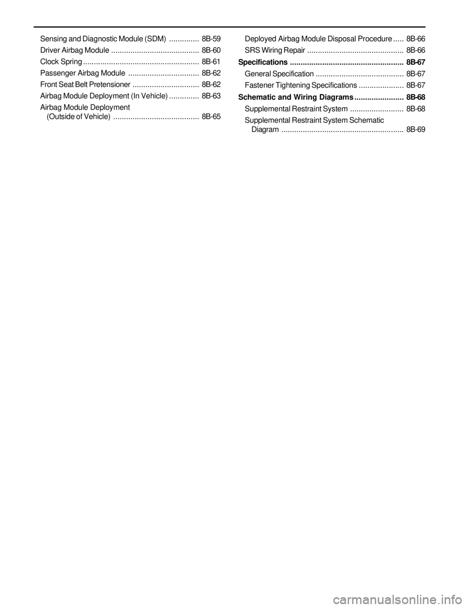
Sensing and Diagnostic Module (SDM)..............8B-59
Driver Airbag Module .........................................8B-60
Clock Spring......................................................8B-61
Passenger Airbag Module.................................8B-62
Front Seat Belt Pretensioner...............................8B-62
Airbag Module Deployment (In Vehicle)..............8B-63
Airbag Module Deployment
(Outside of Vehicle)........................................8B-65Deployed Airbag Module Disposal Procedure.....8B-66
SRS Wiring Repair.............................................8B-66
Specifications.....................................................8B-67
General Specification .........................................8B-67
Fastener Tightening Specifications.....................8B-67
Schematic and Wiring Diagrams.......................8B-68
Supplemental Restraint System.........................8B-68
Supplemental Restraint System Schematic
Diagram.........................................................8B-69