1997 SSANGYONG KORANDO rear door lock
[x] Cancel search: rear door lockPage 1843 of 2053
SECTION 9S
BODY REAR END
CAUTION: Disconnect the negative battery cable before removing or installing any electrical unit or when a
tool or equipment could easily come in contact with exposed electrical terminals. Disconnecting this cable
will help prevent personal injury and damage to the vehicle. The ignition must also be in LOCK unless
otherwise noted.
TABLE OF CONTENTS
Description and Operation...................................9S-2
Fuel Filler Door.....................................................9S-2
Components Locator............................................9S-3
Lighting System..................................................9S-3
Repair Instructions................................................9S-4On-Vehicle Service Unit Repair................................9S-4
Fuel Filler Door.....................................................9S-4
Fuel Filler Door Remote Handle and Cable............9S-4
Specifications.......................................................9S-5
Fastener Tightening Specifications.......................9S-5
Page 1849 of 2053
SSANGYONG MY2002
9T1-2 REMOTE KEYLESS ENTRY AND ANTI-THEFT SYSTEM
DESCRIPTION AND OPERATION
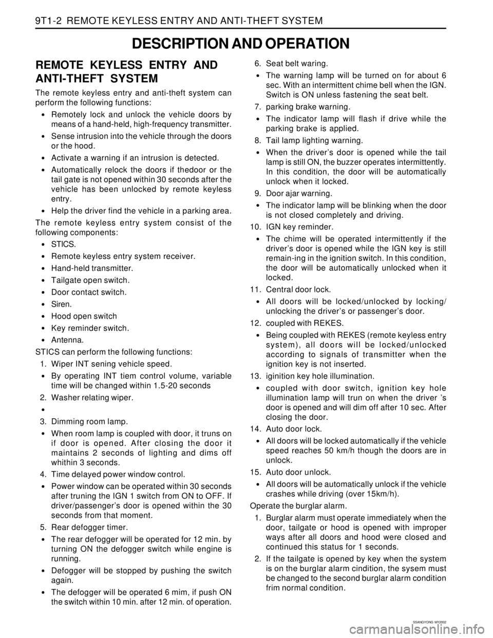
REMOTE KEYLESS ENTRY AND
ANTI-THEFT SYSTEM
The remote keyless entry and anti-theft system can
perform the following functions:
•Remotely lock and unlock the vehicle doors by
means of a hand-held, high-frequency transmitter.
Sense intrusion into the vehicle through the doors
or the hood.
Activate a warning if an intrusion is detected.
Automatically relock the doors if thedoor or the
tail gate is not opened within 30 seconds after the
vehicle has been unlocked by remote keyless
entry.
Help the driver find the vehicle in a parking area.
The remote keyless entry system consist of the
following components:
STICS.
Remote keyless entry system receiver.
Hand-held transmitter.
Tailgate open switch.
Door contact switch.
Siren.
Hood open switch
Key reminder switch.
Antenna.
STICS can perform the following functions:
1. Wiper INT sening vehicle speed.
By operating INT tiem control volume, variable
time will be changed within 1.5-20 seconds
2. Washer relating wiper.
3. Dimming room lamp.
When room lamp is coupled with door, it truns on
if door is opened. After closing the door it
maintains 2 seconds of lighting and dims off
whithin 3 seconds.
4. Time delayed power window control.
Power window can be operated within 30 seconds
after truning the IGN 1 switch from ON to OFF. If
driver/passenger’s door is opened within the 30
seconds from that moment.
5. Rear defogger timer.
The rear defogger will be operated for 12 min. by
turning ON the defogger switch while engine is
running.
Defogger will be stopped by pushing the switch
again.
The defogger will be operated 6 mim, if push ON
the switch within 10 min. after 12 min. of operation.6. Seat belt waring.
The warning lamp will be turned on for about 6
sec. With an intermittent chime bell when the IGN.
Switch is ON unless fastening the seat belt.
7. parking brake warning.
The indicator lamp will flash if drive while the
parking brake is applied.
8. Tail lamp lighting warning.
When the driver’s door is opened while the tail
lamp is still ON, the buzzer operates intermittently.
In this condition, the door will be automatically
unlock when it locked.
9. Door ajar warning.
The indicator lamp will be blinking when the door
is not closed completely and driving.
10. IGN key reminder.
The chime will be operated intermittently if the
driver’s door is opened while the IGN key is still
remain-ing in the ignition switch. In this condition,
the door will be automatically unlocked when it
locked.
11. Central door lock.
All doors will be locked/unlocked by locking/
unlocking the driver’s or passenger’s door.
12. coupled with REKES.
Being coupled with REKES (remote keyless entry
system), all doors will be locked/unlocked
according to signals of transmitter when the
ignition key is not inserted.
13. iginition key hole illumination.
coupled with door switch, ignition key hole
illumination lamp will trun on when the driver ’s
door is opened and will dim off after 10 sec. After
closing the door.
14. Auto door lock.
All doors will be locked automatically if the vehicle
speed reaches 50 km/h though the doors are in
unlock.
15. Auto door unlock.
All doors will be automatically unlock if the vehicle
crashes while driving (over 15km/h).
Operate the burglar alarm.
1. Burglar alarm must operate immediately when the
door, tailgate or hood is opened with improper
ways after all doors and hood were closed and
continued this status for 1 seconds.
2. If the tailgate is opened by key when the system
is on the burglar alarm cindition, the sysem must
be changed to the second burglar alarm condition
frim normal condition.
Page 1851 of 2053
SSANGYONG MY2002
9T1-4 REMOTE KEYLESS ENTRY AND ANTI-THEFT SYSTEM
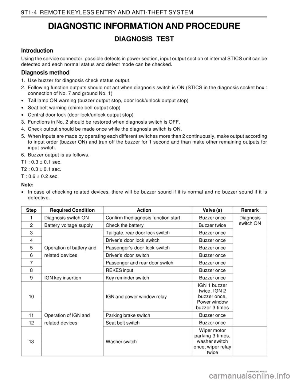
DIAGNOSTIC INFORMATION AND PROCEDURE
DIAGNOSIS TEST
Introduction
Using the service connector, possible defects in power section, input output section of internal STICS unit can be
detected and each normal status and defect mode can be checked.
Diagnosis method
1. Use buzzer for diagnosis check status output.
2. Following function outputs should not act when diagnosis switch is ON (STICS in the diagnosis socket box :
connection of No. 7 and ground No. 1)
Tail lamp ON warning (buzzer output stop, door lock/unlock output stop)
Seat belt warning (chime bell output stop)
Central door lock (door lock/unlock output stop)
3. Functions in No. 2 should be restored when diagnosis switch is OFF.
4. Check output should be made once while the diagnosis switch is ON.
5. When inputs are made by operating each different switches more than 2 continuously, make output according
to input order (buzzer ON) and trun off the buzzer for 1 second and than make other remaining outputs for
input switch.
6. Buzzer output is as follows.
T1 : 0.3 ± 0.1 sec.
T2 : 0.3 ± 0.1 sec.
T : 0.6 ± 0.2 sec.
Note:
In case of checking related devices, there will be buzzer sound if it is normal and no buzzer sound if it is
defective.
Step Required ConditionActionRemark Valve (s)
Diagnosis switch ON
Battery voltage supply
Operation of battery and
related devices
IGN key insertion
Operation of IGN and
related devicesBuzzer once
Buzzer twice
Buzzer once
Buzzer once
Buzzer once
Buzzer once
Buzzer once
Buzzer once
Buzzer once
IGN 1 buzzer
twice, IGN 2
buzzer once,
Power window
buzzer 3 times
Buzzer once
Buzzer once
Wiper motor
parking 3 times,
washer switch
once, wiper relay
twice Confirm thediagnosis function start
Check the battery
Tailgate, rear door lock switch
Driver’s door lock switch
Passenger’s door lock switch
Driver’s door switch
Passenger and rear door switch
REKES input
Key reminder switch
IGN and power window relay
Parking brake switch
Seat belt switch
Washer switch1
2
3
4
5
6
7
8
9
10
11
12
13Diagnosis
switch ON
Page 1868 of 2053
2-4 2-4 2-4 2-4
2-4
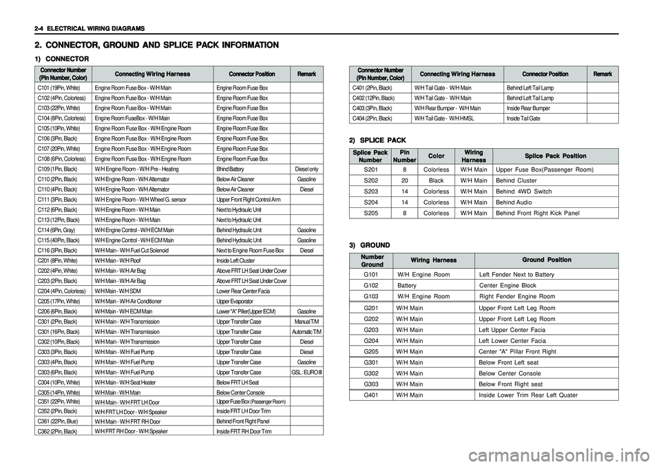
ELECTRICAL WIRING DIAGRAMS ELECTRICAL WIRING DIAGRAMSELECTRICAL WIRING DIAGRAMS ELECTRICAL WIRING DIAGRAMS
ELECTRICAL WIRING DIAGRAMS
Engine Room Fuse Box - W/H Main
Engine Room Fuse Box - W/H Main
Engine Room Fuse Box - W/H Main
Engine Room FuseBox - W/H Main
Engine Room Fuse Box - W/H Engine Room
Engine Room Fuse Box - W/H Engine Room
Engine Room Fuse Box - W/H Engine Room
Engine Room Fuse Box - W/H Engine Room
W/H Engine Room - W/H Pre - Heating
W/H Engine Room - W/H Alternator
W/H Engine Room - W/H Alternator
W/H Engine Room - W/H Wheel G. sensor
W/H Engine Room - W/H Main
W/H Engine Room - W/H Main
W/H Engine Control - W/H ECM Main
W/H Engine Control - W/H ECM Main
W/H Main - W/H Fuel Cut Solenoid
W/H Main - W/H Roof
W/H Main - W/H Air Bag
W/H Main - W/H Air Bag
W/H Main - W/H SDM
W/H Main - W/H Air Conditioner
W/H Main - W/H ECM Main
W/H Main - W/H Transmission
W/H Main - W/H Transmission
W/H Main - W/H Transmission
W/H Main - W/H Fuel Pump
W/H Main - W/H Fuel Pump
W/H Main - W/H Fuel Pump
W/H Main - W/H Seat Heater
W/H Main - W/H Main
W/H Main - W/H FRT LH Door
W/H FRT LH Door - W/H Speaker
W/H Main - W/H FRT RH Door
W/H FRT RH Door - W/H Speaker
G201W/H Main Upper Front Left Leg Room
G202W/H Main Upper Front Left Leg Room
G203W/H Main Left Upper Center Facia
G204W/H Main Left Lower Center Facia
G205W/H Main Center "A" Pillar Front Right
G301W/H Main Below Front Left seat
G302W/H Main Below Center Console
G303W/H Main Below Front Right seat
G401W/H Main Inside Lower Trim Rear Left Quater
Engine Room Fuse Box
Engine Room Fuse Box
Engine Room Fuse Box
Engine Room Fuse Box
Engine Room Fuse Box
Engine Room Fuse Box
Engine Room Fuse Box
Engine Room Fuse Box
Bhind Battery
Below Air Cleaner
Below Air Cleaner
Upper Front Right Control Arm
Next to Hydraulic Unit
Next to Hydraulic Unit
Behind Hydraulic Unit
Behind Hydraulic Unit
Next to Engine Room Fuse Box
Inside Left Cluster
Above FRT LH Seat Under Cover
Above FRT LH Seat Under Cover
Lower Rear Center Facia
Upper Evaporator
Lower "A" Piller(Upper ECM)
Upper Transfer Case
Upper Transfer Case
Upper Transfer Case
Upper Transfer Case
Upper Transfer Case
Upper Transfer Case
Below FRT LH Seat
Below Center Console
Upper Fuse Box
(Passenger Room)
Inside FRT LH Door Trim
Behind Front Right Panel
Inside FRT RH Door Trim
2. 2.2. 2.
2.
CONNECT CONNECTCONNECT CONNECT
CONNECT
OR, OR,OR, OR,
OR,
GR GR GR GR
GR
OUND AND SPLICE PA OUND AND SPLICE PAOUND AND SPLICE PA OUND AND SPLICE PA
OUND AND SPLICE PA
CK INFORMA CK INFORMACK INFORMA CK INFORMA
CK INFORMA
TION TIONTION TION
TION1) 1)1) 1)
1)
CONNECTOR CONNECTORCONNECTOR CONNECTOR
CONNECTORConnector Number Connector NumberConnector Number Connector Number
Connector Number
(Pin Number, Color) (Pin Number, Color)(Pin Number, Color) (Pin Number, Color)
(Pin Number, Color)Connecting Connecting Connecting Connecting
Connecting
Wiring Harness Wiring HarnessWiring Harness Wiring Harness
Wiring Harness
Connector Position Connector PositionConnector Position Connector Position
Connector Position
C101 (19Pin, White)
C102 (4Pin, Colorless)
C103 (22Pin, White)
C104 (8Pin, Colorless)
C105 (10Pin, White)
C106 (3Pin, Black)
C107 (20Pin, White)
C108 (6Pin, Colorless)
C109 (1Pin, Black)
C110 (2Pin, Black)
C110 (4Pin, Black)
C111 (3Pin, Black)
C112 (6Pin, Black)
C113 (12Pin, Black)
C114 (6Pin, Gray)
C115 (40Pin, Black)
C116 (3Pin, Black)
C201 (8Pin, White)
C202 (4Pin, White)
C203 (2Pin, Black)
C204 (4Pin, Colorless)
C205 (17Pin, White)
C206 (6Pin, Black)
C301 (2Pin, Black)
C301 (16Pin, Black)
C302 (10Pin, Black)
C303 (3Pin, Black)
C303 (4Pin, Black)
C303 (6Pin, Black)
C304 (10Pin, White)
C305 (14Pin, White)
C351 (22Pin, White)
C352 (2Pin, Black)
C361 (22Pin, Blue)
C362 (2Pin, Black)
2) 2)2) 2)
2)
SPLICE PACK SPLICE PACKSPLICE PACK SPLICE PACK
SPLICE PACK
S201
S202
S203
S204
S205Splice Pack Position Splice Pack PositionSplice Pack Position Splice Pack Position
Splice Pack Position Wiring WiringWiring Wiring
Wiring
Harness HarnessHarness Harness
Harness Color ColorColor Color
Color Splice Pack Splice PackSplice Pack Splice Pack
Splice Pack
Number NumberNumber Number
Number
Colorless
Black
Colorless
Colorless
ColorlessW/H Main
W/H Main
W/H Main
W/H Main
W/H MainUpper Fuse Box(Passenger Room)
Behind Cluster
Behind 4WD Switch
Behind Audio
Behind Front Right Kick Panel
Remark RemarkRemark Remark
Remark
Diesel only
Gasoline
Diesel
Gasoline
Gasoline
Diesel
Gasoline
Manual T/M
Automatic T/M
Diesel
Diesel
Gasoline
GSL : EURO IIIBehind Left Tail Lamp
Behind Left Tail Lamp
Inside Rear Bumper
Inside Tail Gate
Connector Number Connector NumberConnector Number Connector Number
Connector Number
(Pin Number, Color) (Pin Number, Color)(Pin Number, Color) (Pin Number, Color)
(Pin Number, Color)Connecting Connecting Connecting Connecting
Connecting
Wiring Harness Wiring HarnessWiring Harness Wiring Harness
Wiring Harness
Connector Position Connector PositionConnector Position Connector Position
Connector Position
C401 (2Pin, Black)
C402 (12Pin, Black)
C403 (3Pin, Black)
C404 (2Pin, Black)W/H Tail Gate - W/H Main
W/H Tail Gate - W/H Main
W/H Rear Bumper - W/H Main
W/H Tail Gate - W/H HMSL
Remark RemarkRemark Remark
Remark
3) 3)3) 3)
3)
GROUND GROUNDGROUND GROUND
GROUND
G101
G102
G103Ground Position Ground PositionGround Position Ground Position
Ground Position
Wiring Harness Wiring HarnessWiring Harness Wiring Harness
Wiring Harness Number NumberNumber Number
Number
Ground GroundGround Ground
Ground
W/H Engine Room
Battery
W/H Engine RoomLeft Fender Next to Battery
Center Engine Block
Right Fender Engine Room
Pin PinPin Pin
Pin
Number NumberNumber Number
Number
8
20
14
14
8
Page 1871 of 2053
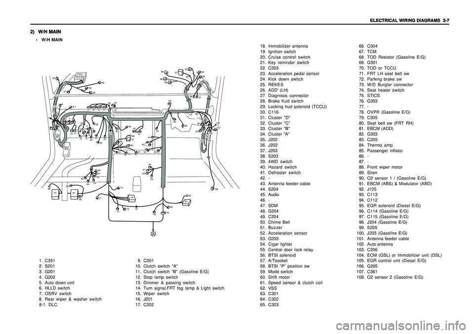
ELECTRICAL WIRING DIAGRAMS ELECTRICAL WIRING DIAGRAMSELECTRICAL WIRING DIAGRAMS ELECTRICAL WIRING DIAGRAMS
ELECTRICAL WIRING DIAGRAMS
2-7 2-7 2-7 2-7
2-7
2) 2)2) 2)
2)
W/H MAIN W/H MAINW/H MAIN W/H MAIN
W/H MAIN• W/H MAIN
1. C351
2. S201
3. G201
4. G202
5. Auto down unit
6. HLLD switch
7. OSRV switch
8. Rear wiper & washer switch
8-1. DLC9. C201
10. Clutch switch "A"
11. Clutch switch "B" (Gasoline E/G)
12. Stop lamp switch
13. Dimmer & passing switch
14. Turn signal,FRT fog lamp & Light switch
15. Wiper switch
16. J201
17. C20218. Immobilizer antenna
19. Ignition switch
20. Cruise control switch
21. Key reminder switch
22. C203
23. Acceleration pedal sensor
24. Kick down switch
25. REKES
26. ADD' (LH)
27. Diagnosis connector
28. Brake fluid switch
29. Locking hud solenoid (TCCU)
30. C116
31. Cluster "D"
32. Cluster "C"
33. Cluster "B"
34. Cluster "A"
35. J202
36. J202
37. J203
38. S203
39. 4WD switch
40. Hazard switch
41. Defroster switch
42. -
43. Antenna feeder cable
44. S204
45. Audio
46. -
47. SDM
48. G204
49. C204
50. Chime Bell
51. Buzzer
52. Acceleration sensor
53. G203
54. Cigar lighter
55. Central door lock relay
56. BTSI solenoid
57. A/Tsocket
58. BTSI "P" position sw
59. Mode switch
60. Shift motor
61. Speed sensor & clutch coil
62. VSS
63. C301
64. C302
65. C30366. C304
67. TCM
68. TOD Resistor (Gasoline E/G)
69. G301
70. TOD or TCCU
71. FRT LH seat belt sw
72. Parking brake sw
73. W/D Burglar connector
74. Seat heater switch
75. STICS
76. G303
77. -
78. OVPR (Gasoline E/G)
79. C305
80. Seat belt sw (FRT RH)
81. EBCM (ADD)
82. G303
83. C205
84. Thermo amp
85. Passenger inflator
86. -
87. -
88. Front wiper motor
89. Siren
90. O2 sensor 1 / (Gasoline E/G)
91. EBCM (ABS) & Modulator (ABD)
92. J105
93. C113
94. C112
95. EGR solenoid (Diesel E/G)
96. C114 (Gasoline E/G)
97. C115 (Gasoline E/G)
98. J204 (Gasoline E/G)
99. S205
100.J205 (Gasoline E/G)
101.Antenna feeder cable
102.Auto antenna
103.C206
104.ECM (GSL) or Immobilizer unit (DSL)
105.EGR control unit (Diesel E/G)
106. G205
107.C361
108. O2 sensor 2 (Gasoline E/G)
FUSE
BOX
RELAY
BOX
FUSE &
RELAY BOX
A
1011
12131415171618192021222829
30
26
27
31323334
35
3637
38
394041
43
83888990
91
93
9495
9296
979899102
101100
106107
104105
103
108
84
85
44
8-1
4748
49
50
51
52
53
45
55
54565758
60616263
6465
66
67
68
71
72
73
74
7576
78
7980
8182
69
70
59
232425
13
4259678
Page 1874 of 2053
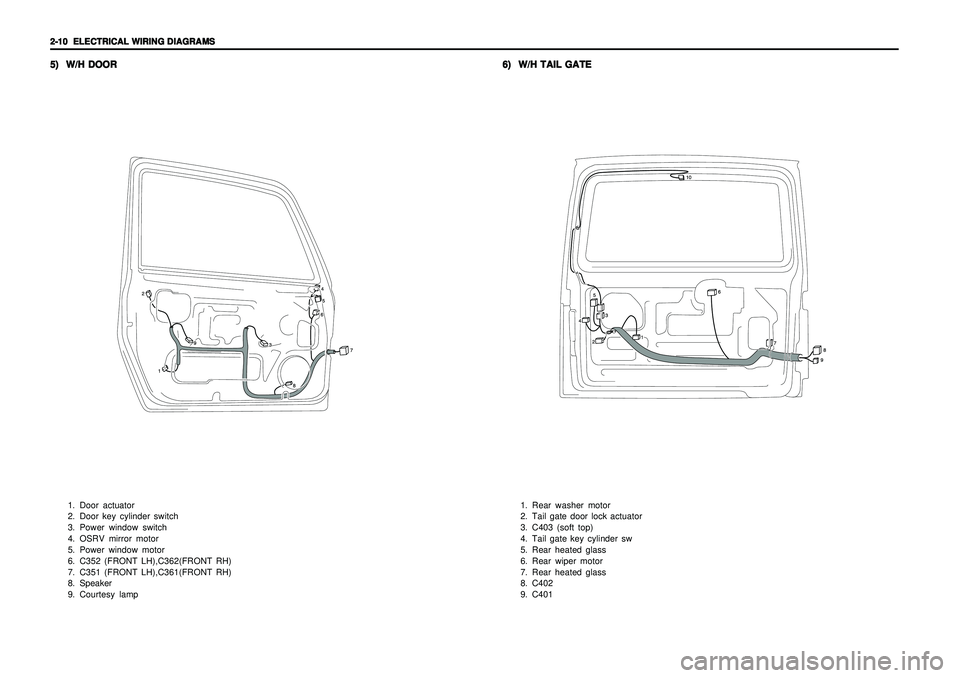
2-10 2-10 2-10 2-10
2-10
ELECTRICAL WIRING DIAGRAMS ELECTRICAL WIRING DIAGRAMSELECTRICAL WIRING DIAGRAMS ELECTRICAL WIRING DIAGRAMS
ELECTRICAL WIRING DIAGRAMS5) 5)5) 5)
5)
W/H DOOR W/H DOORW/H DOOR W/H DOOR
W/H DOOR
1. Door actuator
2. Door key cylinder switch
3. Power window switch
4. OSRV mirror motor
5. Power window motor
6. C352 (FRONT LH),C362(FRONT RH)
7. C351 (FRONT LH),C361(FRONT RH)
8. Speaker
9. Courtesy lamp
6) 6)6) 6)
6)
W/H TAIL GATE W/H TAIL GATEW/H TAIL GATE W/H TAIL GATE
W/H TAIL GATE
1. Rear washer motor
2. Tail gate door lock actuator
3. C403 (soft top)
4. Tail gate key cylinder sw
5. Rear heated glass
6. Rear wiper motor
7. Rear heated glass
8. C402
9. C401
Page 1893 of 2053
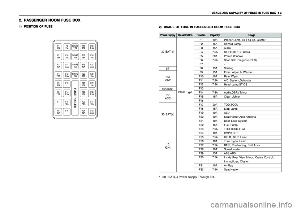
USAGE AND CAPACITY OF FUSES IN FUSE BOX USAGE AND CAPACITY OF FUSES IN FUSE BOX USAGE AND CAPACITY OF FUSES IN FUSE BOX USAGE AND CAPACITY OF FUSES IN FUSE BOX
USAGE AND CAPACITY OF FUSES IN FUSE BOX
4-3 4-34-3 4-3
4-3
2. 2.2. 2.
2.
PASSENGER ROOM FUSE BOX PASSENGER ROOM FUSE BOXPASSENGER ROOM FUSE BOX PASSENGER ROOM FUSE BOX
PASSENGER ROOM FUSE BOX1) 1)1) 1)
1)
POSITION OF FUSE POSITION OF FUSEPOSITION OF FUSE POSITION OF FUSE
POSITION OF FUSE
2) 2)2) 2)
2)
USAGE OF FUSE IN PASSENGER ROOM FUSE BOX USAGE OF FUSE IN PASSENGER ROOM FUSE BOXUSAGE OF FUSE IN PASSENGER ROOM FUSE BOX USAGE OF FUSE IN PASSENGER ROOM FUSE BOX
USAGE OF FUSE IN PASSENGER ROOM FUSE BOX
10A
15A
15A
7.5A
30A
7.5A
-
15A
15A
10A
7.5A
7.5A
-
7.5A
15A
20A
15A
10A
10A
10A
15A
7.5A
10A
7.5A
10A
7.5A
10A
15A
7.5A
10A
7.5A F1
F2
F3
F4
F5
F6
F7
F8
F9
F10
F11
F12
F13
F14
F15
F16
F17
F18
F19
F20
F21
F22
F23
F24
F25
F26
F27
F28
F29
F30
F31
F32
Power Supply Power SupplyPower Supply Power Supply
Power Supply
Classification ClassificationClassification Classification
Classification
Fuse No Fuse NoFuse No Fuse No
Fuse No
Capacity CapacityCapacity Capacity
Capacity
Usage UsageUsage Usage
Usage* 30 : BAT(+) Power Supply Through Ef1.
Blade TypeInterior Lamp, Rr Fog Lp, Cluster
Hazard Lamp
Audio
STICS,REKES,Clock
Power Window
Seat Belt, Diagnosis(DLC)
-
Starting
Front Wiper & Washer
Rear Wiper
A/C System,Defroster
Head Lamp,STICS
-
Audio,OSRV Mirror
Cigar Lighter
TOD,TCCU
Stop Lamp
ABD
Seat Heater,Auto Antenna
Door Lock System
Fuel Pump
TOD,TCCU,TCM
OVPR,EGR
HLLD, B/UP Lamp
Turn Signal Lamp
BTSI, Pre-heating, Shift Lock
Speedometer
ABS,ABD
Inside Rear View Mirror, Cruise Control,
Immobilizer, Cluster
Air Bag
Seat Heater
30 BAT(+)
ST
15A
IGN2
30 BAT(+)15C
ACC 15A IGN1
15
IGN1
Page 1898 of 2053
1) VSS(VEHICLE SPEED SENSOR), METER(SPEEDO, TACHO) & GAUGE(FUEL, TEMPERATURE)
- GASOLINE ........................................................................................................................................................... 5-96
(1) W/O EURO III .................................................................................................................................................................................... 5-96
(2) W/ EURO III ....................................................................................................................................................................................... 5-98
2) WARNING LAMP(ENGINE CHECK, AIR BAG, EBD, ABS), TCS INDICATOR............................................. 5-100
3) INDICATOR(DEFROSTER, WINTER MODE, POWR MODE, 4WD LOW, 4WD HIGH, 4WD CHECK)..... 5-102
4) WARNING LAMP (SEAT BELT, DOOR OPEN, PARKING BRAKE), INDICATOR (BATTERY CHARGING,
GLOW).................................................................................................................................................................. 5-104
5) FRONT FOG LAMP, TURN SIGNAL, HAZARD, HIGH BEAM ......................................................................... 5-106
6) DIGITAL CLOCK,WARNING (OIL PRESSURE, LOW FUEL LEVEL) CLUSTER ILLUMINATION............... 5-108
7) SELECTOR LEVER POSITION LAMP (P,R,N,D,3,2,1).................................................................................... 5-110
19. 19.19. 19.
19.
STICS(SUPER STICS(SUPER STICS(SUPER STICS(SUPER
STICS(SUPER
TIME & ALARM INTEGRA TIME & ALARM INTEGRATIME & ALARM INTEGRA TIME & ALARM INTEGRA
TIME & ALARM INTEGRA
TED CONTR TED CONTRTED CONTR TED CONTR
TED CONTR
OL SYSTEM) OL SYSTEM)OL SYSTEM) OL SYSTEM)
OL SYSTEM)
................................ ................................................................ ................................
................................
5-112 5-112 5-112 5-112
5-112
1) STICS UNIT .......................................................................................................................................................... 5-112
2) FRONT WIPER CIRCUIT.................................................................................................................................... 5-114
3) CENTRAL DOOR LOCK SYSTEM ..................................................................................................................... 5-116
4) KEYLESS, KEY REMINDER SWITCH, SIREN, CHIME BELL BUZZER ........................................................ 5-118
5) DEFROSTER........................................................................................................................................................ 5-120
6) LAMP(ROOM, DOOR COURTESY LH/RH, LUGGAGE), DOOR CONTACT SWITCH .................................. 5-122
20. 20.20. 20.
20.
SEA SEASEA SEA
SEA
T HEA T HEAT HEA T HEA
T HEA
TER TERTER TER
TER
.......................................................................................................................... .................................................................................................................................................................................................................................................... ..........................................................................................................................
..........................................................................................................................
5-124 5-124 5-124 5-124
5-124
21. 21.21. 21.
21.
ST STST ST
ST
OP LAMP OP LAMPOP LAMP OP LAMP
OP LAMP
, ,, ,
,
BTSI (BRAKE BTSI (BRAKE BTSI (BRAKE BTSI (BRAKE
BTSI (BRAKE
TRANSMISSION SHIFT INTERLOCK) TRANSMISSION SHIFT INTERLOCK)TRANSMISSION SHIFT INTERLOCK) TRANSMISSION SHIFT INTERLOCK)
TRANSMISSION SHIFT INTERLOCK)
................................... ...................................................................... ...................................
...................................
5-126 5-126 5-126 5-126
5-126
1) METAL TOP .......................................................................................................................................................... 5-126
2) SOFT TOP............................................................................................................................................................ 5-128
22. 22.22. 22.
22.
POWER WINDOW POWER WINDOWPOWER WINDOW POWER WINDOW
POWER WINDOW
..................................................................................................................... .......................................................................................................................................................................................................................................... .....................................................................................................................
.....................................................................................................................
5-130 5-130 5-130 5-130
5-130
23. 23.23. 23.
23.
ELECTRIC OSRV (OUTSIDE REAR VIEW) MIRROR ELECTRIC OSRV (OUTSIDE REAR VIEW) MIRRORELECTRIC OSRV (OUTSIDE REAR VIEW) MIRROR ELECTRIC OSRV (OUTSIDE REAR VIEW) MIRROR
ELECTRIC OSRV (OUTSIDE REAR VIEW) MIRROR
........................................................... ...................................................................................................................... ...........................................................
...........................................................
5-132 5-132 5-132 5-132
5-132
24. 24.24. 24.
24.
REAR REAR REAR REAR
REAR
WIPER & WIPER & WIPER & WIPER &
WIPER &
W WW W
W
ASHER ASHERASHER ASHER
ASHER
...................................................................................................... ............................................................................................................................................................................................................ ......................................................................................................
......................................................................................................
5-134 5-134 5-134 5-134
5-134
25. 25.25. 25.
25.
CIGARETTE LIGHTER, HORN CIGARETTE LIGHTER, HORNCIGARETTE LIGHTER, HORN CIGARETTE LIGHTER, HORN
CIGARETTE LIGHTER, HORN
................................................................................................ ................................................................................................................................................................................................ ................................................................................................
................................................................................................
5-136 5-136 5-136 5-136
5-136
26.HEAD LAMP 26.HEAD LAMP26.HEAD LAMP 26.HEAD LAMP
26.HEAD LAMP
.............................................................................................................................. ............................................................................................................................................................................................................................................................ ..............................................................................................................................
..............................................................................................................................
5-138 5-138 5-138 5-138
5-138
27. 27.27. 27.
27.
HEAD LAMP LEVELING DEVICE (HLLD) HEAD LAMP LEVELING DEVICE (HLLD)HEAD LAMP LEVELING DEVICE (HLLD) HEAD LAMP LEVELING DEVICE (HLLD)
HEAD LAMP LEVELING DEVICE (HLLD)
.............................................................................. ............................................................................................................................................................ ..............................................................................
..............................................................................
5-140 5-140 5-140 5-140
5-140