1997 SSANGYONG KORANDO lock
[x] Cancel search: lockPage 1067 of 2053
SSANGYONG MY2002
4F-84 ABS AND TCS
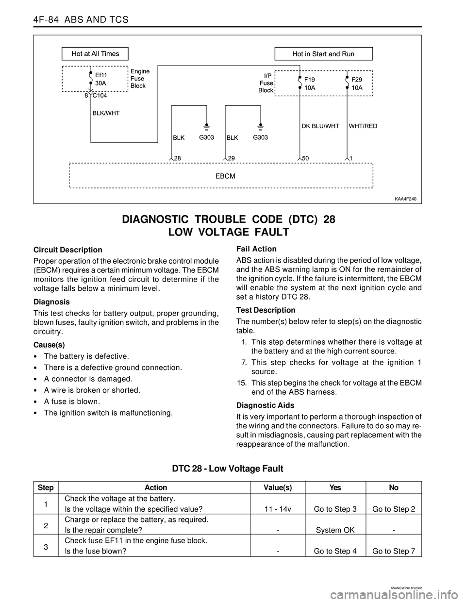
DIAGNOSTIC TROUBLE CODE (DTC) 28
LOW VOLTAGE FAULT
KAA4F240
Circuit Description
Proper operation of the electronic brake control module
(EBCM) requires a certain minimum voltage. The EBCM
monitors the ignition feed circuit to determine if the
voltage falls below a minimum level.
Diagnosis
This test checks for battery output, proper grounding,
blown fuses, faulty ignition switch, and problems in the
circuitry.
Cause(s)
The battery is defective.
There is a defective ground connection.
A connector is damaged.
A wire is broken or shorted.
A fuse is blown.
The ignition switch is malfunctioning.Fail Action
ABS action is disabled during the period of low voltage,
and the ABS warning lamp is ON for the remainder of
the ignition cycle. If the failure is intermittent, the EBCM
will enable the system at the next ignition cycle and
set a history DTC 28.
Test Description
The number(s) below refer to step(s) on the diagnostic
table.
1. This step determines whether there is voltage at
the battery and at the high current source.
7. This step checks for voltage at the ignition 1
source.
15. This step begins the check for voltage at the EBCM
end of the ABS harness.
Diagnostic Aids
It is very important to perform a thorough inspection of
the wiring and the connectors. Failure to do so may re-
sult in misdiagnosis, causing part replacement with the
reappearance of the malfunction.
Step
1
2
3
Action
Go to Step 3
System OK
Go to Step 4Go to Step 2
-
Go to Step 7 11 - 14v
-
-
Check the voltage at the battery.
Is the voltage within the specified value?
Charge or replace the battery, as required.
Is the repair complete?
Check fuse EF11 in the engine fuse block.
Is the fuse blown?
DTC 28 - Low Voltage Fault
Value(s) Yes No
Page 1068 of 2053
ABS AND TCS 4F-85
SSANGYONG MY2002
Step
4
5
6
7
8
9
10
11
12
13
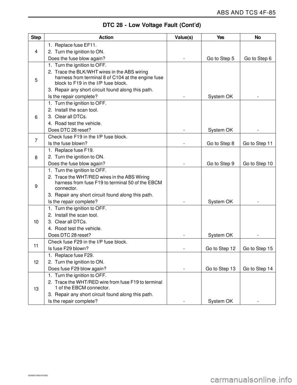
DTC 28 - Low Voltage Fault (Cont’d)
Action
Go to Step 5
System OK
System OK
Go to Step 8
Go to Step 9
System OK
System OK
Go to Step 12
Go to Step 13
System OKGo to Step 6
-
-
Go to Step 11
Go to Step 10
-
-
Go to Step 15
Go to Step 14
- -
-
-
-
-
-
-
-
-
-
1. Replace fuse EF11.
2. Turn the ignition to ON.
Does the fuse blow again?
1. Turn the ignition to OFF.
2. Trace the BLK/WHT wires in the ABS wiring
harness from terminal 8 of C104 at the engine fuse
block to F19 in the I/P fuse block.
3. Repair any short circuit found along this path.
Is the repair complete?
1. Turn the ignition to OFF.
2. Install the scan tool.
3. Clear all DTCs.
4. Road test the vehicle.
Does DTC 28 reset?
Check fuse F19 in the I/P fuse block.
Is the fuse blown?
1. Replace fuse F19.
2. Turn the ignition to ON.
Does the fuse blow again?
1. Turn the ignition to OFF.
2. Trace the WHT/RED wires in the ABS Wiring
harness from fuse F19 to terminal 50 of the EBCM
connector.
3. Repair any short circuit found along this path.
Is the repair complete?
1. Turn the ignition to OFF.
2. Install the scan tool.
3. Clear all DTCs.
4. Rood test the vehicle.
Does DTC 28 reset?
Check fuse F29 in the I/P fuse block.
Is fuse F29 blown?
1. Replace fuse F29.
2. Turn the ignition to ON.
Does fuse F29 blow again?
1. Turn the ignition to OFF.
2. Trace the WHT/RED wire from fuse F19 to terminal
1 of the EBCM connector.
3. Repair any short circuit found along this path.
Is the repair complete?
Value(s) Yes No
Page 1069 of 2053
SSANGYONG MY2002
4F-86 ABS AND TCS
Step
14
15
16
17
18
19
20
21
22
23
24
25
26
27
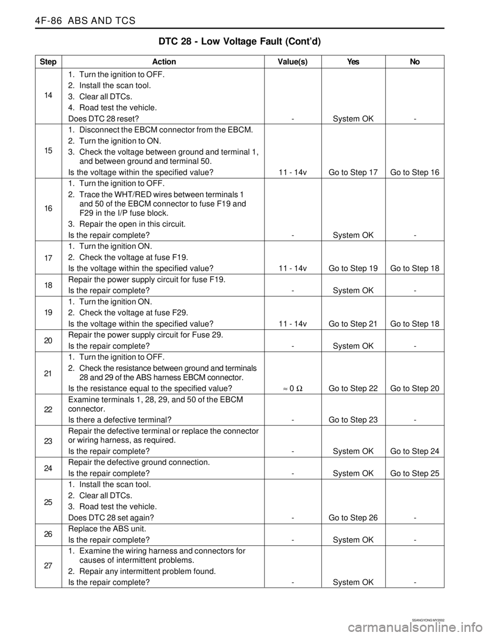
DTC 28 - Low Voltage Fault (Cont’d)
Action
System OK
Go to Step 17
System OK
Go to Step 19
System OK
Go to Step 21
System OK
Go to Step 22
Go to Step 23
System OK
System OK
Go to Step 26
System OK
System OK-
Go to Step 16
-
Go to Step 18
-
Go to Step 18
-
Go to Step 20
-
Go to Step 24
Go to Step 25
-
-
- -
11 - 14v
-
11 - 14v
-
11 - 14v
-
≈ 0 Ω
-
-
-
-
-
-
1. Turn the ignition to OFF.
2. Install the scan tool.
3. Clear all DTCs.
4. Road test the vehicle.
Does DTC 28 reset?
1. Disconnect the EBCM connector from the EBCM.
2. Turn the ignition to ON.
3. Check the voltage between ground and terminal 1,
and between ground and terminal 50.
Is the voltage within the specified value?
1. Turn the ignition to OFF.
2. Trace the WHT/RED wires between terminals 1
and 50 of the EBCM connector to fuse F19 and
F29 in the I/P fuse block.
3. Repair the open in this circuit.
Is the repair complete?
1. Turn the ignition ON.
2. Check the voltage at fuse F19.
Is the voltage within the specified value?
Repair the power supply circuit for fuse F19.
Is the repair complete?
1. Turn the ignition ON.
2. Check the voltage at fuse F29.
Is the voltage within the specified value?
Repair the power supply circuit for Fuse 29.
Is the repair complete?
1. Turn the ignition to OFF.
2. Check the resistance between ground and terminals
28 and 29 of the ABS harness EBCM connector.
Is the resistance equal to the specified value?
Examine terminals 1, 28, 29, and 50 of the EBCM
connector.
Is there a defective terminal?
Repair the defective terminal or replace the connector
or wiring harness, as required.
Is the repair complete?
Repair the defective ground connection.
Is the repair complete?
1. Install the scan tool.
2. Clear all DTCs.
3. Road test the vehicle.
Does DTC 28 set again?
Replace the ABS unit.
Is the repair complete?
1. Examine the wiring harness and connectors for
causes of intermittent problems.
2. Repair any intermittent problem found.
Is the repair complete?
Value(s) Yes No
Page 1076 of 2053
ABS AND TCS 4F-93
SSANGYONG MY2002
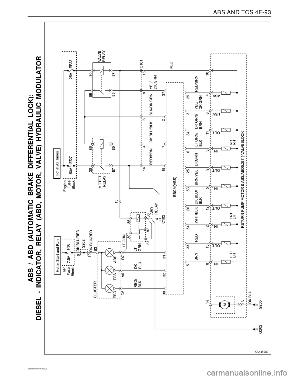
ABS / ABD (AUTOMATIC BRAKE DIFFERENTIAL LOCK):
DIESEL - INDICATOR, RELAY (ABD, MOTOR, VALVE) HYDRAULIC MODULATOR
KAA4F280
Page 1077 of 2053
SSANGYONG MY2002
4F-94 ABS AND TCS
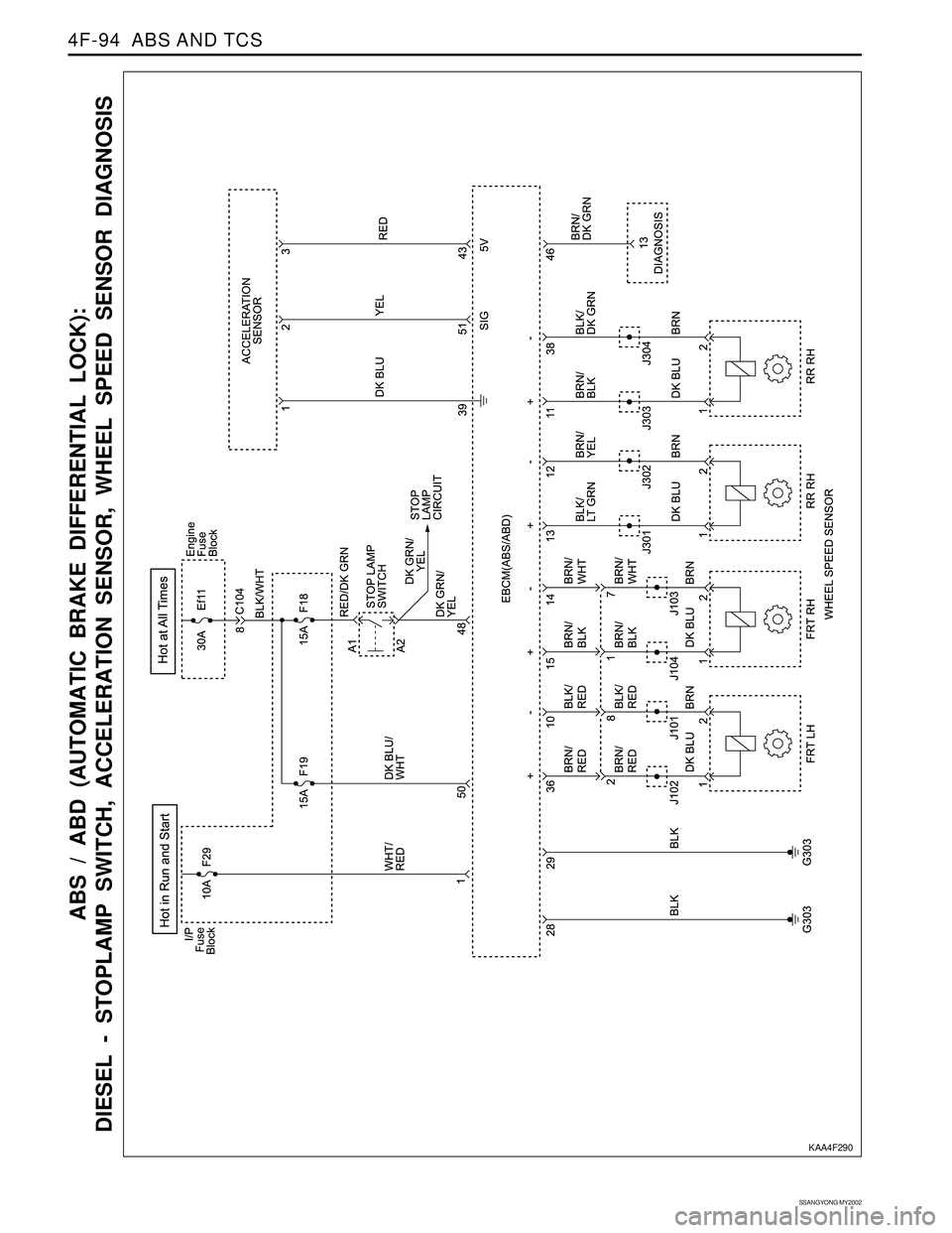
ABS / ABD (AUTOMATIC BRAKE DIFFERENTIAL LOCK):
DIESEL - STOPLAMP SWITCH, ACCELERATION SENSOR, WHEEL SPEED SENSOR DIAGNOSIS
KAA4F290
Page 1082 of 2053
ABS AND TCS 4F-99
SSANGYONG MY2002
REPAIR INSTRUCTIONS
ON-VEHICLE SERVICE
SERVICE PRECAUTIONS
Caution: Brake Fluid may irritate eyes and skin. In
case of contact, take the following actions:
Eye contact - rinse thoroughly with water.
Skin contact - wash with soap and water.
Ingestion - consult a physician immediately.
Caution: To help avoid personal injury due to poor
braking. DO NOT Tap into the vehicle’s brake system
to operate a trailer brake system.
Notice: When fasteners are removed, always reinstall
them at the same location from which they were
removed. If a fastener needs to be replaced, use the
correct part number fastener for is not available, a
fastener of equal size and strength (or stronger) may
be used. Fasteners that are not reused, and those
requiring thread-locking compound will be called out.
The correct torque values must be used when installing
fasteners that require them. If the above procedures
are not followed, parts or system damage could result.
Notice: Use only DOT-3 equivalent hydraulic brake
fluid. The use of DOT-5 (silicone) brake fluid is not
recommended. Reduced brake performance or
durability may result.
Notice: Avoid spilling brake fluid on any the vehicle’s
painted surfaces, wiring, cables or electrical
connectors. Brake fluid will damage paint and electrical
connections. If any fluid is spilled on the vehicle, flush
the area with water to lessen the damage.
Electronic System Service Precautions
Take care to avoid electronic brake control module
(EBCM) circuit overloading. In testing for opens or
shorts, do not ground or apply voltage to any circuit
unless instructed to do so by the diagnostic procedure.
Test circuits only with a high-impedance multi-meter.
Never remove or apply power to any control module
with the ignition switch in the ON position. Always turn
the ignition to the OFF position before removing or
connecting battery cables, fuses or connectors.
General Service Precautions
Disconnect the EBCM connector before performing any
vehicle welding work using an electric arc welder.
Do not attempt to disassemble any component
designated as nonserviceable. The hydraulic modulator
and the EBCM can be separated from each other and
replaced separately but cannot be serviced. They have
no replaceable parts, and there is no replaceable parts,
and there is no access to the components they contain.
Bleeding System
Replacement modulators are shipped already filled
and bled. In normal procedures requiring removal of
the modulator, such as to replace the EBCM, air will
not enter the modulator, and normal bleeding will be
all that is needed.
If air enters the hydraulic modulator, or if an unfilled
modulator is installed, use the brake bleeding program
in the scan tool to bleed the modulator. Manual
bleeding of the hydraulic modulator is not possible.
Page 1085 of 2053
SSANGYONG MY2002
4F-102 ABS AND TCS
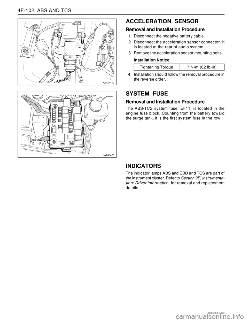
ACCELERATION SENSOR
Removal and Installation Procedure
1. Disconnect the negative battery cable.
2. Disconnect the acceleration sensor connector. It
is located at the rear of audio system.
3. Remove the acceleration sensor mounting bolts.
Installation Notice
SYSTEM FUSE
Removal and Installation Procedure
The ABS/TCS system fuse, EF11, is located in the
engine fuse block. Counting from the battery toward
the surge tank, it is the first system fuse in the row.
KAA4F410
KAA4F420
Tightening Torque 7 Nm (62 lb-in)
4. Installation should follow the removal procedure in
the reverse order.
INDICATORS
The indicator lamps ABS and EBD and TCS are part of
the instrument cluster. Refer to Section 9E, instrumenta-
tion/ Driver information, for removal and replacement
details.
Page 1095 of 2053
SECTION 5A
AUTOMATIC TRANSMISSION
CAUTION: Disconnect the negative battery cable before removing or installing any electrical unit or when a
tool or equipment could easily come in contact with exposed electrical terminals. Disconnecting this cable
will help prevent personal injury and damage to the vehicle. The ignition must also be in LOCK unless
otherwise noted.
TABLE OF CONTENTS
Description and Operation . . . . . . . . . . . . . . . . . 5A-2
BTRA M74 4WD Automatic Transmission . . . . . . 5A-2
Operators Interfaces . . . . . . . . . . . . . . . . . . . . . 5A-2
Control Systems . . . . . . . . . . . . . . . . . . . . . . . . 5A-3
Electronic Control System . . . . . . . . . . . . . . . . . 5A-3
Hydraulic Control System . . . . . . . . . . . . . . . . . . 5A-9
Hydraulic Control Circuit . . . . . . . . . . . . . . . . . . 5A-10
Power Train System . . . . . . . . . . . . . . . . . . . . . 5A-14
Power Flows . . . . . . . . . . . . . . . . . . . . . . . . . . 5A-18
Park and Neutral . . . . . . . . . . . . . . . . . . . . . . . 5A-20
Reverse . . . . . . . . . . . . . . . . . . . . . . . . . . . . . . 5A-22
Manual 1 . . . . . . . . . . . . . . . . . . . . . . . . . . . . . 5A-24
Drive 1 . . . . . . . . . . . . . . . . . . . . . . . . . . . . . . 5A-26
Drive 2 and Manual 2 . . . . . . . . . . . . . . . . . . . . 5A-28
Drive 3 and Manual 3 . . . . . . . . . . . . . . . . . . . . 5A-30
Drive 3 Lock Up and Manual 3 Lock Up . . . . . . 5A-32
Drive 4 (Overdrive) . . . . . . . . . . . . . . . . . . . . . 5A-34
Drive 4 Lock Up . . . . . . . . . . . . . . . . . . . . . . . . 5A-36
Diagnostic Information and Procedures . . . . . 5A-38
Diagnosis . . . . . . . . . . . . . . . . . . . . . . . . . . . . . 5A-38
Basic Knowledge Required . . . . . . . . . . . . . . . 5A-38
Functional Check Procedure . . . . . . . . . . . . . . . 5A-38
Transmission Fluid Level Service Procedure . . . 5A-38
Fluid Leak Diagnosis and Repair . . . . . . . . . . . 5A-39
Electrical / Garage Shift Test . . . . . . . . . . . . . . 5A-40
Road Test Procedure . . . . . . . . . . . . . . . . . . . . 5A-40
Electronic Adjustments . . . . . . . . . . . . . . . . . . 5A-40
Symptom Diagnosis . . . . . . . . . . . . . . . . . . . . . 5A-41
Drive Faults . . . . . . . . . . . . . . . . . . . . . . . . . . . 5A-41
Faulty Shift Pattern . . . . . . . . . . . . . . . . . . . . . . 5A-42Shift Quality Faults . . . . . . . . . . . . . . . . . . . . . . 5A-44
After Teardown Faults . . . . . . . . . . . . . . . . . . . 5A-46
Trouble Code Diagnosis - Gasoline Vehicle . . 5A-48
TCM Diagnostic System Overview . . . . . . . . . . 5A-48
Clearing Trouble Codes . . . . . . . . . . . . . . . . . . 5A-48
Diagnostic Trouble Codes . . . . . . . . . . . . . . . . 5A-48
Trouble Code Diagnosis - Diesel Vehicle . . . . . 5A-50
TCM Diagnostic System Overview . . . . . . . . . . 5A-50
Clearing Trouble Codes . . . . . . . . . . . . . . . . . . 5A-50
Diagnostic Trouble Codes . . . . . . . . . . . . . . . . 5A-50
Repair Instructions . . . . . . . . . . . . . . . . . . . . . . 5A-157
On-Vehicle Service . . . . . . . . . . . . . . . . . . . . . . . 5A-157
Transmission . . . . . . . . . . . . . . . . . . . . . . . . . . 5A-157
Unit Repair . . . . . . . . . . . . . . . . . . . . . . . . . . . . 5A-160
Rebuild Warnings . . . . . . . . . . . . . . . . . . . . . . 5A-160
Disassembly Procedure . . . . . . . . . . . . . . . . . . 5A-161
Assembly Procedure . . . . . . . . . . . . . . . . . . . . 5A-171
Front and Rear Band Adjustment . . . . . . . . . . . 5A-199
Gear Shift Control Lever . . . . . . . . . . . . . . . . . . 5A-202
Kickdown Switch . . . . . . . . . . . . . . . . . . . . . . . 5A-202
Specifications . . . . . . . . . . . . . . . . . . . . . . . . . . 5A-203
General Specification . . . . . . . . . . . . . . . . . . . . 5A-203
Fastener Tightening Specifications . . . . . . . . . . 5A-205
Schematic and Routing Diagrams . . . . . . . . . . 5A-206
TCM Wiring Diagrams (Gasoline Engine) . . . . . 5A-206
TCM Wiring Diagrams (Diesel Engine) . . . . . . . 5A-208
Connector End View . . . . . . . . . . . . . . . . . . . . . 5A-210
Special Tools and Equipment . . . . . . . . . . . . . 5A-211
Special Tools Table . . . . . . . . . . . . . . . . . . . . . 5A-211